EP0729895B1 - Resin cap - Google Patents
Resin cap Download PDFInfo
- Publication number
- EP0729895B1 EP0729895B1 EP96301387A EP96301387A EP0729895B1 EP 0729895 B1 EP0729895 B1 EP 0729895B1 EP 96301387 A EP96301387 A EP 96301387A EP 96301387 A EP96301387 A EP 96301387A EP 0729895 B1 EP0729895 B1 EP 0729895B1
- Authority
- EP
- European Patent Office
- Prior art keywords
- cap
- ring member
- skirt
- proper
- ring
- Prior art date
- Legal status (The legal status is an assumption and is not a legal conclusion. Google has not performed a legal analysis and makes no representation as to the accuracy of the status listed.)
- Expired - Lifetime
Links
- 229920005989 resin Polymers 0.000 title claims description 18
- 239000011347 resin Substances 0.000 title claims description 18
- 239000000463 material Substances 0.000 claims description 6
- 238000000465 moulding Methods 0.000 claims description 5
- 239000007924 injection Substances 0.000 claims description 2
- 230000004888 barrier function Effects 0.000 claims 1
- 238000002347 injection Methods 0.000 claims 1
- 238000007789 sealing Methods 0.000 description 15
- 239000007789 gas Substances 0.000 description 6
- 229920003023 plastic Polymers 0.000 description 6
- 239000004033 plastic Substances 0.000 description 6
- 238000000748 compression moulding Methods 0.000 description 4
- 238000001746 injection moulding Methods 0.000 description 4
- QVGXLLKOCUKJST-UHFFFAOYSA-N atomic oxygen Chemical compound [O] QVGXLLKOCUKJST-UHFFFAOYSA-N 0.000 description 3
- 230000015572 biosynthetic process Effects 0.000 description 3
- 238000007664 blowing Methods 0.000 description 3
- 238000010276 construction Methods 0.000 description 3
- 230000007246 mechanism Effects 0.000 description 3
- 239000001301 oxygen Substances 0.000 description 3
- 229910052760 oxygen Inorganic materials 0.000 description 3
- 230000003313 weakening effect Effects 0.000 description 3
- 229920001944 Plastisol Polymers 0.000 description 2
- PPBRXRYQALVLMV-UHFFFAOYSA-N Styrene Chemical compound C=CC1=CC=CC=C1 PPBRXRYQALVLMV-UHFFFAOYSA-N 0.000 description 2
- BZHJMEDXRYGGRV-UHFFFAOYSA-N Vinyl chloride Chemical compound ClC=C BZHJMEDXRYGGRV-UHFFFAOYSA-N 0.000 description 2
- 230000002411 adverse Effects 0.000 description 2
- 238000005452 bending Methods 0.000 description 2
- 235000014171 carbonated beverage Nutrition 0.000 description 2
- 239000011888 foil Substances 0.000 description 2
- 229920001684 low density polyethylene Polymers 0.000 description 2
- 239000004999 plastisol Substances 0.000 description 2
- 229920000728 polyester Polymers 0.000 description 2
- 230000002265 prevention Effects 0.000 description 2
- 238000010008 shearing Methods 0.000 description 2
- OEPOKWHJYJXUGD-UHFFFAOYSA-N 2-(3-phenylmethoxyphenyl)-1,3-thiazole-4-carbaldehyde Chemical compound O=CC1=CSC(C=2C=C(OCC=3C=CC=CC=3)C=CC=2)=N1 OEPOKWHJYJXUGD-UHFFFAOYSA-N 0.000 description 1
- 229920000178 Acrylic resin Polymers 0.000 description 1
- 239000004925 Acrylic resin Substances 0.000 description 1
- VGGSQFUCUMXWEO-UHFFFAOYSA-N Ethene Chemical compound C=C VGGSQFUCUMXWEO-UHFFFAOYSA-N 0.000 description 1
- 239000005977 Ethylene Substances 0.000 description 1
- 239000004677 Nylon Substances 0.000 description 1
- 239000004952 Polyamide Substances 0.000 description 1
- 239000004743 Polypropylene Substances 0.000 description 1
- 239000006096 absorbing agent Substances 0.000 description 1
- 229920000122 acrylonitrile butadiene styrene Polymers 0.000 description 1
- 229910052782 aluminium Inorganic materials 0.000 description 1
- XAGFODPZIPBFFR-UHFFFAOYSA-N aluminium Chemical compound [Al] XAGFODPZIPBFFR-UHFFFAOYSA-N 0.000 description 1
- 229920001577 copolymer Polymers 0.000 description 1
- 230000003247 decreasing effect Effects 0.000 description 1
- 229920001971 elastomer Polymers 0.000 description 1
- 230000008030 elimination Effects 0.000 description 1
- 238000003379 elimination reaction Methods 0.000 description 1
- 229920001038 ethylene copolymer Polymers 0.000 description 1
- 229920001903 high density polyethylene Polymers 0.000 description 1
- 229920000092 linear low density polyethylene Polymers 0.000 description 1
- 239000004707 linear low-density polyethylene Substances 0.000 description 1
- 239000004702 low-density polyethylene Substances 0.000 description 1
- 229920001179 medium density polyethylene Polymers 0.000 description 1
- 229910052751 metal Inorganic materials 0.000 description 1
- 239000002184 metal Substances 0.000 description 1
- 238000000034 method Methods 0.000 description 1
- 238000009740 moulding (composite fabrication) Methods 0.000 description 1
- 229920001778 nylon Polymers 0.000 description 1
- 229920002647 polyamide Polymers 0.000 description 1
- -1 polypropylene Polymers 0.000 description 1
- 229920001155 polypropylene Polymers 0.000 description 1
- 239000005060 rubber Substances 0.000 description 1
- 239000000243 solution Substances 0.000 description 1
- 229920003002 synthetic resin Polymers 0.000 description 1
- 239000000057 synthetic resin Substances 0.000 description 1
- 229920001169 thermoplastic Polymers 0.000 description 1
- 229920002725 thermoplastic elastomer Polymers 0.000 description 1
- 239000004416 thermosoftening plastic Substances 0.000 description 1
- 238000013022 venting Methods 0.000 description 1
Images


Classifications
-
- B—PERFORMING OPERATIONS; TRANSPORTING
- B65—CONVEYING; PACKING; STORING; HANDLING THIN OR FILAMENTARY MATERIAL
- B65D—CONTAINERS FOR STORAGE OR TRANSPORT OF ARTICLES OR MATERIALS, e.g. BAGS, BARRELS, BOTTLES, BOXES, CANS, CARTONS, CRATES, DRUMS, JARS, TANKS, HOPPERS, FORWARDING CONTAINERS; ACCESSORIES, CLOSURES, OR FITTINGS THEREFOR; PACKAGING ELEMENTS; PACKAGES
- B65D41/00—Caps, e.g. crown caps or crown seals, i.e. members having parts arranged for engagement with the external periphery of a neck or wall defining a pouring opening or discharge aperture; Protective cap-like covers for closure members, e.g. decorative covers of metal foil or paper
- B65D41/32—Caps or cap-like covers with lines of weakness, tearing-strips, tags, or like opening or removal devices, e.g. to facilitate formation of pouring openings
- B65D41/46—Snap-on caps or cap-like covers
- B65D41/48—Snap-on caps or cap-like covers non-metallic, e.g. made of paper or plastics
- B65D41/485—Snap-on caps or cap-like covers non-metallic, e.g. made of paper or plastics with integral internal sealing means
-
- B—PERFORMING OPERATIONS; TRANSPORTING
- B65—CONVEYING; PACKING; STORING; HANDLING THIN OR FILAMENTARY MATERIAL
- B65D—CONTAINERS FOR STORAGE OR TRANSPORT OF ARTICLES OR MATERIALS, e.g. BAGS, BARRELS, BOTTLES, BOXES, CANS, CARTONS, CRATES, DRUMS, JARS, TANKS, HOPPERS, FORWARDING CONTAINERS; ACCESSORIES, CLOSURES, OR FITTINGS THEREFOR; PACKAGING ELEMENTS; PACKAGES
- B65D41/00—Caps, e.g. crown caps or crown seals, i.e. members having parts arranged for engagement with the external periphery of a neck or wall defining a pouring opening or discharge aperture; Protective cap-like covers for closure members, e.g. decorative covers of metal foil or paper
- B65D41/32—Caps or cap-like covers with lines of weakness, tearing-strips, tags, or like opening or removal devices, e.g. to facilitate formation of pouring openings
Definitions
- the present invention relates to a resin cap having excellent sealing reliability and can openability, and more specifically, to a resin cap which can form reliable sealing and can be easily and exactly opened and has tamper-evident (TE) characteristics.
- TE tamper-evident
- a resin cap can be integrally molded, and has excellent moldability and flexibility, it can be fixed to a mouth portion of a container by a stopping operation and has been used heretofore in various forms.
- JP 51-10555 describes an unfair act-preventing closure composed of a synthetic resin having a handle on the outer surface of a skirt wall.
- the handle of this closure is spaced from an outer circumferential surface of the skirt wall and surrounding it. It is not a complete ring but arcuate and both its end portions are firmly fixed to the outer surface of the skirt wall.
- the inner surface of the handle is connected to the outer surface of the skirt wall by a plurality of easily breakable connecting pieces formed circumferentially at suitable distances.
- the prior art is significant because it provides a plastic cap which can be opened by hand without requiring any particular tool such as a cap opener and to which an unfair act-preventing function is imparted.
- a sealing reliability Circumferential protrusions are formed on the inner surface of the skirt wall, and when these protrusions are sealed with the neck portion of the container, the container is sealed.
- the skirt wall cannot easily be turned up, and the openability of the can becomes unsatisfactory. Since the protrusions for securing sealability are not formed over the entire circumference of the inner surface of the skirt wall, the closure of the above prior art has unsatisfactory sealing reliability.
- Another object of the invention is to provide a resin cap in which in a stopping action, a ring-like member protects a skirt portion of a cap proper, in a closure-closed condition, the ring member intimately contacts the outer surface of the skirt portion of the cap proper to maintain sealability, the ring-like member is removed at the time of opening the cap, the skirt portion can be easily removed from the mouth portion of the container, and in addition, the ring-like member has tamper-evident characteristics.
- a cap made from resin comprising:
- an opening tab is preferably formed in a part of the ring-like member.
- the skirt portion of the cap proper and the ring member are preferably formed by injection- or compression molding them integrally, thereafter making a cut by a cutter between the two to separate a portion excluding a bridge portion or further a connecting portion.
- the cap of the present invention is typically composed of a skirt portion in the cap proper and a ring member provided so as to cover the outer surface of the skirt portion, the skirt portion of the cap proper is provided with a plurality of slits extending in an axial direction at intervals in a circumferential direction, the skirt portion of the cap proper is separated from the ring member via a cutting face, the skirt portion and the ring member are integrally formed via a plurality of frangible bridges or further connecting portions on the upper side or under side of the cutting faces, and the outside surface of the skirt portion of the cap proper and the inner surface of the ring member are intimately contacting at a portion of the cutting faces.
- the skirt portion of the cap proper is provided with a plurality of slits extending in an axial direction at intervals in a circumferential direction whereby the skirt portion is broadened diametrically outwardly at the time of cap opening so that the cap proper can be easily removed from the mouth portion of the container.
- the skirt portion of the cap proper is separated from the ring member via a cutting face, but they are integrally molded through a plurality of frangible bridges or further connecting portions on the upper side or the lower side from the cutting face and the outer surface of the skirt portion of the cap proper and the inner surface of the ring member are contacted intimately at a portion of the cutting face.
- the skirt portion of the cap proper at least in the closed state is circumferentially bundled and fixed by the ring member so that the skirt portion is prevented from broadening outwardly and accurate sealability against the mouth portion of the container is maintained.
- This feature is especially important in the case of the cap of the present invention which is provided with axially extending slits in the skirt portion.
- the slits at the skirt portion act so as to weaken the engaging state between the mouth portion of the container and the protrusions of the skirt portion, but as a result of the action of circumferentially bundling and fixing by the ring member, the engaging state becomes firm and accurate.
- an opening tab is formed in a part of the ring member, divergence occurs between the ring member and the skirt portion at the cutting face by pushing up or down the tab whereby the bridge portion connecting the cap proper with the ring member is cut off by a shearing force. Because slits are formed in the skirt portion of the cap proper, when the ring member is removed from the skirt portion, the skirt portion is freely broadened diametrically outwardly. Thus, the cap proper is easily eliminated from the mouth portion of the container and can be opened easily without using a tool.
- the strength of the opening tab is reinforced, or its position can be clearly shown.
- the skirt portion of the cap proper and the ring member are typically formed by integral injection or compression molding, forming slits by a cutter between both to separate a portion excepting the bridge portions or further connecting portions, they can be produced by using a mold composed usually of a core and a cavity, and a molding procedure is easy.
- the frangible bridge portions may be formed, whereby the cap proper may be separated from the ring member in opening the cap.
- the cap proper may be separated from the ring member in opening the cap.
- tamper-evident characteristics become more marked.
- the lower end of the skirt portion is pushed up by a finger whereby by the existence of slits, the cap proper can be easily opened.
- connecting portions for connecting both may be positioned between the skirt portion of the cap proper and the ring member, and in opening the cap, the bridge portions are broken by pushing up or down the tab. Thereafter, by lifting the ring member, the engagement between the skirt portion of the cap proper and the mouth portion of the container can be released.
- the ring member can be utilized as an opening handle of the cap proper.
- An inner ring which is engaged with the inner circumferential side of the mouth portion of the container may be formed in the top panel portion.
- sealing may be performed at the inner circumferential side of the mouth portion of the container, and the sealing advantageously becomes more accurate.
- the lower end of the ring member may be positioned below the lower end of the skirt portion of the cap proper. By so doing, the lower end of the skirt portion of the cap proper is hidden by the ring member.
- the bridge portions necessary break. Therefore, tamper-evident characteristics can be increased.
- the lower end of the ring member and the lower end of the skirt portion of the cap proper may be provided so that they are positioned on the same horizontal plane. In this case, when empty caps are loaded, a load, etc. is added to the bridge portions to prevent breakage.
- a weakened portion such as a cut, can be formed to display cap opening at a lower part of the ring member in a direction of about 90°C with respect to the tab of the ring member.
- partial weakened portions may be formed.
- the top panel portion of the connecting portion side may be provided with partial weakened portions.
- the top panel portion of the cap is cracked, and one can learn the performance of an unfair opening.
- the inner ring can have an inclined end edge so that the inner ring is relatively long on the tab side, and relatively short on the connecting portion side.
- the opening of the cap proper can be performed by lifting the ring member from the side of the connecting portions. At the time of opening from the side of the connecting portions, a gas vent from the short inner ring is effectively carried out to effectively prevent blowing of contents, namely blow off.
- the above prevention of blow off is also effectively carried out by providing weakened portions on the inner surface of the inner ring on the side of the connecting portions. This makes the deformation of the inner ring on the side of the connecting portions easy, and the release of the gas inside the container is carried out effectively via the inner ring.
- a gas-barrier material can be insert-molded in the top panel portion of the inner surface of the inner ring. This makes it possible to prevent the permeation of gas through a plastic cap wall, and the preservability of contents can be increased.
- a total circumferential ring or intermittent rings which project upwardly into an outer circumferential portion of the top panel portion may be formed, whereby it can be prevented from causing the trouble when the containers with the cap are loaded with each other.
- the contained solution is a carbonated beverage, doming occurs on the top panel of the cap. Accordingly, when such containers are loaded, the top panel portion which has been domed is pressed, and the engagement protrusion of the skirt portion is broadened and the sealing reliability is decreased, and as a result of forming the above ring, such an inconvenience can be prevented.
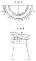
- the cap of this invention in the side view (Fig. 1) showing one example of the cap of this invention, the bottom view (Fig. 2), the A-A' sectional view of Fig. 2 (Fig. 3), the sectional view (Fig. 4) shown by A-B section in a condition in which the cap is mounted on the mouth portion of the container, and the upper surface view (Fig. 5), the cap of this invention, roughly speaking, consists of a cap proper 1 and ring member 2.
- the cap proper 1 is composed of a top panel portion 3 and a skirt portion 4 suspending from the outer circumference of the panel 3.
- protrusions 7 which are engaged with concave portions 6 on the outer circumferential side of the mouth portion 5 of the container are formed in the inner circumference of the skirt portion 4 so that the mouth portion 5 of the container is intimately contacted with the inside surface of the top panel portion 3 to perform sealing.
- the top panel portion 3 has formed therein an inner ring 8 to be engaged with the inner circumferential side of the mouth portion 5 of the container whereby sealing is carried out in the inner circumferential side of the mouth portion 5 of the container to make the sealing more accurate.
- the ring member 2 is not divided and it is provided so as to cover at least a part of the outer surface of the skirt portion 4 in the form of a continuous ring.
- the skirt portion 4 of the cap proper 1 covered with the ring members 2 is provided with a plurality of slits or cuts 9 extending in an axial direction at intervals in a circumferential direction.
- the skirt portion 4 of the cap proper 1 and the ring member 2 are separated via the cutting face 10, and the skirt portion 4 and the ring member 2 are integrally formed via a plurality of frangible bridge portions 11 and unbreakable connecting portions (hinge) 12 which are below the cutting face 10.
- the outer surface of the skirt portion 4 of the cap proper and the inner surface of the ring member 2 are contacted intimately with each other at a portion of the cutting face 10 in a condition in which the cap proper 1 is applied to the mouth portion 5 of the container (Fig. 4).
- An opening tab 13 protruding diametrically outwardly is formed at a part of the ring member 2, and in opening the cap, the tab is held so that the ring member 2 may be pushed up or down.
- a rib 14 extending diametrically is formed in the opening tab 13 to reinforce the opening tab 13 or display its position.
- the number of cuts 9 provided or the transverse gaps of these cuts may be properly determined.
- the number of cuts 9 provided in the skirt portion 4 may differ depending upon the diameter of the cap, but it is preferably 2 to 20, especially 8 to 12.
- the skirt portion 4 of the cap proper By contacting the skirt portion 4 and the ring member 2 intimately at a portion of the cutting face 10, the skirt portion 4 of the cap proper is circumferentially bundled and fixed at least in a cap closed condition with the ring member 2 whereby the skirt portion 4 is prevented from broadening outwardly, and accurate sealing with respect to the mouth portion of the container can be maintained.
- this intimate contacting condition is particularly important.
- the cuts 9 in the skirt portion 4 act to weaken the condition of engagement between the concave portion 6 of the outer circumference of the mouth portion of the container and the protrusion 7 of the skirt portion 4. But when the force of bundling and fixing acts by the ring member 2, the engagement condition becomes firm and accurate.
- the plurality of frangible bridges 11 or the linking portions 12 are provided for linking the skirt portion 4 of the cap proper and the ring member 2 below the cutting face 10, the engraving of the cutting face 10 is prevented from adversely affecting the bridge portions 11 or the connecting portions 12. Because at the time of closing the cap the outer surface of the skirt portion 4 of the cap proper is contacted intimately to the inner surface of the ring member 2 at a portion of the cutting face 10, an outer force is prevented from acting on the breakable bridge portions 11, and the protection of the bridge portions 11 is perfect at the time of closing the cap.
- the intimate contacting condition of the skirt portion 4 of the cap proper and the ring member 2 via the cutting face and the formation of the bridge portions 11 and the connecting portions 12 may be carried out by integrally injection molding or compression molding both, thereafter forming a cut between both by means of a cutter to separate a portion excluding the bridge portions 11 and the connecting portions 12. Therefore the cap of the present invention can be produced with good efficiency and within a short period of time by usually using a mold composed of a core and a cavity, an advantage may be obtained in that the accuracy of each part of the cap is high, and the occurrence of poor goods is small.
- the number of the bridge portions 11 provided between the skirt portion 4 of the cap proper and the ring member 2 is such that the skirt piece 4a between adjoining cuts 9, 9 and the ring member 2 is connected via at least one bridge portion 11.
- the position of providing the bridge portion11 may be variously provided. For example, as shown in Fig. 2, one bridge portion may be provided in a skirt piece 4a, or two bridge portions may be provided on both ends of the skirt piece 4a.
- the position and the number are not particularly limited so long as at the time of closing the cap, the breakage of the bridge portions is prevented and at the time of opening the cap, the bridge portions can be easily broken.
- the cross-sectional area of the bridge portion 11 in its direction of the cutting face 10 of the bridge portion 11 is preferably 0.1 to 0.8 mm 2 , especially 0.2 to 0.4 mm 2 , per one bridge portion.
- An opening tab 13 protruding diametrically outwardly is formed at a part of the ring member 2. This opening tab 13 is positioned in an opposite direction (180° direction) with respect to the connecting portion 12. By pushing up or down the opening tab 13, a divergence occurs between the ring member and the skirt portion at the cutting face, and the bridge portion 11 linking the cap proper 1 and the ring member 2 is cut off under a shearing force.
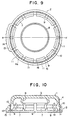
- Fig. 6 shows the state of lifting the ring member 2. Since the cutting face 9 is provided in the skirt portion 4 of the cap proper, when the ring member 2 is removed from the skirt portion 4, the broadening of the skirt piece 4a in a diametrically outward direction becomes free and the cap proper 1 can be easily eliminated from the mouth portion 5 of the container. Hence, the container can be easily opened without using any particular tool. Since in Fig. 6 the ring member 2 is fixed to the cap proper 1 at the connecting portion 12, and is lifted upwardly as a gripping tool, the bridging portion 12 becomes a fulcrum and the cap proper 1 can be easily removed.
- the bridging portions 11 have already been broken and the ring members 2 can be freely moved up or down. From this state, one can already learn that the cap has already been opened. By breakage and bending at the weakening portion 17, it is learned that the cap is already opened, and therefore tamper-evident characteristics are given.
- the lower end 15 of the ring member 2 is positioned below the lower end 16 of the skirt portion 4 of the cap proper.
- the lower end 16 of the skirt portion of the cap proper is hidden by the ring member 2, and therefore, when an attempt is made to open the cap by inserting an instrument into the lower end 16 of the skirt portion, the bridge portions 11 are broken, and the fact of opening the cap can be known and tamper-evident characteristics can be increased.
- the lower end 15 of the ring member 2 suitably extends downwardly over about 0.8 to 1.2 mm below the lower end 16 of the skirt portion.
- a weakened portion for displaying cap opening such as a cut 17, in a lower portion of the ring member in a direction of about 90° with respect to the opening tab 13 of the ring member 2.
- a partly weakened portion namely a groove 18, may be formed on the upper portion of the connecting portion 12, or a weakened portion, namely a cut 19, may be formed in both ends of a lower portion of the connecting portion 12.
- a partial weakened portion 20 may be formed in the top panel portion 3 on the side of the connecting portion 12. Therefore, when an unfair opening of the cap is carried out by using a tool from the side of the connecting portion 12, the top panel portion 3 of the cap is deformed or broken, and one can learn that the cap has been unfairly opened.
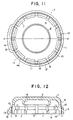
- an inner ring 8 is formed to have an inclined end edge so that the inner ring 8 is relatively long at 21 on the side of an opening tab 13, and is relatively short at 22 on the side of a connecting portion 12.
- the opening of the cap proper is carried out from the side of the connecting portion 12 by lifting the ring member 2.
- the venting of a gas from the shorter inner ring 22 is carried out effectively, and the blowing of the contents, that is to say the blowing off, can be prevented effectively.
- the above-mentioned prevention of blow off can be effectively carried out by providing a weakened portion 23 on the inner surface of the inner ring 22 on the side of the connecting portion. This makes it easy to transform the inner ring 22 on the side of the connecting portion, and the gas inside the container is effectively released via the inner ring 22.
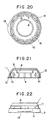
- a gas-barrier material 24 may be provided by insert molding in the top panel portion of the inside surface of the inner ring 8. This makes it possible to prevent permeation of the gas through the plastic cap wall and to increase the preservability of the contents.
- the gas-barrier material include, for example, metal foils such as aluminum foil, and a gas-barrier resin such as an ethylene /vinyl alcohol copolymer, a vinyl chloride resin, a vinylidene chloride resin, nylon resin, and gas-barrier polyesters.
- an oxygen absorbing layer may be provided in the top panel portion.
- oxygen absorbing layer iron-type oxygen absorbing agents, for example, dispersed in a resin may be used.
- a total circumferential or intermittent ring 25 may be formed which protrudes upwardly into an outer cylindrical portion of the top panel portion 3.
- the upper portion of the cut 9 is exposed to an outside portion as best shown in Fig. 1.
- the caps of these examples are advantageous in that the contents adhering to the outer circumference of the mouth portion at the time of filling the contents can be washed and removed through the cuts 9.
- the lower end 15 of the ring member 2 and the lower end 16 of the skirt portion 4 of the cap proper may be provided so as to be positioned on the same horizontal plane. In this case, it is possible to prevent effectively the addition of a load on the bridge portion 11 at the time of loading caps and the consequent breakage of the bridge portion 11.
- the opening tab is not limited to one piece, but two tabs may be provided in a symmetrical position. Furthermore, more than two tabs may be provided.
- the cuts 9 may be provided so that they are not exposed into the outer circumference of the skirt portion.
- the constructions of the individual parts have been the same as explained hereinabove.
- the outer upper portion 26 of the cut 9 are provided so that it does not reach the outer surface of the skirt portion 4, and therefore, the cut 9 is covered completely with the upper surface of the skirt portion.
- an advantage is achieved in that dirt is prevented from entering in the cut 9 and the cap is sanitary.
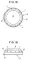
- the bridge portion 11 and the connecting portion 12 are provided below the cutting face 10, but in the present invention, the bridge portion and the connecting portion may be provided above the cutting face.
- the constructions of the individual parts are the same as explained hereinabove, but the bridge portion 11 and the connecting portion 12 are formed above the cutting surface 10.
- the bridge portion 11 can be seen from outside at a first sight, and it becomes advantageous that the fact of opening becomes clearer.
- the resin used to form the cap are various plastics, such as low-, medium- and high-density polyethylenes, linear low-density polyethylene, polypropylene, thermoplastic polyesters, polyamides, styrene resins, and ABS resin.
- plastics such as low-, medium- and high-density polyethylenes, linear low-density polyethylene, polypropylene, thermoplastic polyesters, polyamides, styrene resins, and ABS resin.
- the plastic cap of this invention is prepared by using the above resins, and usually integrating the cap proper and ring member by means of injection molding, compression molding, etc.
- the cutting face is usually produced by applying a cutting processing after the molding step. Of course, a cutting surface can be formed simultaneously with the molding step.
- a liner may be applied to the cap proper.
- low-density polyethylene ethylene copolymers, various rubber or thermoplastic elastomers, acrylic resin plastisol and vinyl chloride resin plastisol.
- the above-mentioned constructions make it possible to form a sealing structure having sealing reliability at the time of closing the cap, and to open the cap easily without using any particular tool at the time of cap opening.
- this is advantageous that tamper-evident characteristics are imparted.
- the ring member protects the skirt portion of the cap proper, in the state of a closure being closed, the ring member contacts intimately with the outer surface of the skirt of the cap proper to maintain sealability, and at the time of opening the cap, the skirt portion can be easily eliminated from the mouth portion of the container as a result of removing the ring member.
- the ring member has tamper-evident characteristics.
Landscapes
- Engineering & Computer Science (AREA)
- Mechanical Engineering (AREA)
- Closures For Containers (AREA)
- Pressure Vessels And Lids Thereof (AREA)
Applications Claiming Priority (3)
| Application Number | Priority Date | Filing Date | Title |
|---|---|---|---|
| JP4443195 | 1995-03-03 | ||
| JP44431/95 | 1995-03-03 | ||
| JP04443195A JP3492007B2 (ja) | 1995-03-03 | 1995-03-03 | キャップ |
Publications (3)
| Publication Number | Publication Date |
|---|---|
| EP0729895A2 EP0729895A2 (en) | 1996-09-04 |
| EP0729895A3 EP0729895A3 (en) | 1997-02-26 |
| EP0729895B1 true EP0729895B1 (en) | 2003-11-05 |
Family
ID=12691312
Family Applications (1)
| Application Number | Title | Priority Date | Filing Date |
|---|---|---|---|
| EP96301387A Expired - Lifetime EP0729895B1 (en) | 1995-03-03 | 1996-02-29 | Resin cap |
Country Status (7)
| Country | Link |
|---|---|
| EP (1) | EP0729895B1 (ca) |
| JP (1) | JP3492007B2 (ca) |
| KR (1) | KR100436630B1 (ca) |
| CN (1) | CN1071254C (ca) |
| DE (1) | DE69630551T2 (ca) |
| IN (1) | IN192642B (ca) |
| SA (1) | SA96170026A (ca) |
Families Citing this family (11)
| Publication number | Priority date | Publication date | Assignee | Title |
|---|---|---|---|---|
| DE19712364A1 (de) * | 1997-03-25 | 1998-10-01 | Bericap Gmbh & Co Kg | Schnappverschluß |
| US5860545A (en) * | 1997-04-17 | 1999-01-19 | The Procter & Gamble Company | Plastic bottle closure with single relief recess proximate to the lower peripheral edge of said closure |
| JP5294812B2 (ja) * | 2008-11-27 | 2013-09-18 | 株式会社丸一 | エアゾール容器用キャップ |
| JP5458203B2 (ja) * | 2013-04-26 | 2014-04-02 | 株式会社丸一 | エアゾール容器用キャップ |
| JP6322446B2 (ja) * | 2014-03-04 | 2018-05-09 | 日本クロージャー株式会社 | 合成樹脂製容器蓋 |
| JP6254470B2 (ja) * | 2014-03-26 | 2017-12-27 | 日本クロージャー株式会社 | 合成樹脂製容器蓋 |
| JP6317153B2 (ja) * | 2014-03-26 | 2018-04-25 | 日本クロージャー株式会社 | 合成樹脂製容器蓋 |
| JP6294723B2 (ja) * | 2014-03-26 | 2018-03-14 | 日本クロージャー株式会社 | 容器と容器蓋との組み合わせ |
| JP6254471B2 (ja) * | 2014-03-26 | 2017-12-27 | 日本クロージャー株式会社 | 合成樹脂製容器蓋 |
| JP6468793B2 (ja) * | 2014-10-21 | 2019-02-13 | 日本クロージャー株式会社 | 合成樹脂製容器蓋 |
| JP6438824B2 (ja) * | 2015-03-31 | 2018-12-19 | 日本クロージャー株式会社 | 合成樹脂製容器蓋 |
Family Cites Families (9)
| Publication number | Priority date | Publication date | Assignee | Title |
|---|---|---|---|---|
| FR1197164A (fr) * | 1958-05-27 | 1959-11-27 | Rical Sa | Capsule pour bouchage de bouteilles devant résister à une pression interne |
| US3300073A (en) * | 1963-12-05 | 1967-01-24 | Benz Erwin | Elastic closure for a container opening |
| FR2141585B1 (ca) * | 1971-06-17 | 1976-03-19 | Somepla Sa | |
| US3986627A (en) * | 1974-12-17 | 1976-10-19 | Refil Aktiengesellschaft | Closure |
| DE3017839A1 (de) * | 1980-05-09 | 1982-11-25 | Hans 5463 Unkel Simon | Verschlusskappe fuer flaschen |
| GB2085854B (en) * | 1980-09-26 | 1985-03-13 | Johnsen Jorgensen Plastics Ltd | An improved container closure |
| GB2086361B (en) * | 1980-09-26 | 1984-07-18 | Johnsen Jorgensen Plastics Ltd | An improved container closure |
| CH673629A5 (ca) * | 1987-02-23 | 1990-03-30 | Asepta Ag | |
| CN1068286C (zh) * | 1992-06-22 | 2001-07-11 | 李贞旻 | 合成树脂制成的瓶盖 |
-
1995
- 1995-03-03 JP JP04443195A patent/JP3492007B2/ja not_active Expired - Fee Related
-
1996
- 1996-02-29 DE DE69630551T patent/DE69630551T2/de not_active Expired - Lifetime
- 1996-02-29 KR KR1019960005626A patent/KR100436630B1/ko not_active Expired - Lifetime
- 1996-02-29 EP EP96301387A patent/EP0729895B1/en not_active Expired - Lifetime
- 1996-03-01 IN IN323MA1996 patent/IN192642B/en unknown
- 1996-03-04 CN CN96102936A patent/CN1071254C/zh not_active Expired - Fee Related
- 1996-05-21 SA SA96170026A patent/SA96170026A/ar unknown
Also Published As
| Publication number | Publication date |
|---|---|
| DE69630551D1 (de) | 2003-12-11 |
| SA96170026A (ar) | 2005-12-03 |
| EP0729895A2 (en) | 1996-09-04 |
| JPH08244802A (ja) | 1996-09-24 |
| KR100436630B1 (ko) | 2004-07-30 |
| IN192642B (ca) | 2004-05-08 |
| CN1137012A (zh) | 1996-12-04 |
| DE69630551T2 (de) | 2004-09-23 |
| KR960034023A (ko) | 1996-10-22 |
| EP0729895A3 (en) | 1997-02-26 |
| CN1071254C (zh) | 2001-09-19 |
| JP3492007B2 (ja) | 2004-02-03 |
Similar Documents
| Publication | Publication Date | Title |
|---|---|---|
| US5762217A (en) | Resin cap | |
| EP0949156B1 (en) | Plastic cap | |
| US4487326A (en) | Carbonated beverage package | |
| EP0796801B1 (en) | A Hinge cap separable from bottle at the time of disposal | |
| EP0827913B1 (en) | A cap separable from bottle at the time of disposal | |
| US4032029A (en) | Tamper-proof bottle cap and container | |
| JPH11502491A (ja) | 係留バンドを備えたピルファープルーフ蓋 | |
| EP0729895B1 (en) | Resin cap | |
| US5857580A (en) | Bottle and closure with separable cap and plug elements | |
| JP3762470B2 (ja) | 樹脂製キャップ | |
| US4355729A (en) | Single service childproof closure | |
| US3608765A (en) | Neck for widemouth jar and cap therefor | |
| US6095354A (en) | Child resistant closure and container | |
| EP0691281B1 (en) | Container closure assembly | |
| JP4349698B2 (ja) | プラスチックキャップ | |
| JP5389550B2 (ja) | 打栓式開閉容易キャップ | |
| US4817807A (en) | Tamper-evident container | |
| JP3748604B2 (ja) | 分別廃棄容易な合成樹脂製容器蓋 | |
| JP4349680B2 (ja) | 樹脂製キャップ | |
| US4744483A (en) | Tamper evident cover | |
| JP4762426B2 (ja) | 分別廃棄可能なキャップ | |
| JP4514437B2 (ja) | ベント機能を有するプラスチックキャップ | |
| JP4416199B2 (ja) | 樹脂製キャップ | |
| JPH10245052A (ja) | 樹脂製キャップ | |
| JP3875421B2 (ja) | 開口仮封止栓付缶 |
Legal Events
| Date | Code | Title | Description |
|---|---|---|---|
| PUAI | Public reference made under article 153(3) epc to a published international application that has entered the european phase |
Free format text: ORIGINAL CODE: 0009012 |
|
| AK | Designated contracting states |
Kind code of ref document: A2 Designated state(s): AT BE |
|
| AX | Request for extension of the european patent |
Free format text: SI |
|
| RAX | Requested extension states of the european patent have changed |
Free format text: SI |
|
| RBV | Designated contracting states (corrected) |
Designated state(s): DE GB |
|
| PUAL | Search report despatched |
Free format text: ORIGINAL CODE: 0009013 |
|
| AK | Designated contracting states |
Kind code of ref document: A3 Designated state(s): DE GB |
|
| AX | Request for extension of the european patent |
Free format text: SI |
|
| 17P | Request for examination filed |
Effective date: 19970411 |
|
| 17Q | First examination report despatched |
Effective date: 20011019 |
|
| GRAH | Despatch of communication of intention to grant a patent |
Free format text: ORIGINAL CODE: EPIDOS IGRA |
|
| GRAH | Despatch of communication of intention to grant a patent |
Free format text: ORIGINAL CODE: EPIDOS IGRA |
|
| GRAA | (expected) grant |
Free format text: ORIGINAL CODE: 0009210 |
|
| DAX | Request for extension of the european patent (deleted) | ||
| AK | Designated contracting states |
Kind code of ref document: B1 Designated state(s): DE GB |
|
| REG | Reference to a national code |
Ref country code: GB Ref legal event code: FG4D |
|
| REF | Corresponds to: |
Ref document number: 69630551 Country of ref document: DE Date of ref document: 20031211 Kind code of ref document: P |
|
| PLBE | No opposition filed within time limit |
Free format text: ORIGINAL CODE: 0009261 |
|
| STAA | Information on the status of an ep patent application or granted ep patent |
Free format text: STATUS: NO OPPOSITION FILED WITHIN TIME LIMIT |
|
| GBPC | Gb: european patent ceased through non-payment of renewal fee | ||
| 26N | No opposition filed |
Effective date: 20040806 |
|
| REG | Reference to a national code |
Ref country code: GB Ref legal event code: 728V |
|
| REG | Reference to a national code |
Ref country code: GB Ref legal event code: 728Y |
|
| PGFP | Annual fee paid to national office [announced via postgrant information from national office to epo] |
Ref country code: DE Payment date: 20130220 Year of fee payment: 18 Ref country code: GB Payment date: 20130228 Year of fee payment: 18 |
|
| REG | Reference to a national code |
Ref country code: DE Ref legal event code: R119 Ref document number: 69630551 Country of ref document: DE |
|
| GBPC | Gb: european patent ceased through non-payment of renewal fee |
Effective date: 20140228 |
|
| REG | Reference to a national code |
Ref country code: DE Ref legal event code: R119 Ref document number: 69630551 Country of ref document: DE Effective date: 20140902 |
|
| PG25 | Lapsed in a contracting state [announced via postgrant information from national office to epo] |
Ref country code: GB Free format text: LAPSE BECAUSE OF NON-PAYMENT OF DUE FEES Effective date: 20140228 Ref country code: DE Free format text: LAPSE BECAUSE OF NON-PAYMENT OF DUE FEES Effective date: 20140902 |