EP0723830A2 - Werkzeughalter - Google Patents
Werkzeughalter Download PDFInfo
- Publication number
- EP0723830A2 EP0723830A2 EP95118711A EP95118711A EP0723830A2 EP 0723830 A2 EP0723830 A2 EP 0723830A2 EP 95118711 A EP95118711 A EP 95118711A EP 95118711 A EP95118711 A EP 95118711A EP 0723830 A2 EP0723830 A2 EP 0723830A2
- Authority
- EP
- European Patent Office
- Prior art keywords
- fluid
- supply hole
- tool
- fluid supply
- oil
- Prior art date
- Legal status (The legal status is an assumption and is not a legal conclusion. Google has not performed a legal analysis and makes no representation as to the accuracy of the status listed.)
- Withdrawn
Links
- 239000012530 fluid Substances 0.000 claims abstract description 241
- 230000001105 regulatory effect Effects 0.000 claims abstract description 22
- 238000004891 communication Methods 0.000 claims description 7
- 230000009467 reduction Effects 0.000 claims description 6
- 238000011038 discontinuous diafiltration by volume reduction Methods 0.000 claims description 4
- 230000004044 response Effects 0.000 claims description 2
- 239000010730 cutting oil Substances 0.000 description 44
- 238000012856 packing Methods 0.000 description 16
- 239000003921 oil Substances 0.000 description 14
- 230000009471 action Effects 0.000 description 12
- 239000011435 rock Substances 0.000 description 6
- 239000002826 coolant Substances 0.000 description 2
- 238000005520 cutting process Methods 0.000 description 2
- 239000000428 dust Substances 0.000 description 2
- 230000000694 effects Effects 0.000 description 2
- 238000000034 method Methods 0.000 description 2
- 230000008569 process Effects 0.000 description 2
- 239000011347 resin Substances 0.000 description 2
- 229920005989 resin Polymers 0.000 description 2
- 230000003247 decreasing effect Effects 0.000 description 1
- 230000007547 defect Effects 0.000 description 1
- 238000007730 finishing process Methods 0.000 description 1
- 230000007257 malfunction Effects 0.000 description 1
- 239000000463 material Substances 0.000 description 1
- 239000002184 metal Substances 0.000 description 1
- 239000003595 mist Substances 0.000 description 1
- 238000003825 pressing Methods 0.000 description 1
- 238000007789 sealing Methods 0.000 description 1
Images


Classifications
-
- B—PERFORMING OPERATIONS; TRANSPORTING
- B23—MACHINE TOOLS; METAL-WORKING NOT OTHERWISE PROVIDED FOR
- B23Q—DETAILS, COMPONENTS, OR ACCESSORIES FOR MACHINE TOOLS, e.g. ARRANGEMENTS FOR COPYING OR CONTROLLING; MACHINE TOOLS IN GENERAL CHARACTERISED BY THE CONSTRUCTION OF PARTICULAR DETAILS OR COMPONENTS; COMBINATIONS OR ASSOCIATIONS OF METAL-WORKING MACHINES, NOT DIRECTED TO A PARTICULAR RESULT
- B23Q11/00—Accessories fitted to machine tools for keeping tools or parts of the machine in good working condition or for cooling work; Safety devices specially combined with or arranged in, or specially adapted for use in connection with, machine tools
- B23Q11/10—Arrangements for cooling or lubricating tools or work
- B23Q11/1084—Arrangements for cooling or lubricating tools or work specially adapted for being fitted to different kinds of machines
-
- B—PERFORMING OPERATIONS; TRANSPORTING
- B23—MACHINE TOOLS; METAL-WORKING NOT OTHERWISE PROVIDED FOR
- B23Q—DETAILS, COMPONENTS, OR ACCESSORIES FOR MACHINE TOOLS, e.g. ARRANGEMENTS FOR COPYING OR CONTROLLING; MACHINE TOOLS IN GENERAL CHARACTERISED BY THE CONSTRUCTION OF PARTICULAR DETAILS OR COMPONENTS; COMBINATIONS OR ASSOCIATIONS OF METAL-WORKING MACHINES, NOT DIRECTED TO A PARTICULAR RESULT
- B23Q1/00—Members which are comprised in the general build-up of a form of machine, particularly relatively large fixed members
- B23Q1/0009—Energy-transferring means or control lines for movable machine parts; Control panels or boxes; Control parts
- B23Q1/0018—Energy-transferring means or control lines for movable machine parts; Control panels or boxes; Control parts comprising hydraulic means
-
- B—PERFORMING OPERATIONS; TRANSPORTING
- B23—MACHINE TOOLS; METAL-WORKING NOT OTHERWISE PROVIDED FOR
- B23B—TURNING; BORING
- B23B2231/00—Details of chucks, toolholder shanks or tool shanks
- B23B2231/24—Cooling or lubrication means
-
- Y—GENERAL TAGGING OF NEW TECHNOLOGICAL DEVELOPMENTS; GENERAL TAGGING OF CROSS-SECTIONAL TECHNOLOGIES SPANNING OVER SEVERAL SECTIONS OF THE IPC; TECHNICAL SUBJECTS COVERED BY FORMER USPC CROSS-REFERENCE ART COLLECTIONS [XRACs] AND DIGESTS
- Y10—TECHNICAL SUBJECTS COVERED BY FORMER USPC
- Y10T—TECHNICAL SUBJECTS COVERED BY FORMER US CLASSIFICATION
- Y10T279/00—Chucks or sockets
- Y10T279/17—Socket type
- Y10T279/17111—Fluid-conduit drill holding
-
- Y—GENERAL TAGGING OF NEW TECHNOLOGICAL DEVELOPMENTS; GENERAL TAGGING OF CROSS-SECTIONAL TECHNOLOGIES SPANNING OVER SEVERAL SECTIONS OF THE IPC; TECHNICAL SUBJECTS COVERED BY FORMER USPC CROSS-REFERENCE ART COLLECTIONS [XRACs] AND DIGESTS
- Y10—TECHNICAL SUBJECTS COVERED BY FORMER USPC
- Y10T—TECHNICAL SUBJECTS COVERED BY FORMER US CLASSIFICATION
- Y10T408/00—Cutting by use of rotating axially moving tool
- Y10T408/44—Cutting by use of rotating axially moving tool with means to apply transient, fluent medium to work or product
- Y10T408/45—Cutting by use of rotating axially moving tool with means to apply transient, fluent medium to work or product including Tool with duct
-
- Y—GENERAL TAGGING OF NEW TECHNOLOGICAL DEVELOPMENTS; GENERAL TAGGING OF CROSS-SECTIONAL TECHNOLOGIES SPANNING OVER SEVERAL SECTIONS OF THE IPC; TECHNICAL SUBJECTS COVERED BY FORMER USPC CROSS-REFERENCE ART COLLECTIONS [XRACs] AND DIGESTS
- Y10—TECHNICAL SUBJECTS COVERED BY FORMER USPC
- Y10T—TECHNICAL SUBJECTS COVERED BY FORMER US CLASSIFICATION
- Y10T409/00—Gear cutting, milling, or planing
- Y10T409/30—Milling
- Y10T409/303976—Milling with means to control temperature or lubricate
- Y10T409/304032—Cutter or work
Definitions
- the present invention relates to a holder for holding a tool of the type in which fluid such as cutting oil, coolant, and mist including air and coolant is spouted to a workpiece to be worked through a fluid channel located at the tip end or nearby.
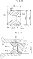
- Such tools and tool holders as shown in Fig. 16 are known as such which supplies cutting oil etc. to the workpiece particularly on the portion to be worked from the tip end of the tool through a fluid channel provided inside the tool.
- the tool holder portion of the tool holder is constituted from a collet 22, a tip end opening 23a of a cuill 23 and a rock nut 24.
- the collet 22 comprises a tip portion 22a and a rear end 22b both tapered on the outer circumference, and several split grooves are provided in an axial direction of the collet to reduce its diameter.
- the inner surface of the tip end opening 23a is formed in a tapered manner and the outer circumference thereof is provided with a male screw 23b.
- the inner surface 24a of the tip of the rock nut 24 is formed in a tapered manner and the inner surface of the rear end is tapped to form a female screw 24b.
- a straight shank portion 21b of an oil-through-drill 21 is coupled with the tip end opening 23a of the cuill 23 through the collet 22.
- the rock nut 24 abuts against the tip end 22a of the collet 22 on the inner surface 24a of the tip end, and by a female screw 24b it screws together with male screw 23b. Since the collet 22 and the rock nut 24 abut against the surface 24a of the tip end, in accordance with the screwed amount of the rock nut 24 into the tip end opening 23a of the cuill 23, the rear end 22b of the collet 22 is coupled with the inner side of the tip end opening 23a of the cuill 23. Since the inner surface of the tip end opening 23a of the cuill 23 is formed in a tapered manner, the collet 22 coupled inside is reduced in its diameter by being reduced in the spacing between the grooves of the plurality of split grooves provided in an axial direction.
- the straight shank 21b of the oil-through-drill 21 has a diameter identical with the inner diameter or less of the fluid supply hole 23e of the cuill 23, which is clamped with the collet 22 along with the reduction of the diameters of the tip end 22a and the rear end 22b of the collet 22, so that the oil-through-drill is fastened inside the fluid supply hole 23e of the cuill.
- the pressure of the fluid such as cutting oil is increased, from, for instance, a gap between the fluid supply hole 23e and the straight shank 21b of the oil-through-drill 21 and the gap which belongs to the tool holding elements such as a plurality of split grooves provided on the collet 22, a great amount of cutting oil under increased pressure leaks, so that a given amount of fluid can not be spouted from the tip end 21a.
- the oil seal packing is configured like a hat, the tip end 50a of which provides an opening 50b.
- the tip end 50a touches the end of the oil-through-drill 21, and an annular circumferential trailing end 50c adheres to the fluid supply hole 23e.
- the circumference of the trailing end 50c adheres closely to the inner surface of the cuill 23 adjacent to the fluid supply hole 23e and the tip end 50a adheres closely to the inner surface of the collet 22 adjacent to the end of the oil-through-drill 21. So that the leak of the fluid from the slit grooves is prevented.
- the oil seal packing 50 shown in Fig. 17 is limited in its mounting position due to the collet 22, so that the position of the oil seal packing can not be regulated. Accordingly, when fitting a tool, the end of the tool has to adhere precisely to the oil-seal-packing. Further, before fastening the oil-through-drill 21, if a little fluid leaking occurs and that leaked fluid attaches on the slit grooves of the collet 22, those slits may collect cut chips and some dusts. And when replacing such oil-through-drill 21, it becomes necessary to wash it. In addition, to avoid such collection, some precautions are needed, such as covering the tool with a dust cover to prevent outer things from being adhered.
- the present invention has been made in the light of the above problems, and the objects thereof are to prevent from unnecessary leaking of the fluid from the gaps which the constitutional elements of the tool holding portion have or which are formed in the constitutional elements between the tool and the tool holding portion by pressing a seal member in a fluid supply hole against the end of the tool where fluid channels are opened, making the highly pressurized fluid supplied in the tool holder in communication with a fluid channel of a tool and sealing the inner surface of the fluid supply hole and the end of the tool, and to secure a necessary supply amount of fluid to the end of the tool and if necessary to supply a regulated amount of fluid to said gaps.
- a tool holder which holds a tool at the end opening connected to the fluid supply hole having a given inner diameter through a collet and can supply the fluid to the supply channels of the tool from said fluid supply hole, comprises in the fluid supply hole a regulator which regulates an amount of fluid flowing to said fluid channels of the tool and an amount of fluid flowing to the gap between the inner surface of the fluid supply hole and the outer surface of the tool.
- said regulator defined in the first aspect of the invention is a seal member which abuts against the end of said tool in said fluid supply hole by free sliding in the longitudinal direction in the fluid supply hole due to the pressure of the fluid supplied into the fluid supply hole and also against the inner surface of the fluid supply hole.
- said regulator defined in the first aspect of the invention is a seal member having a main channel to supply the fluid to the channels of the tool and at least one of said member and said tool holder is provided with a bypass to introduce the fluid to the gap between the inner surface of the fluid supply hole and the outer surface of the tool.
- said tool holder defined in any one of the second and the third aspects of the invention is provided with a pressure reducing means which prevent the pressure increasing due to the volume reduction of the space formed with the seal member and the tool holding portion of the tool in accordance with the sliding of the seal member.
- said seal member of the tool holder defined in any one of the second through fourth aspects is provided with a diameter-expandable portion which expands due to the pressure of the fluid acting on the seal member and comes close to the inner surface of the fluid supply hole.
- an outer diameter portion of the seal member of the tool holder defined in any one of the second through the fifth aspects is provided with a projection having a diameter larger than the diameter of the fluid supply hole.
- a necessary amount of fluid to the tip end of the tool is secured, in addition if necessary, a necessary flow amount of the fluid may be supplied to the gaps such as between the elements of the tool holding portion or between the elements of the tool and the tool holding portion.
- the seal member upon receiving the fluid pressure, abuts against the end of the tool and also against the inner surface of the fluid supply hole, thereby said fluid is supplied to the fluid channels of the tool and a necessary fluid amount to the tip end of the tool is secured.
- the seal member comes close to the end of the tool in the fluid supply hole and said fluid is supplied to the fluid channels of the tool, it becomes possible to secure the necessary fluid amount to the end of the tool, and further, due to the bypass provided on at least either one of the seal member or the tool holder, a necessary amount of the fluid is supplied also to the gap between the inner surface of the fluid supply hole and the outer surface of the tool.
- the pressure reduction means can prevent the increasing of the pressure due to the reduction of the volume of the space formed with the seal member and the tool holding portion of the tool holder in accordance with the sliding of the seal member in the fluid supply hole of the tool holder, the pressure increased due to the volume reduction of the volume overwhelms the supply pressure of the fluid, thereby the sliding of the seal member is affected little due to the fluid supply to increase the close adhesion between the seal member and the end of the tool.
- Fig. 1 is a schematic view of the setting status of a seal block of a tool holder in section according to the first embodiment of the present invention.
- Fig. 2 is a schematic view of the setting status of a seal block of a tool holder in section according to the first embodiment of the present invention.
- Fig. 3 is a sectional view of the single seal block shown in Fig. 1.
- Fig. 4 is a sectional view of a seal block having a conic operation surface.
- Fig. 5 is a sectional view of a seal block having an annular groove-like operation surface.
- Fig. 6 is a sectional view showing the sliding status of the seal block.
- Fig. 7 is a sectional view showing a close adhesion status of a seal block.
- Fig. 8 is a sectional view showing a close adhesion status of a seal block.
- Fig. 9 is a schematic view of the second embodiment of the seal block according to the present invention, (a) shows an operation side thereof, and (b) shows it in section.
- Fig. 10 is a schematic view showing a variation from the second embodiment, (a) shows a view from the operation side and (b) shows a sectional view along A - A line of (a).
- Fig. 11 is a schematic view of a further variation of the seal block of the second embodiment, (a) shows its abutting side and (b) shows its sectional view.
- Fig. 12 is a schematic view of the setting status of a seal block of a tool holder in section according to the third embodiment of the present invention.
- Fig. 13 is a sectional view of a seal block according to the fourth embodiment of the present invention.
- Fig. 14 is a sectional view of the setting status of the seal block shown in Fig. 13 to the tool holder.
- Fig. 15 is a sectional view of a pressure reduction means in the fifth embodiment of the present invention.
- Fig. 16 is a sectional view of a conventional tool holder.
- Fig. 17 is a sectional view of the essential portion of a tool holder having a conventional oil seal packing.
- Fig. 18 is a sectional view of a conventional regulatable oil seal packing.
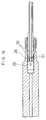
- Figs. 1 and 2 illustrate an outline of the tool holder in which the present invention is worked.
- the tool holding portion of this tool holder is constituted with a collet 2, the tip end opening 3a of a drill chuck 3.
- the collet 2 comprises a tip end portion 2a, the outer surface of which is formed in a tapered manner toward the tip and a rear portion 2b, the collet 2 is provided with several split grooves along the axial direction of the collet 2 in order to reduce its diameter.
- the inner surface of the tip end opening 3a of the drill chuck 3 is formed in a tapered manner, on its outer surface of the tip end opening 3a a male screw 3b is threaded.
- the inner surface 4a of the tip end of a lock nut 4 is formed in a tapered manner, and on the inner surface of the rear portion a female screw 4b is threaded.
- the straight shank portion 1b of the oil-through-drill 1 is coupled with the tip end opening 3a of the drill chuck 3 as a tool holder through the collet 2.
- the lock nut 4 abuts against the tip end portion 2a of the collet 2 with its inner surface 4a, and the female screw 4b engages with the male screw 3b of the drill chuck 3.
- the collet 2 and the lock nut 4 abuts against each other with the tip end portion 2a and the inner surface 4a of the tip end portion of the lock nut 4, in accordance with the screwed stroke of the lock nut 4 into the tip opening 3a of the drill chuck 3, the rear end portion 2b of the collet 2 is inserted into the inner side of the tip end opening portion 3a of the drill chuck 3. Since the inner surface of the tip end opening 3a of the drill chuck 3 is formed in a tapered manner, the collet 2 to be inserted inside the collet 2 is reduced in its diameter by narrowing the split width of the plural grooves.
- the diameter of the straight shank 1b of the oil-through-drill 1 is identical with or smaller than the inner diameter of the fluid supply hole 3d, but it is clamped with the collet 2 in accordance with the diameter reduction of the tip end 2a of the collet 2 and the rear end portion 2b and the oil-through-drill 1 is fastened inside the fluid supply hole 3d of the drill chuck 3. Accordingly, between the straight shank 1b and the fluid supply hole 3d, a gap by the diameter difference between the straight shank 1b and the fluid supply hole 3d is formed.
- the drill chuck 3 is coupled with a cuill 6 in the straight shank 3c through a collet 5, and the drill chuck 3 is fastened on the cuill 6 by a lock nut 7 which is screwed in the outer screw portion 6a of the cuill 6.
- a taper shank 6b of the cuill 6 is coupled with a main shaft 8
- the cuill 6 is drawn into the main shaft 8 through a pull stud 9 screwed in a female screw 6c of the rear end of the cuill 6 and fastened.
- the oil-through-drill 1 has a fluid channel 1c inside, and the drill chuck 3, the cuill 6 and pull stud 9 are provided with the fluid supply holes 3d, 6d and 9a respectively, thereby, when the cuill 6 is drawn in the inside the main shaft 8 and fastened, a supply tube 10 inside the main shaft is in communication with the fluid supply holes 9a, 6d, 3d and the fluid channel 1c and a cutting oil can spout from the tip end 1a of the tool.
- the present embodiment is explained based on a fluid supply system in which, as shown in Fig. 1, a fluid is supplied from the supply tube 10 within the main shaft 8 to the fluid supply hole 6d of the cuill 6 through the fluid supply hole 9a of the pull stud 9, but it may be a fluid supply system in which, as shown in Fig. 2, a fluid is supplied from the supply tube 110 within the main shaft 108 to the fluid supply hole 106d of the cuill 106.
- the similar members or parts as well as in the fluid supply system described in Fig. 1 are designated by the identical signs and the explanations thereof are omitted.
- a tool holder a case where a drill chuck shown in Figs. 1 and 2 is used, it may be a cuill shown in Fig. 7 as a tool holder in place of a drill chuck.
- a seal block 11 as a regulator means to regulate the proportion of the flowing amount between the fluid amount flowing into the fluid channel 1c of the oil-through-drill 1 and the fluid amount flowing into the gap portion between the fluid supply hole 3d and the straight shank portion 1b of the oil-through-drill 1, is provided slidably toward an axial direction of the fluid supply hole 3d.
- the outer configuration of the seal block 11 is approximately identical with the inner shape of the fluid supply hole, and the dimension of the outer circumference of the seal block is approximately identical with the dimension of the inner surface of the fluid supply hole.
- the fluid supply hole and the seal block are circle in section and the outer dimension of the seal block is a little smaller than the dimension of the inner circumference of the fluid supply hole.
- a fluid channel 11a is provided in an identical direction with a longitudinal direction of a fluid supply hole, and the shape of the abutting side 11b which abuts against the rear end of the oil-through-drill 1 is formed conical, and this outer circumference of the rear end of the oil-through-drill 1 adheres close to the conical inner circumference of the seal block.
- the fluid pressure action face side 11c of the seal block 11 is formed plane and receives the fluid pressure.
- the material of the seal block 11 may be a metal or a metal-partially including one, but it is preferable to use a resin easy to be deformed elastically. In this embodiment, a gum to be deformed elastically is used.
- the shape of the seal block is shown in Fig. 4 as 111 indicative of the same, which comprises a diameter enlarging portion which is enlarged in response to the pressure of a cutting oil.
- a fluid channel 111a is formed in the identical direction with the longitudinal direction of the fluid supply channel hole, and the shape of the abutting face side 111b of the seal block 11, which abuts against the rear end of the oil-through-drill 1, is formed conical, and the outer circumference of the oil-through-drill 1 adheres close to the conical inner face.
- the shape of the seal block 111 in the fluid pressure action face side 111c is formed conical, it adheres close to the inner surface of the fluid supply hole of the oil-through-drill 1 by the enlarging of the action face of outer circumference 111d.
- Fig. 6 a status where the seal block 11 slides in the fluid supply hole 3d of the drill chuck 3 toward the axial direction of the fluid supply hole is shown.
- the seal block 11 stays at an arbitrary position 12a in the fluid supply hole 3d.
- the seal block 11 is quickly slidden by the pressure of the supplied cutting oil toward the oil-through-drill 1 held, and reaches the position 12b where the conical inner surface of the seal block 11 adheres close to the outer circumference of the rear portion of the oil-through-drill 1 within the fluid supply hole 3d.
- the seal block 11 continues to be pressed by the pressure action of the cutting oil after the close adhesion to the rear portion of the oil-through-drill 1, so that it is elastically deformed as shown in Fig. 7 to be compressed in an axial direction and enlarged in a diameter direction. By this diametral enlarging, the seal block 11 adheres close to the inner surface of the drill chuck 3.
- a fluid channel 11a is provided in an axial direction, so that the supplied cutting oil is supplied through the fluid supply channel 11a to the close adhesion portion where the rear portion of the oil-through-drill 1 and the abutting face side 11b of the seal block 11 adhere a close, then the cutting oil is carried to the fluid channel 1c. Accordingly, such regulation as the flowing amount of the fluid to the fluid channel 1c is in maximum, and the flowing amount to the gap portion between the straight shank portion 1b of the oil-through-drill 1 and the fluid supply hole 3d of the drill chuck 3 is in minimum can be carried out.
- the seal block 111 shown in Fig. 4 as shown in Fig. 8 the seal block 111 is compressed in an axial direction and enlarged in a diametral direction, further the diameter enlarging portion 111d is also enlarged to increase the close adhesion to the inner surface of the fluid supply 3d of the drill chuck 3.
- the seal block shown in Fig. 5 functions as well as in Fig. 8.
- the pressure of the cutting oil to be supplied acts on the action face side 11c, 111c and 211c of the seal block 11, 111 and 211 respectively, the seal block slides in the fluid supply hole 3d of the drill chuck 3 and adheres close to the opening end of the fluid channel 1c of the oil-through-drill 1.
- the gap between the opening end of the fluid channel 1c and the inner surface of the fluid supply hole 3d of the oil-through-drill 1 is sealed, and the fluid channel 1c of the oil-through-drill 1 is in communication with the fluid supply hole 3d of the drill chuck 3, accordingly, the volume of the cutting oil supplied to the fluid supply hole 3d and spouted from the tip end 1a of the tool of the oil-through-drill 1 becomes in maximum and the volume of the fluid flowing to the gap between the oil-through-drill 1 and the fluid supply hole 3d becomes in minimum.
- the leak of the fluid from the split grooves of the collet, the gaps such like between the collet and the oil-through-drill or the collet and the drill chuck is prevented to guarantee a necessary supply volume of the fluid to the tip end 1a of the tool. Eventually, the cutting process is carried out smoothly.
- a seal block 31 is used in the form of the following preparation, that is, the abutting face side 31b and the action face side 31c of the seal block 31 are formed conic, at the center portion thereof is provided a fluid channel 31 as a main channel by piercing in front and in rear, and in the outer diametral portion a groove 31d as a sub-channel is provided also by piercing in front and in rear.
- the seal block 31 When the seal block 31, as well as in the first embodiment, receives the pressure of the cutting oil on the action face side 31c, the abutting face side 31b adheres close to the rear end of the oil-through-drill 1, and the seal block 31 is compressed in the axial direction and expanded in the diametral direction to adhere close to the inner surface of the fluid supply hole 3d of the drill chuck 3. And the cutting oil passes the seal block 31 through the fluid channel 31a and is supplied to the close adhesion portion between the rear portion of the oil-through-drill 1 and the abutting face side 31b of the seal block 31, the cutting oil is forwarded to the fluid channel 1c of the oil-through drill 1. Further, the cutting oil passes the groove 31d of the seal block 31 and is supplied in the necessary volume thereof to the gap between the oil-through-drill 1 and the fluid supply hole 3d.
- the abutting face side 32b and the action face side 32c of the seal block 32 are formed conic, at the center portion thereof is provided a fluid channel 32a as a main channel by piercing in front and in rear and on the outer diametral portion a plane portion 32d perpendicular to the diametral direction of the seal block 32 is formed.
- a necessary volume of the cutting oil is supplied to the fluid channel 1c of the oil-through-drill 1 and to the gap between the oil-through-drill 1 and the fluid supply hole 3d of the drill chuck 3 from the close adhesion portion between the rear portion of the oil-through-drill 1 and the abutting face side 32b and from the groove 33d opened to the fluid supply hole 3d at the above close adhesion portion respectively.
- the cutting oil supplied as well as in the first embodiment passes the fluid channels 31a, 32a and 33a and is supplied to the close adhesion portions between the rear portion of the oil-through-drill 1 and the abutting face sides 31b, 32b and 33b of the seal block 11, and the cutting oil is carried to the fluid channel 1c of the oil-through-drill 1.
- the cutting oil volume to be carried to the gap between the oil-through-drill 1 and the fluid supply hole 3d of the drill chuck 3 through the groove 31d, the plane portion and the groove 33d can be regulated.
- the flowing volume to be carried to fluid channel 1c of the oil-through-drill 1 can also be regulated.
- the chips or the dust which are apt to adhere to such as split grooves in communication with the gap can be cleared off.
- the flowing volume of the cutting oil from the split grooves is regulated as mentioned above, which does not cause the volume to be carried to the fluid channel 1c of the oil-through-drill 1 to become insufficient.
- the cutting oil volume to be supplied to the split grooves of the collet can be regulated by the dimensions of the pressure of the cutting oil too.
- a sub-channel which supplies the necessary volume of the cutting oil to the gap between the oil-through-drill 1 and the fluid supply hole 3d of the drill chuck 3 as shown in the second embodiment of the present invention, is provided in the side of the drill chuck.
- the sub-channel as shown in solid line, may be a by-pass channel 34 formed between two points on the wall of the fluid supply hole 3d by making detour the seal block 11, or as shown in a dotted line, may be a groove 35 formed in the seal block 11 in front and in rear.
- the cutting oil volume to be carried to the fluid channel 1c of the oil-through-drill 1 can be regulated and through the by-pass channel 34 and the groove 35 etc.
- the cutting oil volume to be carried to the gap between the oil-through-drill 1 and the fluid supply hole 3d of the drill chuck 3 can be regulated. Accordingly, the functions and effects derived therefrom are identical with the second embodiment, so that the explanation thereof is omitted.
- the seal block 36 is formed conic in its abutting face side 36b and its action face side 36c and at the center portion thereof a fluid channel 36a as a main channel is provided in front and in rear. Further, on the outer diametral portion 36e, a projection 36d is provided on the outer diametral portion 36e.
- the seal block is prepared in such a manner as the dimensional relationship between them becomes D1 > D3 > D2.
- the projection 36d has a dimension of H1 as the width in front and in rear, which is quite small compared with the total width of H2 of the seal block 36.
- the configuration of the projection 36d may be annular or helical, in addition, not necessarily it has not to be all around the outer diametral portion and it can be partial convexes.
- the width H1 is small and since the outer diametral portion 36e of the seal block 36d is smaller than the fluid supply hole 3d in diameter, there is generated no such friction force as influencing badly assembling or sliding, and even if the dimensions of the diameter D1 of the projection of 36d and the diameter D2 of the outer diametral portion 36e are varied unevenly, the influence to the assembling facility and the slidability is small, so that the common difference of the dimension of the diameter D1 of the projection of 36d and the diameter D2 of the outer diametral portion 36e can be settled great compared with the first embodiment.
- the abutting face side of the seal block 36 adheres close to the rear portion of the oil-through-drill 1 receiving the cutting oil pressure on its action face side, the diameter D1 of the projection 36d is enlarged by being compressed in an axial direction, thereby the close adhesion against the inner surface of the fluid supply hole 3d is further increased and the diameter D2 of the outer diametral portion is also enlarged to adhere close to the inner surface of the fluid supply hole 36d.
- the high-pressured cutting oil supplied to the fluid supply hole 36d is spouted merely from the tip end 1a of the tool and the fluid volume to be flown into the gap between the oil-through-drill 1 and the fluid supply hole 3d of the drill chuck 3 can be regulated in minimum.
- the seal block 36 is made of a resin, the finishing process is not necessary, which causes a cost down.
- the finishing process is not necessary, which causes a cost down.
- in assembling process it increases not only the assembling facility by avoiding the removal of members but also the using facility.
- a fine channel 14 is provided to be in communication with the outside of the drill chuck 3.
- the volume reduction i.e. the air-pressure increase in the space 13, which is caused by the sliding of the drill chuck 3 in the fluid supply hole 3d.
- the cutting oil is supplied under a high pressure, and since the sliding of the seal block 11 is quick, so that the seal block adheres close to the rear end portion of the oil-through-drill 1 prior to the process of spouting the cutting oil. After the close adhesion of the seal block 11, there is no entry of the fluid into the space 13.
- This embodiment also can be carried out in combination with any one of the first - fourth embodiment.
- the pressure of the cutting oil acts on the end face of the seal block, so that the seal block slides in the fluid supply hole of the drill chuck and appropriately adheres close to the end of the opening of the fluid channel of the oil-through-drill. That is, the gap between the opening end of the fluid channel of the oil-through-drill and the inner surface of the fluid supply hole of the drill chuck is sealed and flowing volume of the fluid from the fluid supply hole to the fluid channel of the oil-through-drill is secured in a necessary volume.
- a sub channel is provided in the seal block or the drill chuck, thereby the fluid volume to be carried to the gap between the outer surface of the oil-through-drill and the inner surface of the fluid supply hole of the drill chuck can be regulated, and by this regulated volume of fluid the chips or dusts adhered to such as split grooves of the collet can be removed.
- the cutting oil flown from the split grooves of the collet is what is regulated as mentioned above, there is no risk for the cutting oil volume to be supplied to the fluid channel of the oil-through-drill to be in shortage.
- the seal block 11 adheres close to the end of the tool 1 due to the fluid pressure in the fluid supply hole 3d and the fluid is supplied to the close adhesion portion, thereby the fluid flowing amount to the channel 1c of the tool 1 can be regulated.
Landscapes
- Engineering & Computer Science (AREA)
- Mechanical Engineering (AREA)
- Auxiliary Devices For Machine Tools (AREA)
- Gripping On Spindles (AREA)
- Drilling And Boring (AREA)
Applications Claiming Priority (4)
| Application Number | Priority Date | Filing Date | Title |
|---|---|---|---|
| JP11119/95 | 1995-01-27 | ||
| JP1111995 | 1995-01-27 | ||
| JP256797/95 | 1995-09-08 | ||
| JP7256797A JP2943667B2 (ja) | 1995-01-27 | 1995-09-08 | 工具ホルダ |
Publications (2)
| Publication Number | Publication Date |
|---|---|
| EP0723830A2 true EP0723830A2 (de) | 1996-07-31 |
| EP0723830A3 EP0723830A3 (de) | 1996-08-07 |
Family
ID=26346512
Family Applications (1)
| Application Number | Title | Priority Date | Filing Date |
|---|---|---|---|
| EP95118711A Withdrawn EP0723830A3 (de) | 1995-01-27 | 1995-11-28 | Werkzeughalter |
Country Status (5)
| Country | Link |
|---|---|
| US (1) | US5649714A (de) |
| EP (1) | EP0723830A3 (de) |
| JP (1) | JP2943667B2 (de) |
| KR (1) | KR960029011A (de) |
| CN (1) | CN1133765A (de) |
Cited By (1)
| Publication number | Priority date | Publication date | Assignee | Title |
|---|---|---|---|---|
| DE19861489B4 (de) * | 1998-07-22 | 2017-06-01 | Jörg Gühring | Verfahren und Vorrichtung zur Einspeisung von Kühl- und Schmiermittel in ein Werkzeug |
Families Citing this family (33)
| Publication number | Priority date | Publication date | Assignee | Title |
|---|---|---|---|---|
| DE19544378A1 (de) * | 1995-11-29 | 1997-06-05 | Beck August Gmbh Co | Rotierendes Schaftwerkzeug |
| US5775853A (en) * | 1996-09-03 | 1998-07-07 | Makino Inc. | Machining method and multi-function tool |
| EP0827797B1 (de) * | 1996-09-05 | 2002-01-02 | MAPAL Fabrik für Präzisionswerkzeuge Dr. Kress KG | Werkzeug zur spanabtragenden Bearbeitung von Bohrungsoberflächen |
| JPH10118881A (ja) * | 1996-10-21 | 1998-05-12 | Sabun Kogyosho:Kk | 工作機械のエアブローツール |
| JP3258626B2 (ja) * | 1997-07-29 | 2002-02-18 | 株式会社エムエスティコーポレーション | 工具ホルダ |
| US6464433B1 (en) * | 1998-12-10 | 2002-10-15 | Kennametal Pc Inc. | Elongate support member and method of making the same |
| JP3261578B2 (ja) * | 1999-07-09 | 2002-03-04 | ホーコス株式会社 | 工作機械の主軸装置 |
| US6280126B1 (en) * | 1999-09-23 | 2001-08-28 | Aesop, Inc. | Damped tool holder and method |
| JP3549194B2 (ja) * | 2000-02-22 | 2004-08-04 | 日本スピードショア株式会社 | 工作加工方法およびそれに用いる霧状体供給装置 |
| JP3261584B1 (ja) * | 2000-09-01 | 2002-03-04 | ホーコス株式会社 | 工作機械の主軸装置 |
| JP3364801B2 (ja) * | 2001-06-04 | 2003-01-08 | ホーコス株式会社 | 工作機械の主軸装置 |
| JP3364802B2 (ja) * | 2001-06-04 | 2003-01-08 | ホーコス株式会社 | 工作機械の主軸装置 |
| US20030190204A1 (en) * | 2002-04-08 | 2003-10-09 | Wiseman John Scott | Internal machining tool and system to self-clean and self-lubricate the tool and part being formed, while performing internal turning boring, grooving finishing machining operations |
| JP3849096B2 (ja) * | 2002-07-18 | 2006-11-22 | ホーコス株式会社 | 工作機械の工具ホルダ |
| US20050254912A1 (en) * | 2004-05-17 | 2005-11-17 | Skrzynski Edward J | Double ended cutting tool |
| US20060029479A1 (en) * | 2004-08-03 | 2006-02-09 | Ford Motor Company | Tool holder assembly |
| KR100732624B1 (ko) * | 2006-01-04 | 2007-06-27 | (주)코리아테크닉스 | 공구홀더용 아바 |
| WO2008146957A1 (en) * | 2007-05-04 | 2008-12-04 | Koreatechnics Co., Ltd. | Tool holding arbor |
| JP2008302472A (ja) * | 2007-06-07 | 2008-12-18 | Daishowa Seiki Co Ltd | 工具ホルダ |
| US8360695B2 (en) * | 2008-12-11 | 2013-01-29 | Guehring Ohg | Interface between a rotating shank tool and a lubricant transfer area in a tool holder |
| JP5389584B2 (ja) * | 2009-09-24 | 2014-01-15 | 富士重工業株式会社 | 回転切削装置 |
| US9060570B2 (en) | 2011-03-15 | 2015-06-23 | Nike, Inc. | Method of manufacturing a knitted component |
| CN102689039A (zh) * | 2012-06-29 | 2012-09-26 | 上海海事大学 | 一种用于厚板型硬质合金材料钻孔工艺的杆身组件 |
| CH709850A1 (de) * | 2014-07-07 | 2016-01-15 | Rego Fix Ag | Vorrichtung zur Zuführung von Kühl- oder Schmierflüssigkeit zu drehfesten, in Drehmaschinen eingespannten Werkzeugen. |
| DE202014104802U1 (de) * | 2014-10-07 | 2016-01-11 | Bilz Werkzeugfabrik Gmbh & Co. Kg | Werkzeughalter mit Fluidzufuhr |
| CN104385023B (zh) * | 2014-10-22 | 2017-02-08 | 湘潭大学 | 内冷却减震热缩刀杆装置 |
| CN105234433B (zh) * | 2015-10-26 | 2017-09-26 | 重庆宏钢数控机床有限公司 | 一种桥壳双头数控车床 |
| TWI623372B (zh) * | 2016-05-20 | 2018-05-11 | Tool machine turret high-pressure cutting fluid water guiding device | |
| JP7064228B2 (ja) * | 2016-11-22 | 2022-05-10 | イースタン技研株式会社 | スピンドル用固定具付きアダプター及びそのアダプターを備えた放電加工機 |
| CN106703711A (zh) * | 2017-02-09 | 2017-05-24 | 成都飞航沛腾科技有限公司 | 一种开采石油用钻头固定装置 |
| SI3575022T1 (sl) * | 2018-05-29 | 2020-08-31 | Ceramtec Gmbh | Orodni sistem |
| CN111347088B (zh) * | 2020-03-18 | 2021-08-20 | 东莞市闻誉实业有限公司 | 钻头结构和钻孔设备 |
| JPWO2023170887A1 (de) * | 2022-03-10 | 2023-09-14 |
Family Cites Families (13)
| Publication number | Priority date | Publication date | Assignee | Title |
|---|---|---|---|---|
| US3443819A (en) * | 1966-12-22 | 1969-05-13 | Erickson Tool Co | Drill chuck with coolant supply |
| FR2213134B1 (de) * | 1973-01-05 | 1977-04-22 | Gsp Ateliers | |
| DD204648A1 (de) * | 1981-12-28 | 1983-12-07 | Dieter Guenther | Durchflusssteuereinrichtung fuer gas- und fluessigmedien in einer werkzeugmaschinenarbeitsspindel |
| US4640652A (en) * | 1986-06-30 | 1987-02-03 | Scully-Jones Corp. | Coolant delivery system |
| DE3814565A1 (de) * | 1987-12-24 | 1989-07-13 | Diebold Helmut Werkzeug Masch | Spannzangenfutter mit innerer kuehlmittelzufuhr |
| DE3823349A1 (de) * | 1988-07-09 | 1990-01-11 | Simon Nann Kg Fabrik Fuer Span | Spannfutter fuer werkzeuge mit innerer kuehlmittelzufuhr |
| DE3932522A1 (de) * | 1988-10-22 | 1990-04-26 | Markus Britsch | Gewindebohr-werkzeug (gewindeschneidfutter fuer gewindebohrer) |
| JPH0329058A (ja) * | 1989-06-27 | 1991-02-07 | Matsushita Electric Ind Co Ltd | アドレス発生装置 |
| DE9003903U1 (de) * | 1990-04-04 | 1990-06-07 | Eugen Fahrion Gmbh & Co, 7300 Esslingen | Spannfutter |
| JP2840607B2 (ja) * | 1991-07-15 | 1998-12-24 | 光正 森 | ファイバ成形体の製造法 |
| JPH0516111A (ja) * | 1991-07-17 | 1993-01-26 | Toyota Motor Corp | セラミツク成形体の鋳込み型 |
| JPH0516109U (ja) * | 1991-08-07 | 1993-03-02 | 大昭和精機株式会社 | チヤツク |
| JP3321678B2 (ja) * | 1993-03-30 | 2002-09-03 | エヌティーツール株式会社 | 給油用コレット |
-
1995
- 1995-09-08 JP JP7256797A patent/JP2943667B2/ja not_active Expired - Fee Related
- 1995-11-21 US US08/561,581 patent/US5649714A/en not_active Expired - Fee Related
- 1995-11-28 EP EP95118711A patent/EP0723830A3/de not_active Withdrawn
- 1995-12-19 KR KR1019950051788A patent/KR960029011A/ko not_active Ceased
-
1996
- 1996-01-25 CN CN96100767A patent/CN1133765A/zh active Pending
Non-Patent Citations (1)
| Title |
|---|
| None |
Cited By (1)
| Publication number | Priority date | Publication date | Assignee | Title |
|---|---|---|---|---|
| DE19861489B4 (de) * | 1998-07-22 | 2017-06-01 | Jörg Gühring | Verfahren und Vorrichtung zur Einspeisung von Kühl- und Schmiermittel in ein Werkzeug |
Also Published As
| Publication number | Publication date |
|---|---|
| CN1133765A (zh) | 1996-10-23 |
| EP0723830A3 (de) | 1996-08-07 |
| KR960029011A (ko) | 1996-08-17 |
| JPH08257870A (ja) | 1996-10-08 |
| JP2943667B2 (ja) | 1999-08-30 |
| US5649714A (en) | 1997-07-22 |
Similar Documents
| Publication | Publication Date | Title |
|---|---|---|
| US5649714A (en) | Tool holder | |
| US6179692B1 (en) | Work machining method | |
| US5395187A (en) | Method and apparatus for attaching a drill motor to a drill plate with a clamping device having an expandable collet | |
| EP1316386B1 (de) | Spindeleinheit einer werkzeugmaschine | |
| KR100298065B1 (ko) | 공구홀더및이러한공구홀더내에절삭공구를장착하기위한방법 | |
| US5584618A (en) | Pneumatically actuated drill motor and an associated method and apparatus for clamping the drill motor to a drill plate | |
| US10293413B2 (en) | Hydraulic expansion chuck | |
| US5482411A (en) | Method and apparatus for securely clamping a drill motor to a drill plate | |
| US6582167B1 (en) | Spindle device of machine tool | |
| EP1908551B1 (de) | Vorrichtung zur Erzeugung eines Hochdruckflüssigkeitsstrahls | |
| US20030170087A1 (en) | Spindle device of machine tool | |
| EP1561539B1 (de) | Werkzeughalter für werkzeugmaschine | |
| KR100908969B1 (ko) | 공구 인서트를 갖는 공구 | |
| US20060029479A1 (en) | Tool holder assembly | |
| JP2004148495A (ja) | 精密加工工具の刃の位置を調整する装置 | |
| US4591300A (en) | Deep-drilling tool | |
| US7090448B2 (en) | Tool holder assembly | |
| CN2178590Y (zh) | Cnc车床钻削刀具的冷却装置 | |
| US7160067B2 (en) | Tool holder assembly | |
| CN222660987U (zh) | 一种机床用气液喷机构 | |
| KR20070061520A (ko) | 밀링커터용 홀더의 맨드릴 | |
| EP0978350A1 (de) | Vorrichtung für die hauptspindel einer werkzeugmaschine und mehrspindelkopf für werkzeugmaschinen | |
| US20070172322A1 (en) | Tool for machining precision bores | |
| JPH0717452U (ja) | クーラント噴出路を備えた工具ホルダ | |
| EP0988927A2 (de) | Verfahren zum Bearbeiten eines Werkstücks und Vorrichtung zur Erzeugung von darin verwendetem Nebel |
Legal Events
| Date | Code | Title | Description |
|---|---|---|---|
| PUAI | Public reference made under article 153(3) epc to a published international application that has entered the european phase |
Free format text: ORIGINAL CODE: 0009012 |
|
| PUAL | Search report despatched |
Free format text: ORIGINAL CODE: 0009013 |
|
| 17P | Request for examination filed |
Effective date: 19960125 |
|
| AK | Designated contracting states |
Kind code of ref document: A2 Designated state(s): DE FR GB |
|
| AK | Designated contracting states |
Kind code of ref document: A3 Designated state(s): DE FR GB |
|
| 17Q | First examination report despatched |
Effective date: 19971006 |
|
| STAA | Information on the status of an ep patent application or granted ep patent |
Free format text: STATUS: THE APPLICATION IS DEEMED TO BE WITHDRAWN |
|
| 18D | Application deemed to be withdrawn |
Effective date: 19980217 |