EP0720263A2 - Metallgekapselte gasisolierte Schaltvorrichtung - Google Patents
Metallgekapselte gasisolierte Schaltvorrichtung Download PDFInfo
- Publication number
- EP0720263A2 EP0720263A2 EP95119655A EP95119655A EP0720263A2 EP 0720263 A2 EP0720263 A2 EP 0720263A2 EP 95119655 A EP95119655 A EP 95119655A EP 95119655 A EP95119655 A EP 95119655A EP 0720263 A2 EP0720263 A2 EP 0720263A2
- Authority
- EP
- European Patent Office
- Prior art keywords
- bus
- main
- branching
- buses
- auxiliary
- Prior art date
- Legal status (The legal status is an assumption and is not a legal conclusion. Google has not performed a legal analysis and makes no representation as to the accuracy of the status listed.)
- Granted
Links
- 239000002184 metal Substances 0.000 claims 3
- 239000004020 conductor Substances 0.000 description 6
- 238000010586 diagram Methods 0.000 description 6
- VRDIULHPQTYCLN-UHFFFAOYSA-N Prothionamide Chemical compound CCCC1=CC(C(N)=S)=CC=N1 VRDIULHPQTYCLN-UHFFFAOYSA-N 0.000 description 1
- 238000010276 construction Methods 0.000 description 1
- 230000005484 gravity Effects 0.000 description 1
- 238000009434 installation Methods 0.000 description 1
- 238000011835 investigation Methods 0.000 description 1
Images


Classifications
-
- H—ELECTRICITY
- H02—GENERATION; CONVERSION OR DISTRIBUTION OF ELECTRIC POWER
- H02B—BOARDS, SUBSTATIONS OR SWITCHING ARRANGEMENTS FOR THE SUPPLY OR DISTRIBUTION OF ELECTRIC POWER
- H02B13/00—Arrangement of switchgear in which switches are enclosed in, or structurally associated with, a casing, e.g. cubicle
- H02B13/02—Arrangement of switchgear in which switches are enclosed in, or structurally associated with, a casing, e.g. cubicle with metal casing
- H02B13/035—Gas-insulated switchgear
-
- H—ELECTRICITY
- H02—GENERATION; CONVERSION OR DISTRIBUTION OF ELECTRIC POWER
- H02B—BOARDS, SUBSTATIONS OR SWITCHING ARRANGEMENTS FOR THE SUPPLY OR DISTRIBUTION OF ELECTRIC POWER
- H02B5/00—Non-enclosed substations; Substations with enclosed and non-enclosed equipment
- H02B5/06—Non-enclosed substations; Substations with enclosed and non-enclosed equipment gas-insulated
Definitions
- the present invention relates to an arrangement structure of a bus sectioning unit in a double bus type gas insulated switchgear device wherein potential transformers to be connected to a main bus and earthing switches used for working on the main bus are disposed in concentration.
- JP-A-4-299007(1992) discloses a gas insulated switchgear device, in particular a bus sectioning unit therefor.
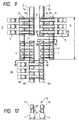
- Fig.10 shows a single connection diagram of a bus sectioning unit portion in a gas insulated switchgear device and Fig.11 shows the arrangement structure thereof.
- the entire length L' of the bus sectioning unit including a main bus potential transformer (PT) unit 16 reaches upto 27 m and further the area required therefor is great.
- PT main bus potential transformer
- An object of the present invention is to realize a compact unit by combining the main bus PT unit 16 and main bus sectioning units 3 and 4 and as well as to shorten the length of the main buses and branching buses therein and to improve the cost therefor.
- gas circuit breakers for the bus sectioning unit are disposed further outside of both main buses and auxiliary buses, one of branching buses led out from both poles of the gas circuit breaker is directly connected to the auxiliary bus via a disconnecting switch, the other branching bus extends upto the upper portion of the main bus passing over the auxiliary bus and is connected via a disconnecting switch and a connecting conductor to the main bus, and at the connecting conductor between the disconnecting switch and the main bus a potential transformer to be connected to the main bus and an earthing switch used for working on the main bus are disposed, further at another connecting conductor connecting the main bus and the auxiliary bus without routing a circuit breaker another potential transformer to be connected to the main bus and another earthing switch used for working on the main bus are likely disposed, thereby the arrangement structure of the gas insulated switchgear device including the above mentioned elements according to the present invention is confined in a length within about 13.5 m which is comparable to the entire length of the conventional bus sectioning units 3 and 4.
- the main bus PT S and the main bus earthing switches (ES S ) in the bus sectioning units 3 and 4 the conventional necessity of providing an installation space for the main bus PT S and the main bus ES S in the main bus arrangement is eliminated and thus space reduction of the entire arrangement structure of the gas insulated switchgear device is realized. Further, because of unnecessity of providing PT S for other feeder units and for main bus connecting units a standardization of the gas insulated switchgear device is realized and thus except for the disposition of the main bus PT S and the main bus ES S the main bus sectioning units 3 and 4 according to the present invention are constituted in the same arrangement structure as of a main bus connecting unit 14.
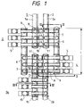
- Fig.1 is a plane view showing a main bus sectioning unit and the vicinity thereof for a double bus type gas insulated switchgear device of one embodiment according to the present invention, wherein vertical type circuit breakers are exemplarily used for the main bus sectioning use gas circuit breakers 5.
- Gas insulated main buses 1 and 2 are a linearly constituted three phase collective type and are disposed in an opposing manner on two parallel straight lines at substantially the same height level. Both the gas insulated main buses 1 and 2 are sectioned into two portions at the bus sectioning position, and gas insulated main bus sections 1a and 1b, and 2a and 2b are respectively to be connected by the main bus sectioning units 3 and 4.
- the main bus sectioning units 3 and 4 are primarily constituted by the gas circuit breakers 5, the gas insulated auxiliary buses 6 and gas insulated branching buses 7 or 9.
- the gas insulated auxiliary buses 6 are a three phase collective type and the others, for examples branching buses 7 and 9, are phase isolated type.
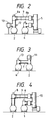
- Fig.2 is a diagram taken along the line II-II in Fig.1 and shows the construction structure relating primarily to the gas circuit breaker 5.
- the gas insulated main bus 2 and the gas insulated auxiliary bus 6 are disposed in parallel at a same height level, and further the gas circuit breaker 5 is disposed at the opposite side of the auxiliary bus 6 from the side where the main bus 2 is disposed.
- a vertical type circuit breaker is used for the gas circuit breaker 5 and the directions of two leading out conductors from the gas circuit breaker 5 toward the auxiliary bus 6 are substantially horizontal.
- the leading out portion from the lower portion of the circuit breaker 5 is connected to the auxiliary bus 6 via a disconnecting switch 8b which is disposed vertically above the auxiliary bus 6, on the other hand the leading out portion from the upper portion of the gas circuit breaker 5 extends above the auxiliary bus 6 by means of the branching bus 9 and is connected to the main bus 2 via a disconnecting switch 8a which is disposed vertically above the main bus 2.
- the disconnecting switch 8a disposed above the main bus 2 is not at the same height level as of the disconnecting switch 8b disposed above the auxiliary bus 6 but at a higher position in accordance with the height level of the branching bus 9. Further, at the branching bus portion between the disconnecting switch 8a and the main bus 2 a main bus connected PT 10 and a main bus use ES 12 are disposed.
- Fig.3 is a diagram taken along the line III-III in Fig.1 and shows an arrangement structure relating primarily to the gas insulated branching bus 7.
- the gas insulated main bus 2 and the gas insulated auxiliary bus 6 are respectively provided with an upwardly directing opening portion, and branching buses led out perpendicularly from the respective opening portions are connected by the horizontal branching bus 7. Further, at the midway of the branching bus 7 a main bus connected PT 11 and a main bus use ES 13 are provided.
- the main bus connection use PT S 10 and 11 and the main bus use ES S 12 and 13 can be concentratedly disposed in the bus sectioning units 3 and 4. Accordingly, the conventionally required space for the bus PT units 16 as shown in Fig.11 is eliminated, thereby the length in the main bus axial direction of the gas insulated switchgear device can be shortened.
- the arrangement structure including the circuit breakers 5 is formed substantially identical as that for the bus connecting units 14. Namely, when comparing Fig.2 which shows a side view of the bus sectioning unit 4 with Fig.4 which is a diagram taken along the line IV-IV in Fig.1 and shows a side view of the bus connecting unit 14, it is understood that the bus sectioning units 3 and 4 are constituted by adding a set of the PT 10 and the ES 12 to the bus connecting unit 14, thus the unit constitution thereof is simplified.
- bus sectioning units 3 and 4 are disposed at the outer sides of the respective belonging main buses while facing each other, however, the location of the branching bus 9 including the gas circuit breaker 5 and the branching bus 7 with no gas circuit breaker 5 in the bus sectioning unit 3 is inverted from that in the bus sectioning unit 4, namely the bus sectioning units 3 and 4 are disposed in rotation symmetry with respect to both the main buses. The importance thereof is explained hereinbelow.
- the main bus connected PT S 10 are disposed so as to project toward the space between the main buses 1 and 2 from the branching bus which is led out perpendicularly and upwardly from the respective main buses 1 and 2. Because of the disposition of the bus PT S 10 at the same height level as the facing main bus and of the rotation symmetry arrangement, the bus PT S 10 are arranged in the space between the main buses 1 and 2 in the axial direction thereof while displacing the locations thereof without enlarging the spacing distance between the main buses 1 and 2, as well as the height of the entire arrangement structure of the bus sectioning units can be also limited.
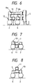
- the bus PT S 10 make use of gas insulated wound type transformers and are disposed in the space between the two main buses 1 and 2, and the main bus use ES S 12 are disposed at the same height level as the bus PT S 10 but at the opposite side with respect to the connecting conductor, however the arrangement structure with regard to their connecting position and direction is not limited to the present embodiment as will be understood from the following embodiments except that the bus PT 10 and the main bus use ES 12 are to be connected to the connecting conductor between the disconnecting switch 8a and the corresponding main bus. Accordingly, the positional relationship between the main bus connected PT 10 and the main bus use ES 12 as shown in Fig.2 can be inverted as shown in Fig.6.
- the arrangement structure of the main bus connected PT 11 and the main bus use ES 13 with regard to their connecting position and direction as shown in Fig.3 is not specifically limited thereto except that the main bus connected PT 11 and the main bus use ES 13 are to be connected to the branching bus 7. Therefore, the main bus connected PT 11 can be disposed so as to hang down from the branching bus 7 into the spade between the main bus 2 and the auxiliary bus 6 as shown in Fig.7, and contrary thereto the main bus connected PT 11 can be disposed so as to stand up on the branching bus 7 as shown in Fig.8.
- the arrangement structure as shown in Fig.7 improves the earth quake resistance because of the lowered center of gravity in comparison with those shown in Figs.3 and 8.
- Fig.5 is the entire arrangement structure of the bus sectioning units 3 and 4 when the main bus connected PT S 10 and 11 are disposed at the side of the auxiliary buses 6 other than the main buses 1 and 2 as shown in Figs.6, 7 and 8, and as will be seen from the arrangement structure as shown in Fig.5, the advantages of arranging the bus sectioning units 3 and 4 in rotation symmetry as has been explained above can not be any more enjoyed, therefore the respective bus sectioning units 3 and 4 can be constituted as shown in Fig.9. Namely, the bus sectioning units 3 and 4 for the respective main buses 1 and 2 are arranged substantially in line symmetry with regard to the axial direction of the main buses 1 and 2.
- main bus connected PT S and the main bus working use ES S are concentratedly arranged in the respective bus sectioning units for the gas insulated switchgear device and the arrangement structure for the respective bus sectioning units is optimized, thereby the entire arrangement structure of the gas insulated switchgear device can be rationalized and compacted as well as the length of the main buses and the branching buses is shortened which greatly improve the cost therefor.
Landscapes
- Engineering & Computer Science (AREA)
- Power Engineering (AREA)
- Gas-Insulated Switchgears (AREA)
- Driving Mechanisms And Operating Circuits Of Arc-Extinguishing High-Tension Switches (AREA)
Applications Claiming Priority (3)
| Application Number | Priority Date | Filing Date | Title |
|---|---|---|---|
| JP32662994 | 1994-12-28 | ||
| JP06326629A JP3136932B2 (ja) | 1994-12-28 | 1994-12-28 | ガス絶縁開閉装置 |
| JP326629/94 | 1994-12-28 |
Publications (3)
| Publication Number | Publication Date |
|---|---|
| EP0720263A2 true EP0720263A2 (de) | 1996-07-03 |
| EP0720263A3 EP0720263A3 (de) | 1996-12-27 |
| EP0720263B1 EP0720263B1 (de) | 1999-06-16 |
Family
ID=18189934
Family Applications (1)
| Application Number | Title | Priority Date | Filing Date |
|---|---|---|---|
| EP95119655A Expired - Lifetime EP0720263B1 (de) | 1994-12-28 | 1995-12-13 | Metallgekapselte gasisolierte Schaltvorrichtung |
Country Status (7)
| Country | Link |
|---|---|
| US (1) | US5757614A (de) |
| EP (1) | EP0720263B1 (de) |
| JP (1) | JP3136932B2 (de) |
| KR (1) | KR100382027B1 (de) |
| CN (1) | CN1047883C (de) |
| DE (1) | DE69510317T2 (de) |
| TW (1) | TW279282B (de) |
Families Citing this family (13)
| Publication number | Priority date | Publication date | Assignee | Title |
|---|---|---|---|---|
| JPH10229614A (ja) * | 1997-02-14 | 1998-08-25 | Hitachi Ltd | ガス絶縁開閉装置 |
| FR2761823B1 (fr) * | 1997-04-08 | 1999-05-14 | Gec Alsthom T & D Sa | Poste de distribution d'energie electrique |
| DE19805705A1 (de) * | 1998-02-06 | 1999-08-12 | Asea Brown Boveri | Gasisolierte metallgekapselte Schaltanlage |
| US6560091B1 (en) * | 1999-09-29 | 2003-05-06 | Hitachi, Ltd. | Gas insulated switchgear |
| US6556428B1 (en) | 2002-01-14 | 2003-04-29 | Hitachi, Ltd. | Gas insulated switchgear |
| JP4559887B2 (ja) * | 2005-03-22 | 2010-10-13 | 株式会社東芝 | ガス絶縁開閉装置 |
| US7414827B2 (en) * | 2005-12-27 | 2008-08-19 | Japan Ae Power Systems Corporation | Gas-insulated switchgear device |
| WO2008139592A1 (ja) * | 2007-05-11 | 2008-11-20 | Mitsubishi Electric Corporation | ガス絶縁開閉装置 |
| DE102007047200A1 (de) * | 2007-05-31 | 2008-12-04 | Abb Technology Ag | Hochspannungsschaltanlage |
| JP5875466B2 (ja) * | 2012-05-31 | 2016-03-02 | 株式会社日立製作所 | スイッチギヤまたはスイッチギヤの組立方法 |
| CN110707537B (zh) * | 2018-07-09 | 2021-09-07 | 河南平芝高压开关有限公司 | 一种包含z型转接段的gis设备 |
| CN110729635B (zh) * | 2018-07-17 | 2022-04-19 | 河南平芝高压开关有限公司 | 一种气体绝缘金属封闭开关设备 |
| KR102631016B1 (ko) | 2019-09-09 | 2024-01-31 | 한국전력공사 | 밸브 상태 표시 장치 및 이를 포함하는 가스절연개폐설비 |
Family Cites Families (12)
| Publication number | Priority date | Publication date | Assignee | Title |
|---|---|---|---|---|
| US4032820A (en) * | 1974-05-06 | 1977-06-28 | Hitachi, Ltd. | Horizontal double plane high voltage switching assembly |
| JPS5385353A (en) * | 1977-01-05 | 1978-07-27 | Hitachi Ltd | Compact-spaced switching device |
| EP0058402B1 (de) * | 1981-02-12 | 1984-12-19 | Kabushiki Kaisha Toshiba | Gasisolierte Schaltanlage |
| DE3506383A1 (de) * | 1985-02-23 | 1986-09-04 | Sachsenwerk, Licht- und Kraft-AG, 8000 München | Elektrische schaltanlagen und schaltverfahren dieser anlage |
| JPS62144506A (ja) * | 1985-12-17 | 1987-06-27 | 株式会社日立製作所 | ガス絶縁開閉装置 |
| KR960015127B1 (ko) * | 1986-10-07 | 1996-10-28 | 가부시기가이샤 히다찌 세이사꾸쇼 | 가스절연 개폐장치 |
| JPH0828925B2 (ja) * | 1988-03-11 | 1996-03-21 | 株式会社日立製作所 | ガス絶縁開閉装置 |
| JP2625512B2 (ja) * | 1988-08-03 | 1997-07-02 | 株式会社日立製作所 | ガス絶縁開閉装置 |
| JP2642477B2 (ja) * | 1989-04-14 | 1997-08-20 | 株式会社東芝 | ガス絶縁開閉装置 |
| JPH04299007A (ja) * | 1991-03-27 | 1992-10-22 | Toshiba Corp | ガス絶縁開閉装置 |
| JP2887857B2 (ja) * | 1992-08-07 | 1999-05-10 | 株式会社日立製作所 | ガス絶縁開閉装置 |
| JP3206305B2 (ja) * | 1994-07-05 | 2001-09-10 | 株式会社日立製作所 | ガス絶縁開閉装置 |
-
1994
- 1994-12-28 JP JP06326629A patent/JP3136932B2/ja not_active Expired - Fee Related
-
1995
- 1995-12-13 EP EP95119655A patent/EP0720263B1/de not_active Expired - Lifetime
- 1995-12-13 DE DE69510317T patent/DE69510317T2/de not_active Expired - Fee Related
- 1995-12-21 TW TW084113718A patent/TW279282B/zh active
- 1995-12-27 US US08/579,348 patent/US5757614A/en not_active Expired - Fee Related
- 1995-12-27 KR KR1019950058262A patent/KR100382027B1/ko not_active Expired - Fee Related
- 1995-12-28 CN CN95120197A patent/CN1047883C/zh not_active Expired - Fee Related
Also Published As
| Publication number | Publication date |
|---|---|
| EP0720263B1 (de) | 1999-06-16 |
| CN1047883C (zh) | 1999-12-29 |
| TW279282B (en) | 1996-06-21 |
| KR100382027B1 (ko) | 2003-07-12 |
| JPH08182128A (ja) | 1996-07-12 |
| CN1131835A (zh) | 1996-09-25 |
| KR960027116A (ko) | 1996-07-22 |
| DE69510317T2 (de) | 2000-02-24 |
| DE69510317D1 (de) | 1999-07-22 |
| EP0720263A3 (de) | 1996-12-27 |
| JP3136932B2 (ja) | 2001-02-19 |
| US5757614A (en) | 1998-05-26 |
Similar Documents
| Publication | Publication Date | Title |
|---|---|---|
| EP0720263A2 (de) | Metallgekapselte gasisolierte Schaltvorrichtung | |
| EP0156107A1 (de) | Gasisolierte Schaltanlage | |
| US6646861B1 (en) | Gas insulated switchgear | |
| EP0294766A2 (de) | Gasisolierte Schaltanlage | |
| US6664493B2 (en) | Gas-insulated switchgear | |
| CN101669260A (zh) | 气体绝缘开关装置 | |
| US5453910A (en) | Gas insulated switchgear device | |
| EP0058402B1 (de) | Gasisolierte Schaltanlage | |
| JPH0611163B2 (ja) | ガス絶縁開閉装置 | |
| JP2601238B2 (ja) | ガス絶縁開閉装置 | |
| JPS60183910A (ja) | ガス絶縁開閉装置 | |
| JPH076651Y2 (ja) | ガス絶縁開閉装置 | |
| JPH0152961B2 (de) | ||
| JPH07193925A (ja) | ガス絶縁開閉装置 | |
| JPH11146516A (ja) | ガス絶縁開閉装置 | |
| JPH06197421A (ja) | ガス絶縁開閉装置 | |
| JP2000134732A (ja) | ガス絶縁開閉装置 | |
| JPH0898344A (ja) | ガス絶縁開閉装置 | |
| JPS63194505A (ja) | ガス絶縁開閉装置 | |
| JPH09149514A (ja) | ガス絶縁開閉装置 | |
| JP2003111222A (ja) | ガス絶縁開閉装置 | |
| JPS61167307A (ja) | ガス絶縁開閉装置 | |
| JPS609401B2 (ja) | ガス絶縁開閉装置を用いた配電装置 | |
| JP2000125426A (ja) | ガス絶縁開閉装置 | |
| JPH1032905A (ja) | 集合形変電設備 |
Legal Events
| Date | Code | Title | Description |
|---|---|---|---|
| PUAI | Public reference made under article 153(3) epc to a published international application that has entered the european phase |
Free format text: ORIGINAL CODE: 0009012 |
|
| AK | Designated contracting states |
Kind code of ref document: A2 Designated state(s): CH DE LI |
|
| PUAL | Search report despatched |
Free format text: ORIGINAL CODE: 0009013 |
|
| AK | Designated contracting states |
Kind code of ref document: A3 Designated state(s): CH DE LI |
|
| 17P | Request for examination filed |
Effective date: 19970627 |
|
| 17Q | First examination report despatched |
Effective date: 19971017 |
|
| GRAG | Despatch of communication of intention to grant |
Free format text: ORIGINAL CODE: EPIDOS AGRA |
|
| GRAG | Despatch of communication of intention to grant |
Free format text: ORIGINAL CODE: EPIDOS AGRA |
|
| GRAG | Despatch of communication of intention to grant |
Free format text: ORIGINAL CODE: EPIDOS AGRA |
|
| GRAH | Despatch of communication of intention to grant a patent |
Free format text: ORIGINAL CODE: EPIDOS IGRA |
|
| GRAH | Despatch of communication of intention to grant a patent |
Free format text: ORIGINAL CODE: EPIDOS IGRA |
|
| GRAA | (expected) grant |
Free format text: ORIGINAL CODE: 0009210 |
|
| AK | Designated contracting states |
Kind code of ref document: B1 Designated state(s): CH DE LI |
|
| REG | Reference to a national code |
Ref country code: CH Ref legal event code: NV Representative=s name: TROESCH SCHEIDEGGER WERNER AG Ref country code: CH Ref legal event code: EP |
|
| REF | Corresponds to: |
Ref document number: 69510317 Country of ref document: DE Date of ref document: 19990722 |
|
| PLBE | No opposition filed within time limit |
Free format text: ORIGINAL CODE: 0009261 |
|
| STAA | Information on the status of an ep patent application or granted ep patent |
Free format text: STATUS: NO OPPOSITION FILED WITHIN TIME LIMIT |
|
| 26N | No opposition filed | ||
| PGFP | Annual fee paid to national office [announced via postgrant information from national office to epo] |
Ref country code: DE Payment date: 20020227 Year of fee payment: 7 |
|
| PGFP | Annual fee paid to national office [announced via postgrant information from national office to epo] |
Ref country code: CH Payment date: 20020305 Year of fee payment: 7 |
|
| PG25 | Lapsed in a contracting state [announced via postgrant information from national office to epo] |
Ref country code: LI Free format text: LAPSE BECAUSE OF NON-PAYMENT OF DUE FEES Effective date: 20021231 Ref country code: CH Free format text: LAPSE BECAUSE OF NON-PAYMENT OF DUE FEES Effective date: 20021231 |
|
| PG25 | Lapsed in a contracting state [announced via postgrant information from national office to epo] |
Ref country code: DE Free format text: LAPSE BECAUSE OF NON-PAYMENT OF DUE FEES Effective date: 20030701 |
|
| REG | Reference to a national code |
Ref country code: CH Ref legal event code: PL |