EP0717224B1 - Rohrhalter - Google Patents
Rohrhalter Download PDFInfo
- Publication number
- EP0717224B1 EP0717224B1 EP95810796A EP95810796A EP0717224B1 EP 0717224 B1 EP0717224 B1 EP 0717224B1 EP 95810796 A EP95810796 A EP 95810796A EP 95810796 A EP95810796 A EP 95810796A EP 0717224 B1 EP0717224 B1 EP 0717224B1
- Authority
- EP
- European Patent Office
- Prior art keywords
- jaws
- bent
- holding element
- pipe
- slot
- Prior art date
- Legal status (The legal status is an assumption and is not a legal conclusion. Google has not performed a legal analysis and makes no representation as to the accuracy of the status listed.)
- Expired - Lifetime
Links
- 239000002184 metal Substances 0.000 claims abstract description 21
- 238000000034 method Methods 0.000 claims description 20
- 238000005452 bending Methods 0.000 claims description 10
- 238000004519 manufacturing process Methods 0.000 claims description 9
- 230000000284 resting effect Effects 0.000 claims 2
- 238000004080 punching Methods 0.000 description 4
- 244000089486 Phragmites australis subsp australis Species 0.000 description 1
- ATJFFYVFTNAWJD-UHFFFAOYSA-N Tin Chemical compound [Sn] ATJFFYVFTNAWJD-UHFFFAOYSA-N 0.000 description 1
- 230000015572 biosynthetic process Effects 0.000 description 1
- 238000010276 construction Methods 0.000 description 1
- 238000005516 engineering process Methods 0.000 description 1
- 238000010438 heat treatment Methods 0.000 description 1
- 238000007373 indentation Methods 0.000 description 1
- 239000000463 material Substances 0.000 description 1
- 230000003278 mimic effect Effects 0.000 description 1
- 239000002023 wood Substances 0.000 description 1
Images
Classifications
-
- F—MECHANICAL ENGINEERING; LIGHTING; HEATING; WEAPONS; BLASTING
- F16—ENGINEERING ELEMENTS AND UNITS; GENERAL MEASURES FOR PRODUCING AND MAINTAINING EFFECTIVE FUNCTIONING OF MACHINES OR INSTALLATIONS; THERMAL INSULATION IN GENERAL
- F16L—PIPES; JOINTS OR FITTINGS FOR PIPES; SUPPORTS FOR PIPES, CABLES OR PROTECTIVE TUBING; MEANS FOR THERMAL INSULATION IN GENERAL
- F16L3/00—Supports for pipes, cables or protective tubing, e.g. hangers, holders, clamps, cleats, clips, brackets
- F16L3/08—Supports for pipes, cables or protective tubing, e.g. hangers, holders, clamps, cleats, clips, brackets substantially surrounding the pipe, cable or protective tubing
- F16L3/10—Supports for pipes, cables or protective tubing, e.g. hangers, holders, clamps, cleats, clips, brackets substantially surrounding the pipe, cable or protective tubing divided, i.e. with two members engaging the pipe, cable or protective tubing
- F16L3/1008—Supports for pipes, cables or protective tubing, e.g. hangers, holders, clamps, cleats, clips, brackets substantially surrounding the pipe, cable or protective tubing divided, i.e. with two members engaging the pipe, cable or protective tubing with two members engaging the pipe, cable or tubing, both being made of thin band material completely surrounding the pipe
Definitions
- the invention relates to a device according to the preamble of patent claim 1 and a method for its production according to the preamble of the claim 6.
- Pipe holders especially for roof drain pipes, are used, preferably in a vertical one Hold location on a house wall, with a pipe clamp firmly attached to the house wall is connected, while a second fold-out is arranged on the drain pipe to be able to insert and hold with the pipe clamp closed.
- a pipe holder is known in which the bent end regions the clamp jaws made of sheet metal strips are the two parts of a swivel hinge form.
- One end area has two side tabs, one circular cylindrical Enclosing cavity (hinge eyelet) are curved.
- the cavity axis forms the pivot axis.
- the other end area has a vertical punching through on both sides transverse piece for the expansion of the metal strip.
- the end range is T-shaped (squat T).
- the crosspiece is folded outwards. At With a closed pipe clamp, this cross piece runs through the central axis of the hinge eyelet forming cavity.
- the width of the crosspiece corresponds to a game tolerance the diameter of the hinge eyelet.
- the cross piece serves as the swivel hinge as a hinge pin.
- the pivot hinge in DE-U 94 03 136.3 is analogous described pipe clamp formed.
- This pipe clamp is only partially on the pipe jacket. To secure against slipping To hold the drain pipe in this clamp, as in the CH-A 250 452, in particular shown in FIG. 1, wedges between the inside of the clamp jaw and be inserted into the pipe jacket. Also elastic cuffs were made or the like.
- axle bolt is formed by deforming the end regions of the FR-A 2 420 279 teaches clamp jaws.
- the pipe wall points an opening through which a curved tab then grips, the bending radius of which is adapted to the outside diameter of the pipe. If the clamp jaws are fully opened, the jaws can be taken apart.
- An analogous training is described in CH-A 322 006.
- the CH-A 250 452 shows either pipe holder with clamp jaws, which can be separated hooking are connected to each other, or at the clamp jaw ends as a hinge have a hinge axis replica.
- the object of the invention is to produce an easy to manufacture and safe to open and close Pipe holder, the proper holding of the pipe in particular allows an observer to have an attractive appearance, as well as to create a process for its manufacture.
- the invention solves this problem with the features of claims 1 and 6 by accordingly strong bending of the counter part after Outside.
- the holder is in the closed state their cheeks completely except for the tiniest areas and full on the pipe jacket, which results in a perfect Hold gives.
- This rich concern doesn't just result in one excellent fixation but an appealing look for a viewer.
- the whole bracket just looks "good craftsmanship”. It is therefore used by the craftsman as appreciated by the customer.
- the invention also solves the problem in that no more trying to make a "popular" hinge to reproduce a hinge axis and these gripping eyelets. Although there is at least one in the invention Eyelet present. However, the eye wall now slides in one Slit in the end area of the other cheek. The invention dispenses with any mechanical element in the hinge, which mimic the mechanical axis function or would empathize. A mechanical axis in the the actual meaning is no longer there. Now that Slot is responsible for the pivoting process also snagging due to a non-existing plate-shaped "Bolt replacement" no longer take place.
- the pipe holder according to the invention is can be produced by a simple punching and bending process. Instead of punching can of course can also be cut out.
- the tube holder 1 shown in Figure 1 without a roof drain pipe 2 has a hinged pipe clamp 3 with two pivotally held by means of a pivoting hinge 5, semicircular bent from a sheet metal strip first and second pipe clamp jaws 7a and 7b, which front in its flange means of an annular screw 9 part 10a or 10b are held together or pulled.
- a fastening member 16 is pressed with a wood screw thread 17 for a wall attachment.
- the hinge 5 is formed only by punching out the end regions of the pipe clamp jaws 7a and 7b and subsequent bending work without adding any further components. It is 23 (crosspiece) of the second pipe clamp jaw 7b, which is completely enclosed laterally from the end portions 19a and 19b of the first pipe clamp jaw 7a formed of an end portion acting as a counter-holder. Different numbers of end areas can also be used compared to this example. However, the sum of the number of end areas of one jaw plus that of the other jaw must always be an odd number.
- the first and second end regions 19a, 19b and 23 which form the hinge 5 are inseparably connected to one another and cannot get caught even during the pivoting process.
- the first end regions 19a and 19b are each bent from a lateral tab 21a or 21b to form a cylinder which is open at the top and bottom.
- the cylinder cross-section is circular only in a rough approximation; the deviations from this are explained below.
- the two end parts 24a and 24b of the crosspiece 23 of a T-shaped end region engage, which is separated from the rest of the pipe clamp jaw 7a by an upper and lower slot 25a and 25b .
- the crosspiece 23 is bent outwards relative to the subsequent part of the clamp jaws by an angle ⁇ between 30 ° and 70 °, preferably by an angle ⁇ between 35 ° and 55 °, here by approximately 45 °.
- a tube 2 corresponding to its cross section can be held and clamped in an accurately fitting manner without an additional element that can be inserted between the inside of the clamp jaws and the tubular jacket 29 .
- the geometric longitudinal axis 26 of the interior spaces 22a and 22b runs approximately perpendicular to the longitudinal extension of the sheet metal strip 27a which later forms the pipe clamp jaw 7b .
- the two slots 25a and 25b are shown in FIGS . 1 and 2 .
- the two end regions 19a and 19b reach through these two slots 25a and 25b .
- the parts 24a and 24b of the cross piece 23 which are inserted in the end regions 19a and 19b form a counter-holding part in the pivot hinge 5 .
- the cross piece 23 or the cross pieces moves freely.
- the simple swivel hinge 5 is ready. There is no longer an actual hardware axis.
- the width d of the cross piece 23 is smaller by a first tolerance than the diameter of each interior 22a or 22b .
- the first tolerance is chosen such that the width d of the cross piece 23 is always substantially smaller than the diameter of the inner spaces 22a and 22b bent out of the tabs 21a and 21b .
- the width s of the slots 25a and 25b is slightly larger by a second tolerance than the sheet thickness of the sheet metal strip 27a which later forms the pipe clamp jaw 7a .
- the second tolerance must be carefully selected and tested, since it is responsible for guiding the pipe clamp jaw 7a on the walls of the end regions 19a and 19b at the pivot hinge 5 . If the slot width s is chosen too large, the two pipe clamp jaws 7a and 7b wobble . If it is chosen too small, there is a jamming and the two pipe clamp jaws 7a and 7b . They can then only be opened and closed with difficulty.
- the first tolerance is less critical. If the width b of the cross piece 23 is chosen too large, a perfect pivoting of the pipe clamp jaws 7a and 7b is not guaranteed.
- the width d can, however, be chosen to be as small as desired, and is only limited by the remaining material thickness, which constitutes the mechanical stability, since the cross piece 23 has to act as a counterpart and must not "tear".
- the second tolerance must not be too small is selected in relation to the sheet thickness.
- the good contact is also achieved by bending the cross piece 23 between 30 ° and 70 °, preferably between 35 ° and 55 °, in particular about 45 ° with respect to the inner wall of the remaining part of the pipe clamp adjoining it to the outside.
- the full seating of the inner sides of the clamp jaws 7a and 7b on the tubular jacket 29 is shown in the critical area of the pivot hinge 5 in FIG. 7 .
- two, preferably equally thick and equally wide, sheet metal strips 27a and 27b are assumed. These two sheet metal strips 27a and 27b result in the two pipe clamp jaws 7a and 7b after the bending process described here . As shown in FIG. 2 , one end of the sheet metal strip 27a is punched out in such a way that two lateral tabs 21a and 21b remain. Two lateral slots 25a and 25b , aligned with one another, are punched into one end of the second sheet metal strip 27b perpendicular to the longitudinal extension of the sheet metal strip 27b .
- the width s of the slits 25a and 25b is larger by a tolerance than the sheet thickness of the sheet metal strip 27a according to the above description regarding the second tolerance.
- the slot length is preferably a quarter of the sheet width.
- the T-shaped end region formed by the slots 25a and 25b as a cross piece 23 has an extension d in the longitudinal direction of the metal strip 27b , which is less than the tab length divided by the value ⁇ . That is, the diameter of the interiors 22a and 22b of the laterally bent tabs 21a and 21b should be larger than the extension d by a large tolerance.
- the cross piece 23 is bent upward at approximately 45 ° along a line 31 connecting the longitudinal sides of the slot and facing away from the cross piece 23 .
- the two tabs 21a and 21b are then bent up into a tight semicircle 35 with an approximately straight end piece 36 using a shaped piece 33 having a round indentation.
- the two pre-bent sheet metal strips 27a and 27b are plugged together, as outlined in FIG. 5 , ie the pre-bent tabs 21a and 21b are inserted through the two slots 25a and 25b .
- a pipe clamp jaw designated by 41a has a central tab 42 at its free end.
- the other pipe clamp jaw, here designated 41b has a slot 43 which is provided with a clearance tolerance for the width of the tab 42 .
- the slot 43 is arranged such that when the tab 42 is inserted, the two pipe clamp jaws 41a and 41b are aligned.
- the distance d of the slot 43 from the free end is smaller by a tolerance than the length 1 of the tab 42 divided by the value ⁇ . For the tolerance, the information given above applies to the embodiment shown in FIG .
- tabs and slots can also be used.
- the tabs are only to be formed parallel to each other in the extension of the longitudinal extension of the pipe clamp jaws and the slots to match the tabs.
- the swivel hinge described here is not only to be used for pipe holders for roof drain pipes 2; it can also be used for other areas of application. Hinges in connection with are particularly suitable parts bent from sheet metal, because here the Stamping work for the tabs and Slots can be made. Additional areas of application are z. B. the house technology (sanitary, heating pipe fixings, ...), construction engineering etc .; also can Hinges on tin boxes, as described above, be trained in this way.
Landscapes
- Engineering & Computer Science (AREA)
- General Engineering & Computer Science (AREA)
- Mechanical Engineering (AREA)
- Clamps And Clips (AREA)
- Supports For Pipes And Cables (AREA)
- Bending Of Plates, Rods, And Pipes (AREA)
Description
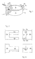
- Fig. 1
- einen Rohrhalter in perspektivischer Darstellung,
- Fig. 2
- eine Draufsicht auf die Endbereiche der beiden Rohrschellenbacken vor deren Biegen und der Formung des Rohrhalterscharniers,
- Fig. 3
- eine Seitenansicht des in einem ersten Verfahrensschritt aufgebogenen Endteils der einen Rohrschellenbacke,
- Fig. 4
- eine Seitenansicht des in einem weiteren Verfahrensschritt kreissegmentförmig gebogenen Endteils der anderen Rohrschellenbacke,
- Fig. 5
- eine Seitenansicht der beiden zusammengesteckten, gemäß Figur 3 und 4 gebogenen Endbereiche der beiden Rohrschellenbacken vor dem letzten Biegevorgang zur Scharnierbildung,
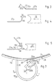
- Fig. 6
- eine Draufsicht analog zu Figur 2 auf eine Variante der Endbereiche und
- Fig. 7
- eine Draufsicht in vergrößerter Darstellung auf das Schwenkscharnier des Rohrhalters in der in Fig. 1 angedeuteten Blickrichtung VII, wobei hier der Rohrhalter um ein zu haltendes Rohr gelegt gezeigt ist, um sein sattes Aufliegen am Rohrmantel darzustellen.
Claims (8)
- Rohrhalter (1), insbesondere für die Halterung von Dachablaufrohren (2), mit zwei aus Blech gebogenen Schellenbacken (7a, 7b), deren benachbarte, untrennbar miteinander verbundene Endbereiche (19a, 19b, 23) ein angeformtes Schwenkschamier (5) bilden, wobei im ersten Endbereich (19a, 19b) der ersten Backe (7b) wenigstens eine Lasche (19, 19b) - einen Freiraum (22a, 22b) möglichst vollständig umschließend - umgebogen ist und im zweiten Endbereich der zweiten Backe wenigstens ein Gegenhalteteil (23) gegenüber dem anschließenden Schellenbackenrestteil nach außen um einen Winkel (α) zwischen 30° und 70°, bevorzugt um einen Winkel (α) zwischen 35° und 55° gebogen ist und dieser (23) durch wenigstens einen Schlitz (25a, 25b; 43) vom restlichen Backenteil abgesondert in jedem Freiraum (22a, 22b) liegt, dadurch gekennzeichnet, daß die Schlitzbreite (s) jedes den Gegenhalteteil (23) vom restlichen Backenteil absondernden Schlitzes (25a, 25b; 43) lediglich um eine geringfügige erste Toleranz größer ist als die Blechstärke der eingebogenen Lasche (21a, 21b) und die Breite (d) des Gegenhalteteils (23) immer wesentlich kleiner ist als der Durchmesser jedes Freiraums (22a, 22b), damit der Schwenkvorgang ohne Berührung der freien Stirnseite des Gegenhalteteils (23) bzw. der Gegenhalteteile (23) mit der eingebogenen Lascheninnenwandung und demzufolge nur durch Rutschen der Laschenwandung (21a, 21b) im Schlitz (25a, 25b; 43) erfolgt, d.h. das Schwenkscharnier (5) ist frei von jeglichem, eine mechanische Achsenfunktion nachempfindenden Element ausgebildet, wodurch im geschlossenen Zustand des Rohrhalters (1) ein dessen Querschnitt entsprechendes Rohr (2) paßgenau und insbesondere optisch ansprechend ohne zwischen der Schellenbackeninnenseite und dem Rohrmantel (29) einbringbarem Zusatzelement halterbar und einklemmbar ist.
- Rohrhalter (1) nach Anspruch 1, dadurch gekennzeichnet, daß die Abbiegung des Gegenhalteteils (23) an der dem Schellenbackenrestteil benachbarten Schlitzseite (31) beginnt.
- Rohrhalter (1) nach einem der Ansprüche 1 oder 2, dadurch gekennzeichnet, daß der Abbiegewinkel (α) und die Schlitzbreite (s) am Gegenhalteteil (23) derart gewählt sind, daß die anschließenden Backenrestteile im geschlossenen Zustand annähernd eine stetige Kurvenoberfläche bilden, damit ein sattes Anliegen an der Dachablaufrohrmantelfläche (29) möglich ist.
- Rohrhalter (1) nach einem der Ansprüche 1 bis 3, dadurch gekennzeichnet, daß der bzw. die Schlitze (25a, 25b) parallel zur geometrischen Scharnierachse (26) verläuft bzw. verlaufen.
- Rohrhalter (1) nach einem der Ansprüche 1 bis 4, dadurch gekennzeichnet, daß jeder Freiraum (22a, 22b) einen annähernd geraden Bodenbereich (38) hat, über dem jedes Laschenende geschlossen bis zur Auflage bzw. nahezu Auflage auf der Backenoberseite gebogen ist.
- Verfahren zur Herstellung des Rohrhalters (1) nach einem der Ansprüche 1 bis 5, wobei zur Herstellung des Schwenkscharniers (5) für die beiden Rohrschellenbacken (7a, 7b) wenigstens eine zur Backenlängsrichtung parallele Seiten aufweisende Lasche (21a, 21b) im Endbereich einer der beiden Backen (7a, 7b) herausgearbeitet wird, ein Gegenhalteteil (23) im Endbereich der anderen Backe (7a) durch Herausarbeiten wenigstens eines senkrecht zur Backenlängsrichtung verlaufenden Querschlitzes (25a, 25b) mit einer Schlitzbreite (s), welche lediglich um eine kleine Toleranz, insbesondere eine Spieltoleranz größer ist als die Blechstärke der Laschen, erzeugt wird, und der Querschlitz (25a, 25b) einen Abstand (d) vom benachbarten Rohrschellenbackenende hat, anschließend der Gegenhalteteil (23) nach außen um einen Winkel (α) zwischen 30° und 70°, bevorzugt um einem Winkel (α) zwischen 35° und 55° aufgebogen wird, und dann jede Lasche (21a, 21b) zu einer annähernd geschlossenen, auf der Backenoberseite aufliegenden Form derart um jeden Gegenhalteteil (23) aufgerollt wird, daß der Gegenhalteteil (23) mit den Laschen (21a, 21b) untrennbar verbunden ist und der die Breite des Gegenhalteteils (23) definierende Abstand (d) des Querschlitzes (25a, 25b) in Zusammenhang mit der Laschenlänge (I), welche den Durchmesser eines durch das Umbiegen der Laschen (21a, 21b) gebildeten Freiraums (22a, 22b) definiert, derart aufeinander abgestimmt werden, daß die Breite (d) des Gegenhalteteils (23) immer wesentlich kleiner ist als der Durchmesser jedes Freiraums (22a, 22b), um bei der Schwenkschamierbewegung nur ein Rutschen der Freiraumwand im Querschlitz (25a, 25b) ohne mechanische Achsenfunktion zu erhalten, was hier bei diesem bolzenfreien Scharnier einen verhakungsfreien Schwenkvorgang ermöglicht.
- Verfahren nach Anspruch 6, dadurch gekennzeichnet, daß jedes Laschenende beim Aufrollvorgang unter Vernachlässigung einer Kreiskontur derart gebogen wird, daß es annähernd senkrecht auf der Backenoberfläche aufsteht.
- Verfahren nach Anspruch 7, dadurch gekennzeichnet, daß das annähernd letzte Viertel (36) und insbesondere das erste Viertel (38) der gebogenen Laschenkontur unter Vernachlässigung einer annähernden Kreiskontur in einem angenähert geraden Verlauf gebogen wird bzw. werden.
Applications Claiming Priority (3)
| Application Number | Priority Date | Filing Date | Title |
|---|---|---|---|
| CH379894 | 1994-12-15 | ||
| CH3798/94 | 1994-12-15 | ||
| CH379894 | 1994-12-15 |
Publications (2)
| Publication Number | Publication Date |
|---|---|
| EP0717224A1 EP0717224A1 (de) | 1996-06-19 |
| EP0717224B1 true EP0717224B1 (de) | 2000-03-15 |
Family
ID=4263682
Family Applications (1)
| Application Number | Title | Priority Date | Filing Date |
|---|---|---|---|
| EP95810796A Expired - Lifetime EP0717224B1 (de) | 1994-12-15 | 1995-12-14 | Rohrhalter |
Country Status (3)
| Country | Link |
|---|---|
| EP (1) | EP0717224B1 (de) |
| AT (1) | ATE190706T1 (de) |
| DE (1) | DE59508001D1 (de) |
Families Citing this family (1)
| Publication number | Priority date | Publication date | Assignee | Title |
|---|---|---|---|---|
| GB2324568A (en) * | 1997-04-25 | 1998-10-28 | Walkern Victoria Ind Ltd | Clamps |
Family Cites Families (5)
| Publication number | Priority date | Publication date | Assignee | Title |
|---|---|---|---|---|
| CH250452A (de) * | 1945-03-12 | 1947-08-31 | Groelly H Peter | Rohrschelle. |
| DE7807698U1 (de) * | 1978-03-14 | 1978-06-22 | Steeb, Dieter, Steinegg-Appenzell (Schweiz) | Rohrschelle |
| DE3533951A1 (de) * | 1985-09-24 | 1987-04-02 | Heinz Dipl Ing Bosse | Rohrschelle, insbesondere zum verankern von regenfallrohren |
| DE9109365U1 (de) * | 1991-07-29 | 1991-11-28 | BEBEG Badische Eisen- und Blechwarenfabrik GmbH, 6920 Sinsheim | Rohrschelle |
| DE9403136U1 (de) * | 1994-02-25 | 1994-04-21 | Wilhelm Jöcker GmbH & Co. KG, 42349 Wuppertal | Schnapprohrschelle |
-
1995
- 1995-12-14 DE DE59508001T patent/DE59508001D1/de not_active Expired - Fee Related
- 1995-12-14 EP EP95810796A patent/EP0717224B1/de not_active Expired - Lifetime
- 1995-12-14 AT AT95810796T patent/ATE190706T1/de not_active IP Right Cessation
Also Published As
| Publication number | Publication date |
|---|---|
| EP0717224A1 (de) | 1996-06-19 |
| DE59508001D1 (de) | 2000-04-20 |
| ATE190706T1 (de) | 2000-04-15 |
Similar Documents
| Publication | Publication Date | Title |
|---|---|---|
| DE1772647B1 (de) | Verbindungsstueck von Glasteilen im Luesterbehang | |
| DE19630148A1 (de) | Türrahmen und Verfahren zum Bilden desselben | |
| DE2419183A1 (de) | Verfahren zum herstellen und zusammensetzen eines luftkastens mit rueckschlagklappe | |
| EP0717224B1 (de) | Rohrhalter | |
| WO2016100992A1 (de) | Verfahren zum verbinden von möbelbeschlagsteilen und möbelbeschlag | |
| DE3047820C2 (de) | Verfahren zur Herstellung eines Sicherungselementes zum axialen Festlegen von Bolzen, Wellen oder dergleichen | |
| DE29519000U1 (de) | Befestigungsbügel | |
| DE29619144U1 (de) | Trägerklammer | |
| DE2548853B2 (de) | Vorrichtung zur Herstellung von metallenen Ringrohlingen | |
| DE3602658A1 (de) | Rinnenstutzen | |
| CH542973A (de) | Metallgerüst aus Gerüstrohren, mit einem Aussteifungselement, und Verfahren zu dessen Herstellung | |
| DE3875244T2 (de) | Tuerrahmen und verfahren zur herstellung und montage desselben. | |
| DE102009040131B3 (de) | Befestigungslasche für ein Schutzzaunfeld | |
| DE69204379T2 (de) | Schubladenführungen und Verfahren zur Herstellung. | |
| DE2029843C3 (de) | Möbelscharnier | |
| DE650499C (de) | Werkzeugsatz zur handwerksmaessigen Herstellung von Dachrinnen | |
| DE2006109A1 (de) | Vorrichtung zum Biegen von Metallrohren | |
| DE10052252A1 (de) | Bordstück für Fensterbänke | |
| EP1051929B1 (de) | Verbesserte Verbindungseinrichtung für Schubladenfronten von Möbelschubladen | |
| DE2321047C3 (de) | Halterungsböckchen und Verfahren zu dessen Anbringung an einem schwenkbaren | |
| EP4261446A1 (de) | Befestigungsvorrichtung, anordnung mit einer befestigungsvorrichtung und verfahren zum herstellen einer befestigungsvorrichtung | |
| DE2556401C3 (de) | Behälter zur Kompostgewinnung | |
| DE3638994C2 (de) | Möbelscharnier | |
| DE102023105246A1 (de) | Regaleinschub | |
| DE546742C (de) | Vorrichtung zur Herstellung konischer Rohre |
Legal Events
| Date | Code | Title | Description |
|---|---|---|---|
| PUAI | Public reference made under article 153(3) epc to a published international application that has entered the european phase |
Free format text: ORIGINAL CODE: 0009012 |
|
| AK | Designated contracting states |
Kind code of ref document: A1 Designated state(s): AT CH DE FR IT LI |
|
| 17P | Request for examination filed |
Effective date: 19961125 |
|
| 17Q | First examination report despatched |
Effective date: 19981111 |
|
| GRAG | Despatch of communication of intention to grant |
Free format text: ORIGINAL CODE: EPIDOS AGRA |
|
| GRAG | Despatch of communication of intention to grant |
Free format text: ORIGINAL CODE: EPIDOS AGRA |
|
| GRAH | Despatch of communication of intention to grant a patent |
Free format text: ORIGINAL CODE: EPIDOS IGRA |
|
| GRAH | Despatch of communication of intention to grant a patent |
Free format text: ORIGINAL CODE: EPIDOS IGRA |
|
| GRAA | (expected) grant |
Free format text: ORIGINAL CODE: 0009210 |
|
| AK | Designated contracting states |
Kind code of ref document: B1 Designated state(s): AT CH DE FR IT LI |
|
| REF | Corresponds to: |
Ref document number: 190706 Country of ref document: AT Date of ref document: 20000415 Kind code of ref document: T |
|
| REG | Reference to a national code |
Ref country code: CH Ref legal event code: EP |
|
| ITF | It: translation for a ep patent filed | ||
| REG | Reference to a national code |
Ref country code: CH Ref legal event code: NV Representative=s name: KELLER & PARTNER PATENTANWAELTE AG |
|
| REF | Corresponds to: |
Ref document number: 59508001 Country of ref document: DE Date of ref document: 20000420 |
|
| ET | Fr: translation filed | ||
| PLBE | No opposition filed within time limit |
Free format text: ORIGINAL CODE: 0009261 |
|
| STAA | Information on the status of an ep patent application or granted ep patent |
Free format text: STATUS: NO OPPOSITION FILED WITHIN TIME LIMIT |
|
| 26N | No opposition filed | ||
| PGFP | Annual fee paid to national office [announced via postgrant information from national office to epo] |
Ref country code: AT Payment date: 20081218 Year of fee payment: 14 |
|
| PGFP | Annual fee paid to national office [announced via postgrant information from national office to epo] |
Ref country code: FR Payment date: 20081127 Year of fee payment: 14 |
|
| PGFP | Annual fee paid to national office [announced via postgrant information from national office to epo] |
Ref country code: DE Payment date: 20090224 Year of fee payment: 14 |
|
| PG25 | Lapsed in a contracting state [announced via postgrant information from national office to epo] |
Ref country code: IT Free format text: LAPSE BECAUSE OF NON-PAYMENT OF DUE FEES Effective date: 20071214 |
|
| PG25 | Lapsed in a contracting state [announced via postgrant information from national office to epo] |
Ref country code: AT Free format text: LAPSE BECAUSE OF NON-PAYMENT OF DUE FEES Effective date: 20091214 |
|
| REG | Reference to a national code |
Ref country code: FR Ref legal event code: ST Effective date: 20100831 |
|
| PG25 | Lapsed in a contracting state [announced via postgrant information from national office to epo] |
Ref country code: FR Free format text: LAPSE BECAUSE OF NON-PAYMENT OF DUE FEES Effective date: 20091231 |
|
| PG25 | Lapsed in a contracting state [announced via postgrant information from national office to epo] |
Ref country code: DE Free format text: LAPSE BECAUSE OF NON-PAYMENT OF DUE FEES Effective date: 20100701 |
|
| PGFP | Annual fee paid to national office [announced via postgrant information from national office to epo] |
Ref country code: IT Payment date: 20081222 Year of fee payment: 14 |
|
| PGRI | Patent reinstated in contracting state [announced from national office to epo] |
Ref country code: IT Effective date: 20110616 |
|
| PGRI | Patent reinstated in contracting state [announced from national office to epo] |
Ref country code: IT Effective date: 20110616 |
|
| PGFP | Annual fee paid to national office [announced via postgrant information from national office to epo] |
Ref country code: CH Payment date: 20141119 Year of fee payment: 20 |
|
| REG | Reference to a national code |
Ref country code: CH Ref legal event code: PCAR Free format text: NEW ADDRESS: EIGERSTRASSE 2 POSTFACH, 3000 BERN 14 (CH) |
|
| REG | Reference to a national code |
Ref country code: CH Ref legal event code: PL |