EP0716803B1 - Bauteil zur Herstellung von Beeteinfassungen und Abgrenzungen in Gärten und Grünanlagen - Google Patents
Bauteil zur Herstellung von Beeteinfassungen und Abgrenzungen in Gärten und Grünanlagen Download PDFInfo
- Publication number
- EP0716803B1 EP0716803B1 EP95119774A EP95119774A EP0716803B1 EP 0716803 B1 EP0716803 B1 EP 0716803B1 EP 95119774 A EP95119774 A EP 95119774A EP 95119774 A EP95119774 A EP 95119774A EP 0716803 B1 EP0716803 B1 EP 0716803B1
- Authority
- EP
- European Patent Office
- Prior art keywords
- building element
- building
- element according
- eyelet
- stud
- Prior art date
- Legal status (The legal status is an assumption and is not a legal conclusion. Google has not performed a legal analysis and makes no representation as to the accuracy of the status listed.)
- Expired - Lifetime
Links
- 229920003023 plastic Polymers 0.000 claims abstract description 6
- 239000004033 plastic Substances 0.000 claims abstract description 6
- 238000010413 gardening Methods 0.000 claims 1
- 230000000149 penetrating effect Effects 0.000 claims 1
- 239000002689 soil Substances 0.000 abstract description 2
- 238000013459 approach Methods 0.000 description 9
- 241000237858 Gastropoda Species 0.000 description 3
- 238000004519 manufacturing process Methods 0.000 description 3
- 230000008878 coupling Effects 0.000 description 2
- 238000010168 coupling process Methods 0.000 description 2
- 238000005859 coupling reaction Methods 0.000 description 2
- 229910052782 aluminium Inorganic materials 0.000 description 1
- XAGFODPZIPBFFR-UHFFFAOYSA-N aluminium Chemical compound [Al] XAGFODPZIPBFFR-UHFFFAOYSA-N 0.000 description 1
- 230000004888 barrier function Effects 0.000 description 1
- 239000011888 foil Substances 0.000 description 1
- 238000003780 insertion Methods 0.000 description 1
- 230000037431 insertion Effects 0.000 description 1
- 238000010409 ironing Methods 0.000 description 1
- 229910052751 metal Inorganic materials 0.000 description 1
- 239000002184 metal Substances 0.000 description 1
- 238000000465 moulding Methods 0.000 description 1
- 239000002574 poison Substances 0.000 description 1
- 231100000614 poison Toxicity 0.000 description 1
- 230000003014 reinforcing effect Effects 0.000 description 1
- 230000002940 repellent Effects 0.000 description 1
- 239000005871 repellent Substances 0.000 description 1
- 239000003351 stiffener Substances 0.000 description 1
Images

Classifications
-
- A—HUMAN NECESSITIES
- A01—AGRICULTURE; FORESTRY; ANIMAL HUSBANDRY; HUNTING; TRAPPING; FISHING
- A01G—HORTICULTURE; CULTIVATION OF VEGETABLES, FLOWERS, RICE, FRUIT, VINES, HOPS OR SEAWEED; FORESTRY; WATERING
- A01G9/00—Cultivation in receptacles, forcing-frames or greenhouses; Edging for beds, lawn or the like
- A01G9/28—Raised beds; Planting beds; Edging elements for beds, lawn or the like, e.g. tiles
Definitions
- the invention relates to a component for the production of Bed borders and demarcations from several corresponding components, the respective component for releasable connection of corresponding components on the an eyelet and on the lower half of one end an upper half of the other face partially cylindrical, provided with a recess having.
- Such a component is from FR 2 661 461 A1 and U.S.-A-4,869,018.
- DE 91 12 998 U1 discloses a molded part that especially for erecting a boundary wall for a sandpit is determined and a wall section with has two vertical end edge regions on which in the height offset from each other Connection section with a vertical hole like this is set that the holes of an upper Connection section and a lower Connecting section of adjacent moldings in alignment bring and to each other through a separate connector are connecting.
- a disadvantage of this prior art is that for Connection of two components always additional Coupling parts are required, which the Increase production costs and assembly costs.
- US 5,119,587 relates to border elements Convex / concave design of the end faces, resulting in a certain fixation of horizontally adjacent components is achieved. These elements can be used for connection horizontally adjacent elements on one side Pen and on the other side a recess for Recording the pen of a horizontally adjacent one Elements have. But such an element is not for connection to another vertically arranged Element suitable.
- the object of the invention is therefore, the components to provide the type mentioned at the beginning, which none make additional coupling parts necessary.
- this object is achieved by a Component for the production of bed borders and Boundaries in gardens and green areas from several corresponding components, the respective component for releasable connection of corresponding components on the lower half of a face a partially cylindrical eyelet and one on the top half of the other end corresponding part-cylindrical, with a recess provided approach, which depends on the approach the lower side opposite the recess a pin connects, which together with the eyelet of a neighboring component in the horizontal direction is designed to connect the two components, with the eyelet, the neck and the pin all Are components of the component, and the Recess and the pin are designed so that if two components are placed vertically on top of each other, the lower part of the pin of the upper component in the Recess of the component located below.
- the component can have any practical dimensions, based on the intended use and the nature of the soil can be coordinated. It is also possible to have several To put components on top of each other. At this Embodiment, the lower part of the pin sits in the recess of the component underneath.
- the Components according to the invention can thus also in height can be combined in a stable manner.
- a generally applicable size is about a length 60 cm, a width of about 5 cm and a height of about 13 to 15 cm.
- the component is from a suitable one Plastic, preferably recycled plastic, but could also consist of metal such as aluminum.
- the component is in use with an open one Pushed down into the ground for what purpose the edges of the flanges of the U-profile and the free edge of the transverse walls tapered like a cutting edge (i.e. chamfered) are.
- the pin of the partially cylindrical approach through the eyelet and preferably also penetrates a corresponding piece the earth.
- the part-cylindrical approach is then on the eyelet, which is also partially cylindrical and complements this to the full profile height, so that the components plugged together to form a complete strand result in the same amount of delimitation.
- the holes of the eyelets with springs or Grooves can be provided with corresponding grooves or Coil springs on the pin so that positive connections result.
- the holes or Recesses of the part-cylindrical approaches, which the Wear pens, and if necessary those of the pens, also serve to hold pipe brackets for tunnel foils or that of multipurpose poles or Multi-purpose ironing.
- pockets in the profile be included in the supports, rods and slats for Garden plants are insertable. Become the recesses or holes in the lugs are not required, you can use be closed with a cap.
- the edge of the profile with a Cantilever provided as a snail barrier, the molded at right angles and protruding and on Snail repellent among themselves, which then is protected against rain at the same time.
- This The anti-snail edge is designed so that the ends the overhanging edge when the elements are put together fit one above the other in a straight extension. This will thereby allowing the edges to be slightly offset are molded. It extends up to an angle of 33 ° Length of the molded edge to reduce the angle conclude. At an angle of 90 ° the resulting Interruption at the edge of the snail by a Additional part bridged, the one after the other end the cantilever can be inserted.
- the overhang can serve as a lawn edge, in which case it rests on the floor. she serves as a running track for the wheels of the lawnmower and ensures one clean cut of the lawn.
- the component described above is an elongated, straight component described and in the drawing shown. But it can be done with the same Features according to the invention are also curved, i.e. be arched, for example such that 20 arc-shaped components give a full circle to one Border of flowers.
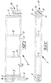
- the main part of the component comprises a U-shaped profile 1 made of plastic, which in its interior transverse walls 2 for Contains stiffening.
- the ends of the profile 1 are through End walls 3 completed.
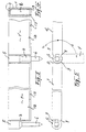
- Each end wall 3 carries one partially cylindrical approach 4 and 5, of which one Approach 4 formed on the lower half of the end wall 3 while the other approach 5 is on the top half of the other end wall is molded.
- the upper shoulder 5 is down through a pin 6 lengthened when two components are plugged together through the bore 7 of the lower one forming an eyelet 11 Approach reaches through and a desired piece penetrates into the ground.
- hole 7 and pin 6 can be used Profiles such as tongue and groove should be provided so that there is a positive connection, as in FIG. 2 indicated at 10 in the bore 7 of the eyelet 11.
- Edges 12 beveled or chamfered as shown at 13.
- the side of the component is with Cantilever 14.15 at the connection point to the next Component shown.
- the cantilevered, right angle integrally formed edge 14, 15 offset so that the Connection of two components when plugging the canting edges fit over one another.
- the Cantilever 14 can be seen on the side of the component in this Case with a reinforcing rib 16 which is fixed to the Cantilever is connected, is molded.
Landscapes
- Life Sciences & Earth Sciences (AREA)
- Environmental Sciences (AREA)
- Soil Working Implements (AREA)
- Bedding Items (AREA)
- Cultivation Of Plants (AREA)
- Road Paving Structures (AREA)
- Cultivation Receptacles Or Flower-Pots, Or Pots For Seedlings (AREA)
Description
- Fig. 1
- eine Seitenansicht des erfindungsgemäßen Bauteils,
- Fig. 2
- eine Draufsicht,
- Fig. 3
- eine abgewandelte Ausführungsform,
- Fig. 4
- einen Querschnitt,
- Fig. 5
- eine Draufsicht zweier zusammengesteckter Bauteile in ihrer Verschwenkbarkeit,
- Fig. 6
- seine Seitenansicht am Ende des Bauteils und
- Fig. 7
- eine Aufsicht auf die Stirnseite am Ende des Bauteils.
Claims (9)
- Bauteil zur Herstellung von Beeteinfassungen und Abgrenzungen in Gärten und Grünanlagen aus mehreren entsprechenden Bauteilen, wobei das jeweilige Bauteil (1, 1') zur lösbaren Verbindung entsprechender Bauteile (1, 1') an der unteren Hälfte einer Stirnseite (3) eine teilzylindrische Öse (11) und an der oberen Hälfte der anderen Stirnseite einen entsprechenden teilzylindrischen, mit einer Ausnehmung (8) versehenen Ansatz (5) aufweist, wobei sich an den Ansatz (5) an der unteren der Ausnehmung gegenüberliegenden Seite ein Stift (6) anschließt, der zusammen mit der Öse (11) eines in horizontaler Richtung benachbarten Bauteils zum Verbinden der beiden Bauteile (1,1') ausgebildet ist, und wobei die Öse, der Ansatz und der Stift alle Bestandteile des Bauteils sind,
dadurch gekennzeichnet,
daß die Ausnehmung (8) und der Stift (6) so ausgebildet sind, daß wenn zwei Bauteile (1,1') vertikal aufeinander gesetzt werden, der untere Teil des Stifts des oberen Bauteils in der Ausnehmung des darunter befindlichen Bauteils sitzt. - Bauteil nach Anspruch 1, dadurch gekennzeichnet, daß es in Form eines U-Profils ausgestaltet ist.
- Bauteil nach einem der vorhergehenden Ansprüche, dadurch gekennzeichnet, daß das Bauteil (1, 1') gerade oder bogenförmig ausgebildet ist.
- Bauteil nach einem der vorhergehenden Ansprüche, dadurch gekennzeichnet, daß die in das Erdreich eindringenden Ränder (12) des U-Profils abgeschrägt sind.
- Bauteil nach einem der vorhergehenden Ansprüche, dadurch gekennzeichnet, daß das U-Profil des Bauteils (1, 1') im Inneren Querwände (2) aufweist.
- Bauteil nach einem der vorhergehenden Ansprüche, dadurch gekennzeichnet, daß die Bohrung (7) in der Öse (11) als auch der Stift (6) Profilierungen (10) zur formschlüssigen Verbindung zweier Bauteile (1, 1') aufweisen.
- Bauteil nach einem der vorhergehenden Ansprüche, dadurch gekennzeichnet, daß seitlich längs des Bauteils eine Auskragung angeformt ist.
- Bauteil nach einem der vorhergehenden Ansprüche, dadurch gekennzeichnet, daß die Enden (9) der Bauteile (1) an der Verbindungsstelle zum Ansatz (5) abgeschrägt sind.
- Bauteil nach einem der vorhergehenden Ansprüche, dadurch gekennzeichnet, daß es aus Kunststoff, vorzugsweise Recycling-Kunststoff, besteht.
Applications Claiming Priority (2)
| Application Number | Priority Date | Filing Date | Title |
|---|---|---|---|
| DE9420128U | 1994-12-16 | ||
| DE9420128U DE9420128U1 (de) | 1994-12-16 | 1994-12-16 | Bauteil zur Herstellung von Beeteinfassungen und Abgrenzungen in Gärten und Grünanlagen |
Publications (2)
| Publication Number | Publication Date |
|---|---|
| EP0716803A1 EP0716803A1 (de) | 1996-06-19 |
| EP0716803B1 true EP0716803B1 (de) | 2000-06-07 |
Family
ID=6917484
Family Applications (1)
| Application Number | Title | Priority Date | Filing Date |
|---|---|---|---|
| EP95119774A Expired - Lifetime EP0716803B1 (de) | 1994-12-16 | 1995-12-15 | Bauteil zur Herstellung von Beeteinfassungen und Abgrenzungen in Gärten und Grünanlagen |
Country Status (4)
| Country | Link |
|---|---|
| EP (1) | EP0716803B1 (de) |
| AT (1) | ATE193634T1 (de) |
| DE (2) | DE9420128U1 (de) |
| DK (1) | DK0716803T3 (de) |
Cited By (2)
| Publication number | Priority date | Publication date | Assignee | Title |
|---|---|---|---|---|
| WO2012118443A1 (en) * | 2011-03-03 | 2012-09-07 | Housing And Development Board | A modular and customisable planting system |
| RU194716U1 (ru) * | 2019-04-15 | 2019-12-19 | Олеся Александровна Юнусова | Модульный элемент бордюра |
Families Citing this family (13)
| Publication number | Priority date | Publication date | Assignee | Title |
|---|---|---|---|---|
| DE9420128U1 (de) * | 1994-12-16 | 1995-02-09 | W. Neudorff Gmbh Kg, 31860 Emmerthal | Bauteil zur Herstellung von Beeteinfassungen und Abgrenzungen in Gärten und Grünanlagen |
| DE19730304A1 (de) * | 1997-07-15 | 1999-01-21 | Montagebau Maria Fuhrmann | Umrahmung für Beete |
| AT409701B (de) * | 1998-03-06 | 2002-10-25 | Wuester Heinrich | Mehrteilige begrenzungsmauer, insbesondere für frühbeete, sowie frühbeet |
| AT406928B (de) | 1998-08-28 | 2000-10-25 | Wuester Heinrich | Begrenzungsmauer, insbesonders für beeteinfassungen, frühbeete, abgrenzungen in garten- und grünanlagen oder dergleichen |
| US6202367B1 (en) * | 1999-01-14 | 2001-03-20 | Vegherb, Llc | Raised border system |
| EP1252815A3 (de) * | 2001-04-26 | 2003-06-11 | Hermann Dr. Keck | Vorrichtung zum Schutz von Pflanzen vor Schneckenfrass |
| GB2376261B (en) * | 2001-06-06 | 2004-05-19 | Stephen Paul King | Level edging kit |
| US6779297B2 (en) * | 2001-08-03 | 2004-08-24 | Easy Gardener Products, Ltd. | Lawn edging strip with improved end connectors |
| DE20202732U1 (de) * | 2002-02-21 | 2003-07-03 | Marley Deutschland GmbH, 31515 Wunstorf | Kantenstein, insbesondere für Rasen- oder Beet-Einfassungen |
| AU2003218996A1 (en) | 2002-02-21 | 2003-09-09 | Marley Deutschland Gmbh | Modular element for forming lawn or flowerbed borders or the like |
| DE102010036579A1 (de) * | 2010-07-23 | 2012-01-26 | Thomas Merschmann | Einfassungselement |
| FR3009922B1 (fr) * | 2013-09-05 | 2016-04-29 | Coppac | Systeme modulaire pour la realisation de bordure de jardin |
| RU2720692C1 (ru) * | 2019-09-16 | 2020-05-12 | Олеся Александровна Юнусова | Бордюр |
Citations (1)
| Publication number | Priority date | Publication date | Assignee | Title |
|---|---|---|---|---|
| US4869018A (en) * | 1987-04-13 | 1989-09-26 | Hjs Enterprises, Inc. | System forming a self-irrigating, raised bed |
Family Cites Families (13)
| Publication number | Priority date | Publication date | Assignee | Title |
|---|---|---|---|---|
| GB609905A (en) * | 1946-03-25 | 1948-10-08 | John Patrick Mcdermott | Improvements in and relating to garden edging |
| US3415013A (en) | 1966-11-02 | 1968-12-10 | Donald D. Galbraith | Interlocking-type border building unit |
| DE2841794A1 (de) * | 1978-09-26 | 1980-04-03 | Barth Gmbh Dr | Betonbauelement in form einer platte |
| DE2945292A1 (de) * | 1979-11-09 | 1981-05-21 | Heleon Herbert Hess KG, 7250 Leonberg | Kunststoffbegrenzungselement |
| DE3023309A1 (de) * | 1980-06-21 | 1982-01-07 | Franz Georg 7250 Leonberg fr.Höfingen eingem. Miller | Profil zur abgrenzung einer garten-oder beetflaeche |
| DE8427662U1 (de) * | 1984-09-20 | 1984-12-13 | Erich Schumm Gmbh, 7157 Murrhardt | Beet-einfassung |
| US5119587A (en) * | 1990-01-02 | 1992-06-09 | Waltz Ross E | Method and apparatus for landscape edging |
| FR2661461B1 (fr) * | 1990-04-26 | 1992-08-14 | Descamps Jean | Systeme d'articulation pour assembler et fixer des elements verticaux. |
| DE9112998U1 (de) * | 1991-10-18 | 1991-12-19 | Gummiwerk Kraiburg Elastik Beteiligungs-GmbH & Co, 8261 Tittmoning | Formteil, insbesondere als Begrenzungswand für einen Sandkasten |
| US5259154A (en) * | 1992-02-14 | 1993-11-09 | Lilley Eugene H | Landscape border |
| DE9211620U1 (de) * | 1992-08-28 | 1992-11-05 | Erich Schumm GmbH + Co. KG, 7157 Murrhardt | Einfassung für Gartenbeete o.dgl. |
| DE9216128U1 (de) * | 1992-11-29 | 1993-02-25 | Hausmann, Hermann, 7941 Unlingen | Universal-Rasenkanten-Einfassungselement |
| DE9420128U1 (de) * | 1994-12-16 | 1995-02-09 | W. Neudorff Gmbh Kg, 31860 Emmerthal | Bauteil zur Herstellung von Beeteinfassungen und Abgrenzungen in Gärten und Grünanlagen |
-
1994
- 1994-12-16 DE DE9420128U patent/DE9420128U1/de not_active Expired - Lifetime
-
1995
- 1995-12-15 AT AT95119774T patent/ATE193634T1/de not_active IP Right Cessation
- 1995-12-15 EP EP95119774A patent/EP0716803B1/de not_active Expired - Lifetime
- 1995-12-15 DE DE59508453T patent/DE59508453D1/de not_active Expired - Fee Related
- 1995-12-15 DK DK95119774T patent/DK0716803T3/da active
Patent Citations (1)
| Publication number | Priority date | Publication date | Assignee | Title |
|---|---|---|---|---|
| US4869018A (en) * | 1987-04-13 | 1989-09-26 | Hjs Enterprises, Inc. | System forming a self-irrigating, raised bed |
Cited By (3)
| Publication number | Priority date | Publication date | Assignee | Title |
|---|---|---|---|---|
| WO2012118443A1 (en) * | 2011-03-03 | 2012-09-07 | Housing And Development Board | A modular and customisable planting system |
| CN103533825A (zh) * | 2011-03-03 | 2014-01-22 | 建屋发展局 | 模块化可定制型种植系统 |
| RU194716U1 (ru) * | 2019-04-15 | 2019-12-19 | Олеся Александровна Юнусова | Модульный элемент бордюра |
Also Published As
| Publication number | Publication date |
|---|---|
| DE59508453D1 (de) | 2000-07-13 |
| ATE193634T1 (de) | 2000-06-15 |
| DK0716803T3 (da) | 2000-10-09 |
| DE9420128U1 (de) | 1995-02-09 |
| EP0716803A1 (de) | 1996-06-19 |
Similar Documents
| Publication | Publication Date | Title |
|---|---|---|
| DE60129182T2 (de) | Modularer Zaun | |
| DE1900397A1 (de) | Baustein | |
| EP0716803A1 (de) | Bauteil zur Herstellung von Beeteinfassungen und Abgrenzungen in Gärten und Grünanlagen | |
| EP0981948B1 (de) | Begrenzungsmauer, insbesondere für Beeteinfassungen, Frübeete, Abgrenzungen in Garten- und Grünanlagen oder dergleichen | |
| DE9103772U1 (de) | Rasenbefestigungsplatte | |
| DE2518900A1 (de) | Absperrung | |
| DE2753435A1 (de) | Treppenwange fuer geradlaeufige treppen | |
| DE2033724C3 (de) | Zusammenlegbare Kiste | |
| DE3127920A1 (de) | "kantenschutz fuer rasenflaechen o.dgl." | |
| AT1336U1 (de) | Verbindungskonstruktion | |
| DE29807973U1 (de) | Mehrteilige Begrenzungsmauer, insbesondere für Frühbeete, sowie Frühbeet | |
| EP0669424B1 (de) | Abstandshalter zum Festlegen der Fugenbreite | |
| DE3327868A1 (de) | Rasenabdeckung fuer strassenbankette | |
| DE1534547A1 (de) | Blendschutzschirm zur Aufstellung an Verkehrswegen | |
| CH681763A5 (de) | ||
| DE2604881C3 (de) | Baustein zur Abgrenzung von Flächen | |
| DE60226083T2 (de) | Montageteil für Zäune | |
| DE29515645U1 (de) | Rasenkante aus Kunststoff | |
| DE10101322B4 (de) | Begrenzungselement für eine Rasenkantenbegrenzung | |
| AT411771B (de) | Randstein | |
| DE19629893A1 (de) | Befahrbare Abdeckung | |
| DE102023000279A1 (de) | Schneckengangprofil | |
| DE3231000C2 (de) | Betonring zur Bildung von Mauern und seine Verwendung | |
| DE202023000208U1 (de) | Schneckengangprofil | |
| DE8309872U1 (de) | Boeschungs- beziehungsweise umfassungsstein |
Legal Events
| Date | Code | Title | Description |
|---|---|---|---|
| PUAI | Public reference made under article 153(3) epc to a published international application that has entered the european phase |
Free format text: ORIGINAL CODE: 0009012 |
|
| AK | Designated contracting states |
Kind code of ref document: A1 Designated state(s): AT BE CH DE DK ES FR GB IE IT LI LU NL SE |
|
| 17P | Request for examination filed |
Effective date: 19960706 |
|
| TPAD | Observations filed by third parties |
Free format text: ORIGINAL CODE: EPIDOS TIPA |
|
| 17Q | First examination report despatched |
Effective date: 19980203 |
|
| GRAG | Despatch of communication of intention to grant |
Free format text: ORIGINAL CODE: EPIDOS AGRA |
|
| GRAG | Despatch of communication of intention to grant |
Free format text: ORIGINAL CODE: EPIDOS AGRA |
|
| GRAH | Despatch of communication of intention to grant a patent |
Free format text: ORIGINAL CODE: EPIDOS IGRA |
|
| GRAH | Despatch of communication of intention to grant a patent |
Free format text: ORIGINAL CODE: EPIDOS IGRA |
|
| GRAA | (expected) grant |
Free format text: ORIGINAL CODE: 0009210 |
|
| AK | Designated contracting states |
Kind code of ref document: B1 Designated state(s): AT BE CH DE DK ES FR GB IE IT LI LU NL SE |
|
| PG25 | Lapsed in a contracting state [announced via postgrant information from national office to epo] |
Ref country code: IT Free format text: LAPSE BECAUSE OF FAILURE TO SUBMIT A TRANSLATION OF THE DESCRIPTION OR TO PAY THE FEE WITHIN THE PRESCRIBED TIME-LIMIT;WARNING: LAPSES OF ITALIAN PATENTS WITH EFFECTIVE DATE BEFORE 2007 MAY HAVE OCCURRED AT ANY TIME BEFORE 2007. THE CORRECT EFFECTIVE DATE MAY BE DIFFERENT FROM THE ONE RECORDED. Effective date: 20000607 Ref country code: ES Free format text: THE PATENT HAS BEEN ANNULLED BY A DECISION OF A NATIONAL AUTHORITY Effective date: 20000607 |
|
| REF | Corresponds to: |
Ref document number: 193634 Country of ref document: AT Date of ref document: 20000615 Kind code of ref document: T |
|
| REG | Reference to a national code |
Ref country code: CH Ref legal event code: EP |
|
| GBT | Gb: translation of ep patent filed (gb section 77(6)(a)/1977) |
Effective date: 20000608 |
|
| REG | Reference to a national code |
Ref country code: IE Ref legal event code: FG4D Free format text: GERMAN |
|
| REF | Corresponds to: |
Ref document number: 59508453 Country of ref document: DE Date of ref document: 20000713 |
|
| ET | Fr: translation filed | ||
| REG | Reference to a national code |
Ref country code: DK Ref legal event code: T3 |
|
| PG25 | Lapsed in a contracting state [announced via postgrant information from national office to epo] |
Ref country code: LU Free format text: LAPSE BECAUSE OF NON-PAYMENT OF DUE FEES Effective date: 20001215 |
|
| PG25 | Lapsed in a contracting state [announced via postgrant information from national office to epo] |
Ref country code: IE Free format text: LAPSE BECAUSE OF NON-PAYMENT OF DUE FEES Effective date: 20010205 |
|
| REG | Reference to a national code |
Ref country code: IE Ref legal event code: FD4D |
|
| PLBE | No opposition filed within time limit |
Free format text: ORIGINAL CODE: 0009261 |
|
| STAA | Information on the status of an ep patent application or granted ep patent |
Free format text: STATUS: NO OPPOSITION FILED WITHIN TIME LIMIT |
|
| 26N | No opposition filed | ||
| REG | Reference to a national code |
Ref country code: FR Ref legal event code: ST |
|
| REG | Reference to a national code |
Ref country code: FR Ref legal event code: D3 |
|
| REG | Reference to a national code |
Ref country code: GB Ref legal event code: IF02 |
|
| PGFP | Annual fee paid to national office [announced via postgrant information from national office to epo] |
Ref country code: GB Payment date: 20021209 Year of fee payment: 8 Ref country code: FR Payment date: 20021209 Year of fee payment: 8 |
|
| PGFP | Annual fee paid to national office [announced via postgrant information from national office to epo] |
Ref country code: AT Payment date: 20021212 Year of fee payment: 8 |
|
| PGFP | Annual fee paid to national office [announced via postgrant information from national office to epo] |
Ref country code: SE Payment date: 20021213 Year of fee payment: 8 Ref country code: DK Payment date: 20021213 Year of fee payment: 8 |
|
| PGFP | Annual fee paid to national office [announced via postgrant information from national office to epo] |
Ref country code: NL Payment date: 20021223 Year of fee payment: 8 |
|
| PGFP | Annual fee paid to national office [announced via postgrant information from national office to epo] |
Ref country code: BE Payment date: 20030116 Year of fee payment: 8 |
|
| PG25 | Lapsed in a contracting state [announced via postgrant information from national office to epo] |
Ref country code: GB Free format text: LAPSE BECAUSE OF NON-PAYMENT OF DUE FEES Effective date: 20031215 Ref country code: AT Free format text: LAPSE BECAUSE OF NON-PAYMENT OF DUE FEES Effective date: 20031215 |
|
| PG25 | Lapsed in a contracting state [announced via postgrant information from national office to epo] |
Ref country code: SE Free format text: LAPSE BECAUSE OF NON-PAYMENT OF DUE FEES Effective date: 20031216 |
|
| PG25 | Lapsed in a contracting state [announced via postgrant information from national office to epo] |
Ref country code: BE Free format text: LAPSE BECAUSE OF NON-PAYMENT OF DUE FEES Effective date: 20031231 |
|
| PG25 | Lapsed in a contracting state [announced via postgrant information from national office to epo] |
Ref country code: DK Free format text: LAPSE BECAUSE OF NON-PAYMENT OF DUE FEES Effective date: 20040102 |
|
| BERE | Be: lapsed |
Owner name: W. *NEUDORFF G.M.B.H. K.G. Effective date: 20031231 |
|
| PG25 | Lapsed in a contracting state [announced via postgrant information from national office to epo] |
Ref country code: NL Free format text: LAPSE BECAUSE OF NON-PAYMENT OF DUE FEES Effective date: 20040701 |
|
| EUG | Se: european patent has lapsed | ||
| GBPC | Gb: european patent ceased through non-payment of renewal fee |
Effective date: 20031215 |
|
| REG | Reference to a national code |
Ref country code: DK Ref legal event code: EBP |
|
| PG25 | Lapsed in a contracting state [announced via postgrant information from national office to epo] |
Ref country code: FR Free format text: LAPSE BECAUSE OF NON-PAYMENT OF DUE FEES Effective date: 20040831 |
|
| NLV4 | Nl: lapsed or anulled due to non-payment of the annual fee |
Effective date: 20040701 |
|
| REG | Reference to a national code |
Ref country code: FR Ref legal event code: ST |
|
| PG25 | Lapsed in a contracting state [announced via postgrant information from national office to epo] |
Ref country code: LI Free format text: LAPSE BECAUSE OF NON-PAYMENT OF DUE FEES Effective date: 20041231 |
|
| REG | Reference to a national code |
Ref country code: CH Ref legal event code: PL |
|
| REG | Reference to a national code |
Ref country code: CH Ref legal event code: NV Representative=s name: ZIMMERLI, WAGNER & PARTNER AG Ref country code: CH Ref legal event code: AEN Free format text: DAS PATENT IST AUFGRUND DES WEITERBEHANDLUNGSANTRAGS VOM 05.09.2005 REAKTIVIERT WORDEN. |
|
| PGFP | Annual fee paid to national office [announced via postgrant information from national office to epo] |
Ref country code: DE Payment date: 20061222 Year of fee payment: 12 |
|
| PGFP | Annual fee paid to national office [announced via postgrant information from national office to epo] |
Ref country code: CH Payment date: 20061227 Year of fee payment: 12 |
|
| REG | Reference to a national code |
Ref country code: CH Ref legal event code: PL |
|
| PG25 | Lapsed in a contracting state [announced via postgrant information from national office to epo] |
Ref country code: DE Free format text: LAPSE BECAUSE OF NON-PAYMENT OF DUE FEES Effective date: 20080701 Ref country code: CH Free format text: LAPSE BECAUSE OF NON-PAYMENT OF DUE FEES Effective date: 20071231 Ref country code: LI Free format text: LAPSE BECAUSE OF NON-PAYMENT OF DUE FEES Effective date: 20071231 |