EP0715908A2 - Verfahren zum Hestellen eines becherförmigen Teils - Google Patents
Verfahren zum Hestellen eines becherförmigen Teils Download PDFInfo
- Publication number
- EP0715908A2 EP0715908A2 EP95118233A EP95118233A EP0715908A2 EP 0715908 A2 EP0715908 A2 EP 0715908A2 EP 95118233 A EP95118233 A EP 95118233A EP 95118233 A EP95118233 A EP 95118233A EP 0715908 A2 EP0715908 A2 EP 0715908A2
- Authority
- EP
- European Patent Office
- Prior art keywords
- cup
- shaped configuration
- thickness
- shaped
- shaped article
- Prior art date
- Legal status (The legal status is an assumption and is not a legal conclusion. Google has not performed a legal analysis and makes no representation as to the accuracy of the status listed.)
- Granted
Links
- 238000004519 manufacturing process Methods 0.000 title claims abstract description 23
- 239000000463 material Substances 0.000 claims abstract description 51
- 238000000034 method Methods 0.000 claims abstract description 38
- 238000010409 ironing Methods 0.000 claims abstract description 31
- 230000002093 peripheral effect Effects 0.000 claims description 3
- 238000003825 pressing Methods 0.000 claims description 3
- 230000006835 compression Effects 0.000 abstract description 9
- 238000007906 compression Methods 0.000 abstract description 9
- 238000007796 conventional method Methods 0.000 description 8
- 238000010586 diagram Methods 0.000 description 3
- 230000004323 axial length Effects 0.000 description 2
- 230000003247 decreasing effect Effects 0.000 description 2
- 238000009826 distribution Methods 0.000 description 2
- 229920006311 Urethane elastomer Polymers 0.000 description 1
- 230000015572 biosynthetic process Effects 0.000 description 1
- 230000007423 decrease Effects 0.000 description 1
Images



Classifications
-
- B—PERFORMING OPERATIONS; TRANSPORTING
- B21—MECHANICAL METAL-WORKING WITHOUT ESSENTIALLY REMOVING MATERIAL; PUNCHING METAL
- B21D—WORKING OR PROCESSING OF SHEET METAL OR METAL TUBES, RODS OR PROFILES WITHOUT ESSENTIALLY REMOVING MATERIAL; PUNCHING METAL
- B21D22/00—Shaping without cutting, by stamping, spinning, or deep-drawing
- B21D22/20—Deep-drawing
- B21D22/30—Deep-drawing to finish articles formed by deep-drawing
-
- B—PERFORMING OPERATIONS; TRANSPORTING
- B21—MECHANICAL METAL-WORKING WITHOUT ESSENTIALLY REMOVING MATERIAL; PUNCHING METAL
- B21D—WORKING OR PROCESSING OF SHEET METAL OR METAL TUBES, RODS OR PROFILES WITHOUT ESSENTIALLY REMOVING MATERIAL; PUNCHING METAL
- B21D51/00—Making hollow objects
-
- B—PERFORMING OPERATIONS; TRANSPORTING
- B21—MECHANICAL METAL-WORKING WITHOUT ESSENTIALLY REMOVING MATERIAL; PUNCHING METAL
- B21D—WORKING OR PROCESSING OF SHEET METAL OR METAL TUBES, RODS OR PROFILES WITHOUT ESSENTIALLY REMOVING MATERIAL; PUNCHING METAL
- B21D22/00—Shaping without cutting, by stamping, spinning, or deep-drawing
- B21D22/20—Deep-drawing
- B21D22/21—Deep-drawing without fixing the border of the blank
Definitions
- the present invention relates to a method for manufacturing a cup-shaped article from a flat plate material portion by plastic forming.
- a flat plate is formed into a cup-shaped configuration by drawing.
- the material is then ironed in a normal direction and in a reverse direction into a final cup-shaped article.
- the first method because a portion of the material located between a shoulder of the die and a shoulder of the punch during drawing is axially elongated and little material is supplied to that portion from a surrounding portion, part of a cylinder portion of the cup-shaped article, close to the shoulder of the punch, is reduced in thickness.
- part of a cylinder portion of the cup-shaped article, close to the shoulder of the punch is reduced in thickness.
- the circumferential length of a radially outward portion of the flat plate is shortened during the drawing into the cup-shaped article, part of the cylinder portion of the cup-shaped article, close to an open end of the cylinder portion, is increased in thickness.
- the thickness of the cup-shaped article varies significantly along the cylinder portion, as shown in FIG. 20. Therefore, the diametrical dimensional accuracy of the cup-shaped article is low.
- the ironing load varies when the cup-shaped article is ironed largely due to the variation in thickness of a cylinder portion of the cup-shaped article, as shown in FIG. 22. More particularly, elastic distortion of the die is small at an early stage of drawing, but is large at a latter stage. The change in the die distortion increases a change in thickness of the cylinder portion of the cup-shaped article, as shown in FIG. 23, and degrades the dimensional accuracy of the cup-shaped article.
- An object of the invention is to provide a method for manufacturing a cup-shaped article from a flat plate material portion by plastic forming, which can significantly improve a diametrical dimensional accuracy.
- a method in accordance with the present invention includes the steps of: drawing a flat plate material portion into a first cup-shaped configuration having a cylinder portion with a reduced thickness portion and a bottom portion; forming said first cup-shaped configuration into a second cup-shaped configuration having a cylinder portion with a substantially uniform thickness over its entire length and a bottom portion, by increasing the thickness of the reduced thickness portion of the cylinder portion of the first cup-shaped configuration; and forming the second cup-shaped configuration into a final cup-shaped article by ironing the cylinder portion of the second cup-shaped configuration.
- the above thickness increasing step may be eliminated by providing, before the drawing step, a step of manufacturing a circular flat material portion having a radially inner portion and a radially outer portion, with the radially inner portion having a greater thickness than the radially outer portion.
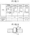
- FIGS. 1 - 11 illustrate a method in accordance with a first embodiment of the present invention.
- FIG. 12 illustrates an apparatus in accordance with a second embodiment of the present invention.
- FIG. 13 illustrates an apparatus in accordance with a third embodiment of the present invention.
- FIGS. 14 - 18 illustrate aspects of a method in accordance with the fourth embodiment of the present invention. Throughout all of the embodiments of the present invention, portions common to all of the embodiments are denoted with the same reference numerals.
- a method for manufacturing a cup-shaped article 17, in accordance with the present invention includes drawing a flat plate material portion 24 into a first cup-shaped configuration 16 having a cylinder portion with a decreasing thickness therealong and a bottom portion.
- the first cup-shaped configuration 16 is then formed into a second cup-shaped configuration 15, having a cylinder portion with a substantially uniform thickness therealong and a bottom portion, by increasing a thickness of the reduced thickness portion of the cylinder portion of the first cup-shaped configuration 16 through plastic working.
- the second cup-shaped configuration 15 is formed into a final cup-shaped article 17 by ironing the cylinder portion of the second cup-shaped configuration 15.
- the method for manufacturing a cup-shaped article 17 may include a step of providing a circular and substantially flat material portion 24 having a substantially uniform thickness, prior to the drawing step.
- the above-described thickness increasing step may be omitted when a flat plate material portion 25, 26, which is thicker at a radially inner portion thereof compared to a radially outer portion, is used as the flat plate material portion for the drawing step.
- the plastic working step includes coining or axial compression.
- a thickness increasing step is provided between the drawing step and the ironing step, or a flat plate material portion 25, 26 which is thicker at a central portion than a peripheral portion is used for the drawing step.
- the flat plate material portion 24 is drawn by a punch 27 and a die 28 into the cup-shaped configuration 16.
- a clearance between the punch 27 and the die 28 is greater than a thickness of the flat plate material portion 24, so that the flat plate material portion 24 is not ironed during the drawing process.
- the punch 27 and the die 28 have a clearance therebetween equal to about 1.1 times a thickness of the flat plate material portion 24.
- the first cup-shaped configuration 16 thus drawn, as shown in FIG. 1, has a relatively small thickness at a portion of the cylinder portion close to the bottom portion, and a relatively large thickness at a portion of the cylinder portion close to its open end. Therefore, a diametrical dimensional accuracy of the first cup-shaped configuration 16 is low.
- a part of the cylinder portion is moved or shifted to the reduced thickness portion (the portion of the cylinder portion close to the bottom portion) from a surrounding portion by plastic working, so that the cylinder portion of the second cup-shaped configuration 15 has a substantially uniform thickness along its entire length.
- This material shift is effected by coining in the first embodiment of the present invention, and by axial compression in the second and third embodiments of the present invention.
- the second cup-shaped configuration 15 is ironed by a punch 18 and a die 19 into a final cup-shaped article 17.
- the cup-shaped article 17 has a decreased thickness and an increased length.
- a clearance between the punch 18 and the die 19 is smaller than a thickness of the cylinder portion of the second cup-shaped configuration 15.
- An ironing rate i.e., thickness reduction rate
- diametrical dimensional variance of the cup-shaped article 17 manufactured according to the present invention is less than 3 microns, while that of a product manufactured according to the conventional method is as much as 30 microns.
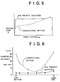
- FIG. 3 coining applied to the bottom portion of the first cup-shaped configuration 16 is used to increase the thickness of the reduced thickness portion of the cylinder portion of the first cup-shaped configuration 16.
- a right half of FIG. 3 illustrates a state before coining and a left half of FIG. 3 illustrates a state after coining.
- an upper die 1 is coupled to a press ram (not shown), and the punch 2 is fixed to the upper die by, for example, a retainer 3 and bolts 6.
- An ejecting rod 4 is provided for ejecting the formed second cup-shaped configuration 15 from the punch 2.
- the rod 4 is biased by, for example, a hydraulic cylinder, an air cylinder, or a spring (not shown) to push the second cup-shaped configuration 15 toward a tip of the punch 2 via a plate 5 coupled to an end of the rod 4.
- a lower die 8 is coupled to a bed (not shown) of the press machine.
- a generally cylindrical guide 9 is fit in a guide mounting hole formed in the lower die 8, and a lower punch 13 for coining is slidably fit within the cylindrical guide 9.
- the guide 9 is fixed to the lower die 8 by, for example, a retainer 10 and bolts 11.
- a material guide 12 is also fit in the retainer 10.
- the lower punch 13 is moved by a lower rod 14.
- the lower rod 14 is driven by, for example, a hydraulic cylinder or an air cylinder (not shown).
- the lower punch 13 may be biased upwardly by means of a spring, urethane rubber, or a belleville spring.
- the first cup-shaped configuration 16 is set in the material guide 12. At this stage, the lower punch 13 is raised to a position shown in the right half of FIG. 3. When forming is performed, the first cup-shaped configuration 16 is squeezed between the upper punch 2 and the lower punch 13, and is lowered, restricted by an inside surface of the guide 9, until the lower punch 13 comes into interference with the lower die 8. The bottom portion of the first cup-shaped configuration 16 is coined by a protrusion 13a formed in the lower punch 13. The coined wall portion is moved toward the reduced thickness portion of the cylinder portion of the first cup-shaped configuration 16, so that the first cup-shaped configuration 16 is plastically formed into the second cup-shaped configuration 15 having a cylinder portion with substantially uniform thickness.
- FIGS. 7, 8 and 9 illustrate some preferred configurations of punches for coining.
- the punches of FIG. 7 include a lower punch 13 having a concave for receiving a porion of the shifted wall material therein at a central portion of the punch 13.
- the lower punch 13 having an outside diameter d0 has a concave having diameter d1, and depth x.
- the punches of FIG. 8 include an upper punch 2' having a concave for receiving a portion of the shifted wall material therein at a central portion of the punch 2'.
- the punches of FIG. 9 include an upper punch 2 and a lower punch 13' each having flat end surfaces.
- the coining load is relatively low using A and B types, which are preferable in terms of length of functional life and a forming energy.
- FIG. 10 illustrates a relationship between the diametrical dimensional accuracy of the cylinder portion of the second cup-shaped configuration 15 and the coining rate of the bottom portion of the second cup-shaped configuration 15 when the coining is performed using the punches of FIG. 7.
- coining rate is defined as (1 - T1/T) ⁇ 100% , where T1 is a thickness of a radially outer portion of the bottom portion after coining and T is a thickness of the radially outer portion of the bottom portion before coining which is equal to a thickness of the cylinder portion (see FIG. 7).
- the diametrical dimensional accuracy of the cylinder portion of the second cup-shaped configuration 15 is greatly improved at coining rates of about 30% to about 50%.
- Coining may be performed as a last stage of the drawing step, whereby the manufacturing cycle time period can be shortened and the press machine can be compact. Further, coining may be performed any time before ironing.
- axial compression applied to the cylinder portion of the first cup-shaped configuration 16 is used as the form of plastic working to increase the thickness of the reduced thickness portion of the cylinder portion of the first cup-shaped configuration 16. More particularly, the first cup-shaped configuration 16 is set in a die 21 and is then compressed with a punch 20 having a stepped portion at a side surface thereof. This is a buckling forming with a buckling amount x', as seen in FIG. 12. The buckling starts at the reduced thickness portion, where a clearance between the first cup-shaped configuration 16 and the die 21 is large.
- axial compression is applied to the cylinder portion of the first cup-shaped configuration 16, as in the second embodiment of the present invention.
- the upper punch in divided into two portions, i.e., a main body 20 and a sleeve 20'.
- the bottom portion of the first cup-shaped configuration 16 is first squeezed by the main body 20 and the lower punch.
- the cylinder portion of the first cup-shaped configuration 16 is then axially compressed by the sleeve 20'.
- a method for manufacturing a cup-shaped article 17 includes a step, prior to the drawing step, of manufacturing a circular flat plate material portion 29 which is thicker at a radially inner portion thereof than at a radially outer portion thereof. Then, the plate material portion 29 is drawn into a cup-shaped configuration 15. The cup-shaped configuration 15 is then ironed into a final cup-shaped article 17. According to this method, coining and axial compression to increase the reduced thickness portion of the cylinder portion are not necessary, so that it is possible to reduce the cost of the final article.
- a thickness ratio between a portion of the flat plate material portion 29 corresponding to the cylinder portion of the cup-shaped configuration 15 and a portion of the flat plate material portion 29 corresponding to the bottom portion of the cup-shaped configuration 15 is determined so that, after drawing, the cylinder portion of the cup-shaped configuration 15 has a substantially uniform thickness over its entire axial length.
- FIG. 14 illustrates the flat plate material portion 29, wherein its greatest thickness T is at the central portion thereof, which gradually decreases in thickness toward a radially outward edge of the plate to the smallest thickness T2.
- thickness T3 at the open end of the cylinder portion of the cup-shaped configuration 15 will be substantially equal to thickness T4 at a portion of the cylinder portion close to the bottom portion, as shown in FIG. 15.
- the ironing load will be constant along the cylinder portion. Therefore, as shown in FIG. 16, a cup-shaped article 17 having a high diametrical dimensional accuracy is obtained.
- variable thickness flat plate may be a plate 25 manufactured by coining a flat plate, as shown in FIG. 17, or it may be a plate 26 manufactured by pressing a flat plate, as shown in FIG. 18.
- the second cup-shaped configuration 15 has a uniform thickness along its cylinder portion. Therefore, the ironing load is constant along the cylinder portion and distortion of the die is uniform. As a result, the diametrical dimensional accuracy of the final cup-shaped article 17 is greatly improved.
- the thickness of the cylinder portion is made uniform over an entire length thereof. Further, the axial length of the cylinder portion can be adjusted.
- a cup-shaped configuration having a substantially uniform thickness over an entire length of its cylinder portion can be obtained after drawing, without needing a thickness increasing step. As a result, a lower cost for manufacturing the cup-shaped article 17 is realized.
- a method for manufacturing a cup-shaped article (17) includes making the thickness of a cylinder portion of a cup-shaped configuration (15) uniform, between a step of drawing a flat plate material portion (24) into a cup-shaped configuration (16) and a step of ironing the cup-shaped configuration (15) into a final cup-shaped article (17).
- Increasing the thickness may be performed by coining or axial compression.
- the thickness increasing step may be replaced by a step, provided prior to the drawing step, of providing a plate material portion (25, 26) having a greater thickness at a radially inner portion than at a radially outer portion.
Landscapes
- Engineering & Computer Science (AREA)
- Mechanical Engineering (AREA)
- Shaping Metal By Deep-Drawing, Or The Like (AREA)
- Forging (AREA)
Applications Claiming Priority (3)
| Application Number | Priority Date | Filing Date | Title |
|---|---|---|---|
| JP28645494A JP3579936B2 (ja) | 1994-11-21 | 1994-11-21 | 有底筒状製品の成形方法 |
| JP28645494 | 1994-11-21 | ||
| JP286454/94 | 1994-11-21 |
Publications (3)
| Publication Number | Publication Date |
|---|---|
| EP0715908A2 true EP0715908A2 (de) | 1996-06-12 |
| EP0715908A3 EP0715908A3 (de) | 1997-02-26 |
| EP0715908B1 EP0715908B1 (de) | 2002-02-27 |
Family
ID=17704606
Family Applications (1)
| Application Number | Title | Priority Date | Filing Date |
|---|---|---|---|
| EP95118233A Expired - Lifetime EP0715908B1 (de) | 1994-11-21 | 1995-11-20 | Verfahren zum Hestellen eines becherförmigen Teils |
Country Status (5)
| Country | Link |
|---|---|
| US (1) | US5722282A (de) |
| EP (1) | EP0715908B1 (de) |
| JP (1) | JP3579936B2 (de) |
| KR (1) | KR100195371B1 (de) |
| DE (1) | DE69525596T2 (de) |
Cited By (4)
| Publication number | Priority date | Publication date | Assignee | Title |
|---|---|---|---|---|
| WO2009071437A1 (de) * | 2007-12-07 | 2009-06-11 | Thyssenkrupp Steel Ag | HERSTELLVERFAHREN HOCH MAßHALTIGER HALBSCHALEN |
| US8661686B2 (en) | 2003-09-16 | 2014-03-04 | Ntn Corporation | Method of manufacturing a shell type needle roller bearing including drawing and ironing operations |
| WO2017174425A1 (de) * | 2016-04-04 | 2017-10-12 | Thyssenkrupp Steel Europe Ag | Verfahren und vorrichtung zum umformen eines halbzeugs |
| EP3409394A4 (de) * | 2016-03-03 | 2019-05-08 | Nisshin Steel Co., Ltd. | Verfahren zur herstellung eines gegossenen elements |
Families Citing this family (17)
| Publication number | Priority date | Publication date | Assignee | Title |
|---|---|---|---|---|
| JP3505383B2 (ja) * | 1998-03-19 | 2004-03-08 | 三菱電機株式会社 | 直流電動機および直流電動機ヨークの製造方法 |
| KR20020057473A (ko) * | 2001-01-05 | 2002-07-11 | 서원표 | 실린더타입 부품의 성형방법 및 장치 |
| US6505492B2 (en) | 2001-04-11 | 2003-01-14 | Bethlehem Steel Corporation | Method and apparatus for forming deep-drawn articles |
| ITMN20040032A1 (it) * | 2004-11-18 | 2005-02-18 | Attrezzeria Mv & C Snc | Procedimento per ottenere un elemento cavo monolitico in lega di alluminio dotato di maniglie, ed elemento ottenuto. |
| JP5008306B2 (ja) * | 2006-01-05 | 2012-08-22 | 日新製鋼株式会社 | バックルベース部材のダボ出し加工方法 |
| JP4702843B2 (ja) * | 2006-03-29 | 2011-06-15 | 旭精機工業株式会社 | 筒形成形品の製造方法及び金型 |
| US20090158580A1 (en) * | 2007-06-18 | 2009-06-25 | Precision Valve Corporation | Method of making aerosol valve mounting cups and resultant cups |
| US8118197B2 (en) * | 2007-06-18 | 2012-02-21 | Precision Valve Corporation | Method of making aerosol valve mounting cups and resultant cups |
| DE102008018656B9 (de) * | 2008-04-11 | 2009-07-09 | Thyssenkrupp Steel Ag | Verfahren zur Herstellung von hochmaßhaltigen Halbschalen |
| EP2834025A1 (de) * | 2012-04-02 | 2015-02-11 | Adval Tech Holding AG | Verfahren zur herstellung von topfförmigen bauteilen in einem umformprozess |
| KR101644765B1 (ko) | 2013-01-09 | 2016-08-01 | 신닛테츠스미킨 카부시키카이샤 | 프레스 성형 방법 |
| CN105188983B (zh) | 2013-05-08 | 2016-12-07 | 新日铁住金株式会社 | 带有凸台的圆筒容器的成形方法 |
| JP6352065B2 (ja) * | 2014-06-13 | 2018-07-04 | 日新製鋼株式会社 | 成形材製造方法 |
| JP6776768B2 (ja) * | 2016-09-27 | 2020-10-28 | 東洋製罐株式会社 | 角形缶の製造方法 |
| KR102062228B1 (ko) * | 2018-04-27 | 2020-01-03 | 주식회사전우정밀 | 절곡부위를 증육드로잉하는 드로잉 장치 및 그 작동방법 |
| KR102062229B1 (ko) * | 2018-04-27 | 2020-01-03 | 주식회사전우정밀 | 복수 개의 절곡부위를 증육드로잉하는 복합 증육 드로잉 장치 및 그 작동방법 |
| JP7539241B2 (ja) | 2020-03-27 | 2024-08-23 | 大和製罐株式会社 | 電池ケースの製造方法 |
Family Cites Families (17)
| Publication number | Priority date | Publication date | Assignee | Title |
|---|---|---|---|---|
| US2770034A (en) * | 1952-03-14 | 1956-11-13 | Lyon George Albert | Method of coining and cupping metal |
| US2877546A (en) * | 1953-06-09 | 1959-03-17 | Motor Wheel Corp | Method for forming tubular metal articles |
| US2776475A (en) * | 1953-09-30 | 1957-01-08 | Specialties Dev Corp | Method of making cylindrical metallic containers for confining fluid medium under pressure |
| US2875511A (en) * | 1955-04-28 | 1959-03-03 | Turner C Hawes | Method for coining blanks for deep drawn cylinders, and product thereof |
| GB1050358A (de) * | 1963-10-01 | |||
| DE1752186A1 (de) * | 1968-04-17 | 1971-04-08 | Vaw Ver Aluminium Werke Ag | Verfahren zur Erhoehung des Tiefziehverhaeltnisses beim Tiefziehen von Metallen,insbesondere Aluminiumwerkstoffen |
| US4339939A (en) * | 1977-06-16 | 1982-07-20 | Textron, Inc. | Drawing heavy walled parts |
| US4129024A (en) * | 1977-11-09 | 1978-12-12 | Aluminum Company Of America | Method and apparatus for forming elongated, tapered wall shells |
| JPS597430A (ja) * | 1982-07-07 | 1984-01-14 | Hitachi Ltd | 絞り成形法 |
| US4527413A (en) * | 1982-08-13 | 1985-07-09 | Verson Allsteel Press Company | Apparatus for drawing heavy wall shells with a multi-step inside edge |
| US4509356A (en) * | 1982-08-13 | 1985-04-09 | Verson Allsteel Press Co. | Method and apparatus for drawing heavy wall shells |
| JPS60102240A (ja) * | 1983-11-09 | 1985-06-06 | Aisin Seiki Co Ltd | 鈑金製ポリvプ−リの製造方法 |
| US5209099A (en) * | 1985-03-15 | 1993-05-11 | Weirton Steel Corporation | Draw-process methods, systems and tooling for fabricating one-piece can bodies |
| JPH07102407B2 (ja) * | 1990-03-14 | 1995-11-08 | 日産自動車株式会社 | 円筒状ワークのプレス成形方法 |
| US5149238A (en) * | 1991-01-30 | 1992-09-22 | The Stolle Corporation | Pressure resistant sheet metal end closure |
| US5329799A (en) * | 1992-05-29 | 1994-07-19 | Toyota Jidosha Kabushiki Kaisha | Process and apparatus for press-forming tubular container-like article from strip, including forward and backward ironing steps |
| JP2982494B2 (ja) * | 1992-05-29 | 1999-11-22 | トヨタ自動車株式会社 | 板状の素材を円筒容器状に成形するプレス法 |
-
1994
- 1994-11-21 JP JP28645494A patent/JP3579936B2/ja not_active Expired - Fee Related
-
1995
- 1995-10-12 KR KR1019950035021A patent/KR100195371B1/ko not_active Expired - Fee Related
- 1995-11-20 EP EP95118233A patent/EP0715908B1/de not_active Expired - Lifetime
- 1995-11-20 DE DE69525596T patent/DE69525596T2/de not_active Expired - Fee Related
-
1997
- 1997-05-09 US US08/853,672 patent/US5722282A/en not_active Expired - Fee Related
Cited By (6)
| Publication number | Priority date | Publication date | Assignee | Title |
|---|---|---|---|---|
| US8661686B2 (en) | 2003-09-16 | 2014-03-04 | Ntn Corporation | Method of manufacturing a shell type needle roller bearing including drawing and ironing operations |
| WO2009071437A1 (de) * | 2007-12-07 | 2009-06-11 | Thyssenkrupp Steel Ag | HERSTELLVERFAHREN HOCH MAßHALTIGER HALBSCHALEN |
| EP3409394A4 (de) * | 2016-03-03 | 2019-05-08 | Nisshin Steel Co., Ltd. | Verfahren zur herstellung eines gegossenen elements |
| US10456820B2 (en) | 2016-03-03 | 2019-10-29 | Nippon Steel Nisshin Co., Ltd. | Method for manufacturing molded member |
| WO2017174425A1 (de) * | 2016-04-04 | 2017-10-12 | Thyssenkrupp Steel Europe Ag | Verfahren und vorrichtung zum umformen eines halbzeugs |
| US11192162B2 (en) | 2016-04-04 | 2021-12-07 | Thyssenkrupp Steel Europe Ag | Method and device for forming a semi-finished product |
Also Published As
| Publication number | Publication date |
|---|---|
| KR960016995A (ko) | 1996-06-17 |
| JPH08141662A (ja) | 1996-06-04 |
| EP0715908A3 (de) | 1997-02-26 |
| JP3579936B2 (ja) | 2004-10-20 |
| EP0715908B1 (de) | 2002-02-27 |
| US5722282A (en) | 1998-03-03 |
| DE69525596D1 (de) | 2002-04-04 |
| KR100195371B1 (ko) | 1999-06-15 |
| DE69525596T2 (de) | 2002-07-18 |
Similar Documents
| Publication | Publication Date | Title |
|---|---|---|
| EP0715908A2 (de) | Verfahren zum Hestellen eines becherförmigen Teils | |
| US5746085A (en) | Gear forming method | |
| KR100322280B1 (ko) | 계단식 판금제 프레스 성형품에 있어서의 스플라인 치형의 인장성형방법 및 그 방법에 따른 인장성형 판금제 클러치드럼 | |
| US7624611B2 (en) | Method and apparatus for forming a cup-shaped member | |
| JP3394332B2 (ja) | バーリング加工方法 | |
| JP3131880B2 (ja) | 二重筒体の製造方法 | |
| JPH0433728A (ja) | バーリング加工方法 | |
| GB2066412A (en) | Punch Press Assembly Including a Preloaded Encapsulated Spring and Method of Manufacture | |
| JP3671760B2 (ja) | リング部材の成形方法およびプレス機 | |
| JPH0732052A (ja) | コルゲート管の加工方法およびその装置 | |
| KR100258518B1 (ko) | 관체의 가공 방법 | |
| JP2592139B2 (ja) | 等速ジョイント外輪の製造方法および製造装置 | |
| US3935627A (en) | Method of making sheet metal pulley | |
| JPH11314128A (ja) | 長手方向中間部内面に縦溝を有するパイプの製造方法 | |
| JPH01317627A (ja) | 液圧バルジ成形法 | |
| JP2000312946A (ja) | 各種シャフト及びその塑性加工方法 | |
| JPH05317955A (ja) | 鍔付筒状部材の成形方法及び成形装置並びに鍔付筒状部材 | |
| RU2082525C1 (ru) | Способ глубокой вытяжки | |
| JP2000084639A (ja) | 長尺管のセレーション加工装置 | |
| JP3810261B2 (ja) | 内周溝付き焼結軸受の製造方法および溝加工装置 | |
| JP2812954B2 (ja) | ストラットマウント用内筒のベアリング保持爪形成方法 | |
| JP3232900B2 (ja) | バルジニップルの製造方法 | |
| CA1151062A (en) | Punch press assembly including a preloaded encapsulated spring and method of manufacture | |
| JPH0417938A (ja) | 歯車素材の製造方法及びその装置 | |
| RU2116853C1 (ru) | Способ образования отбортовок в широкофланцевых деталях |
Legal Events
| Date | Code | Title | Description |
|---|---|---|---|
| PUAI | Public reference made under article 153(3) epc to a published international application that has entered the european phase |
Free format text: ORIGINAL CODE: 0009012 |
|
| 17P | Request for examination filed |
Effective date: 19951120 |
|
| AK | Designated contracting states |
Kind code of ref document: A2 Designated state(s): DE FR GB |
|
| RHK1 | Main classification (correction) |
Ipc: B21D 22/21 |
|
| PUAL | Search report despatched |
Free format text: ORIGINAL CODE: 0009013 |
|
| AK | Designated contracting states |
Kind code of ref document: A3 Designated state(s): DE FR GB |
|
| 17Q | First examination report despatched |
Effective date: 19980401 |
|
| GRAG | Despatch of communication of intention to grant |
Free format text: ORIGINAL CODE: EPIDOS AGRA |
|
| GRAG | Despatch of communication of intention to grant |
Free format text: ORIGINAL CODE: EPIDOS AGRA |
|
| GRAH | Despatch of communication of intention to grant a patent |
Free format text: ORIGINAL CODE: EPIDOS IGRA |
|
| GRAH | Despatch of communication of intention to grant a patent |
Free format text: ORIGINAL CODE: EPIDOS IGRA |
|
| REG | Reference to a national code |
Ref country code: GB Ref legal event code: IF02 |
|
| GRAA | (expected) grant |
Free format text: ORIGINAL CODE: 0009210 |
|
| RAP1 | Party data changed (applicant data changed or rights of an application transferred) |
Owner name: TOYOTA JIDOSHA KABUSHIKI KAISHA |
|
| AK | Designated contracting states |
Kind code of ref document: B1 Designated state(s): DE FR GB |
|
| REF | Corresponds to: |
Ref document number: 69525596 Country of ref document: DE Date of ref document: 20020404 |
|
| PLBE | No opposition filed within time limit |
Free format text: ORIGINAL CODE: 0009261 |
|
| STAA | Information on the status of an ep patent application or granted ep patent |
Free format text: STATUS: NO OPPOSITION FILED WITHIN TIME LIMIT |
|
| 26N | No opposition filed |
Effective date: 20021128 |
|
| REG | Reference to a national code |
Ref country code: GB Ref legal event code: 746 Effective date: 20041018 |
|
| REG | Reference to a national code |
Ref country code: FR Ref legal event code: D6 |
|
| PGFP | Annual fee paid to national office [announced via postgrant information from national office to epo] |
Ref country code: DE Payment date: 20081114 Year of fee payment: 14 |
|
| PGFP | Annual fee paid to national office [announced via postgrant information from national office to epo] |
Ref country code: FR Payment date: 20081112 Year of fee payment: 14 |
|
| PGFP | Annual fee paid to national office [announced via postgrant information from national office to epo] |
Ref country code: GB Payment date: 20081119 Year of fee payment: 14 |
|
| GBPC | Gb: european patent ceased through non-payment of renewal fee |
Effective date: 20091120 |
|
| REG | Reference to a national code |
Ref country code: FR Ref legal event code: ST Effective date: 20100730 |
|
| PG25 | Lapsed in a contracting state [announced via postgrant information from national office to epo] |
Ref country code: FR Free format text: LAPSE BECAUSE OF NON-PAYMENT OF DUE FEES Effective date: 20091130 |
|
| PG25 | Lapsed in a contracting state [announced via postgrant information from national office to epo] |
Ref country code: DE Free format text: LAPSE BECAUSE OF NON-PAYMENT OF DUE FEES Effective date: 20100601 |
|
| PG25 | Lapsed in a contracting state [announced via postgrant information from national office to epo] |
Ref country code: GB Free format text: LAPSE BECAUSE OF NON-PAYMENT OF DUE FEES Effective date: 20091120 |