EP0715552B1 - Pliage adaptatif - Google Patents
Pliage adaptatif Download PDFInfo
- Publication number
- EP0715552B1 EP0715552B1 EP94924653A EP94924653A EP0715552B1 EP 0715552 B1 EP0715552 B1 EP 0715552B1 EP 94924653 A EP94924653 A EP 94924653A EP 94924653 A EP94924653 A EP 94924653A EP 0715552 B1 EP0715552 B1 EP 0715552B1
- Authority
- EP
- European Patent Office
- Prior art keywords
- folding
- sheet
- angle
- pressure means
- die
- Prior art date
- Legal status (The legal status is an assumption and is not a legal conclusion. Google has not performed a legal analysis and makes no representation as to the accuracy of the status listed.)
- Expired - Lifetime
Links
- 230000003044 adaptive effect Effects 0.000 title description 4
- 238000000034 method Methods 0.000 claims abstract description 49
- 238000012937 correction Methods 0.000 claims abstract description 20
- 239000002184 metal Substances 0.000 claims abstract description 15
- 238000013213 extrapolation Methods 0.000 claims abstract description 7
- 238000003825 pressing Methods 0.000 claims abstract description 6
- 230000001105 regulatory effect Effects 0.000 claims abstract description 4
- 239000000700 radioactive tracer Substances 0.000 claims description 28
- 239000000463 material Substances 0.000 description 10
- 238000005096 rolling process Methods 0.000 description 3
- 238000005259 measurement Methods 0.000 description 2
- 238000005457 optimization Methods 0.000 description 2
- 238000005452 bending Methods 0.000 description 1
- 238000004364 calculation method Methods 0.000 description 1
- 230000003247 decreasing effect Effects 0.000 description 1
- 230000001939 inductive effect Effects 0.000 description 1
- 238000004519 manufacturing process Methods 0.000 description 1
- 238000013178 mathematical model Methods 0.000 description 1
Images

Classifications
-
- B—PERFORMING OPERATIONS; TRANSPORTING
- B21—MECHANICAL METAL-WORKING WITHOUT ESSENTIALLY REMOVING MATERIAL; PUNCHING METAL
- B21D—WORKING OR PROCESSING OF SHEET METAL OR METAL TUBES, RODS OR PROFILES WITHOUT ESSENTIALLY REMOVING MATERIAL; PUNCHING METAL
- B21D5/00—Bending sheet metal along straight lines, e.g. to form simple curves
- B21D5/02—Bending sheet metal along straight lines, e.g. to form simple curves on press brakes without making use of clamping means
-
- Y—GENERAL TAGGING OF NEW TECHNOLOGICAL DEVELOPMENTS; GENERAL TAGGING OF CROSS-SECTIONAL TECHNOLOGIES SPANNING OVER SEVERAL SECTIONS OF THE IPC; TECHNICAL SUBJECTS COVERED BY FORMER USPC CROSS-REFERENCE ART COLLECTIONS [XRACs] AND DIGESTS
- Y10—TECHNICAL SUBJECTS COVERED BY FORMER USPC
- Y10S—TECHNICAL SUBJECTS COVERED BY FORMER USPC CROSS-REFERENCE ART COLLECTIONS [XRACs] AND DIGESTS
- Y10S72/00—Metal deforming
- Y10S72/702—Overbending to compensate for springback
Definitions
- the present invention relates to a method (claims 1-10) and to a device (claims 11-16) for folding a metal sheet to a well-defined angle.
- a metal sheet is deformed in a recess of a die through a pressure means being moved above the recess, pressing on the sheet, towards the die until it reaches a well-defined end position.
- the punch is then raised again, and the sheet springs back elastically a little.
- the difference in angle between the situation in which the sheet is clamped between the punch in its minimal position and the vee-block and the situation in which the sheet is entirely clear of the tools is known as the spring-back.
- the Y-position which the punch must assume is determined by means of a folding formula or table.
- Folding formulae and tables only take account of the sheet thickness and the V-opening. They generally do not take account of material properties such as tensile strength and rolling direction, but the latter also influence the folding angle obtained. The folding angle actually obtained will therefore be only approximately the same as the desired folding angle.
- the angle obtained is measured. On the basis of the deviation in angle, a calculation of the correction necessary on the Y-position of the punch is made. A fold is made in a new sheet taking into account the correction in Y, and the result is measured again. This is iterated until the fold angle obtained lies within the desired accuracy limits.
- the folding formula which gives the Y-position as a function of the desired angle is only an approximation.
- the angle obtained greatly depends on the material used, the composition of the material, the texture of the material, the direction of the fold relative to the rolling direction, and the thickness of the material. All these parameters which influence the angle obtained ensure that, for each fold, the correction must be established experimentally in order to obtain a fold within the desired accuracy limits.
- the angle can also be measured in each case only after the sheet is clear of the tools, which is when the spring-back has been completed. It goes without saying that this experimental optimization of the folding angle is laborious and time-consuming. Moreover, it is always necessary to make a number of test pieces, which are wasted.
- the folding formula is incorporated in the control system.
- the operator thus merely has to enter his experimentally measured angle in the control system.
- the control system then automatically calculates the correction on the Y-position for the next test piece, but here again the angle is still measured manually, the optimization is still laborious, and worthless test pieces have to be made.
- the method according to the invention is a method by means of which the folding to the desired folding angle is optimized during the making of the fold, i.e. it is an adaptive folding method.
- a number of adaptive folding methods are known. Such methods are:
- Methods which measure the force as a function of the position of the punch aim to derive a number of material properties and thickness deviations therefrom.
- a mathematical model is then used with such data to forecast up to what position (lowering) the punch must go in order to obtain the desired angle.
- the force is measured by a force transducer (for example, strain gauges) which is disposed along the force path.
- the position is given by the linear encoders already present on the folding press.
- the vision system also works with standard tools, but it has great limitations. It often happens that an edge which has already been folded impedes the projection of the fold. In those cases the system cannot work because of the absence of measurement.
- a special vee-block which generates a signal which changes as a function of the distance of the sheet in the vee-block from the wall inside the vee-block, is used. It is generally a variant of inductive measuring of a position.
- the side walls of the vee-block itself are rotatable, and the angle thereof is measured.
- the vee-block broadens as a result, so that the same disadvantages as those of the other known methods apply.
- the contact piece is on the outside of the vee-block, which again prevents short folding.
- the method according to the invention i.e. an adaptive folding method, is a method by means of which excellent folding results can be obtained, even if the properties of the sheets vary.
- the method according to the invention is a method in which a metal sheet is deformed in a recess of a die through a pressure means being moved above the recess, pressing on the sheet, towards the die until it reaches a well-defined end position.
- Said method is characterized in that the movement of the pressure means is regulated as a function of the folding force and of the folding angle in order, on the one hand, to obtain a well-defined angle before the spring-back of the sheet and, on the other hand, to compensate for the spring-back of the sheet, so that after the spring-back the desired angle is obtained.
- dY/dD the differential which is determined from the course of the folding angle as a function of the position of the pressure means
- the folding force can be measured in a multiplicity of pressure pieces disposed below the die and/or with the aid of strain gauges.
- the half folding angle is preferably measured by determining the coordinates of one point on the underside of the sheet and by determining the gradient of the straight line through said point and touching the lead curve of the die, and the folding angle is taken as double the half folding angle.
- Said half folding angle is advantageously measured on either side of the fold in the sheet, and the folding angle is taken as the sum of the two half folding angles.
- a tracer is placed in a reference position by a means, such as a stop, provided thereon.
- Said tracer contains a telescopic element which is placed against the underside of the sheet, as a result of which the coordinates of a point on the underside of the sheet are calculated from the position of the telescopic element.
- the present invention also relates to a device for folding a sheet, comprising a table on which a die is disposed and a pressure means for folding a sheet in a recess provided for the purpose.
- a multiplicity of pressure pieces is disposed in the table below the die, strain gauges being fitted in said pressure pieces for the purpose of measuring the folding force.
- the device comprises a tracer (e.g. movably disposed) for measuring the angle, which tracer is provided at one end with a telescopic element and with a means for setting up the tracer in a reference position, which telescopic element in this reference position can be extended until it is against the underside of a sheet placed on the die.
- a tracer e.g. movably disposed
- the tracer is provided at one end with a telescopic element and with a means for setting up the tracer in a reference position, which telescopic element in this reference position can be extended until it is against the underside of a sheet placed on the die.
- the device advantageously also comprises means for recording the extended position of said element and for determining the folding angle of the sheet from said position.
- a calibration block can be used to determine the relation between the signal generated by the tracer and the folding angle.
- one end of at least one lever is rotatably fixed to the tracer, while the other end of said lever is rotatably fixed to a fixed part of the device.
- the device also comprises an immovably fixed actuator, a part of which can be driven so that it assumes at least two positions. Said part is rotatably fixed to a lever, so that in a first position of said part the tracer assumes the reference position, and in a second position of said part the tracer is positioned outside the working range of the die.
- a metal sheet 2 is folded to a well-defined angle Dw through deformation of the sheet 2 in a recess 31 of a die 3.
- a pressure means 1 is moved above the recess 31, pressing on the sheet 2, towards the die 3 to a well-defined end position Ya.
- the punch 1 is driven towards said calculated position Yt, as a result of which the sheet 2 is folded.
- the course D(Y) as a function of the position Y or the movement of the punch 1 is measured.
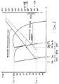
- the difference between the desired angle Dw and the angle Dt obtained is called dDw.
- the value dYw is calculated as dDw x dY/dD . This is the depth compensation which would be necessary to obtain the desired angle Dw without taking spring-back into account.
- the force present at that moment is called Ft and considered to be equal to 100%.
- the punch is now driven upwards until the force has decreased to Fe, which is x% of the force Ft.
- a position Ye is now reached.
- the value Yr is determined from the regression of the curve F(Y) between Yt and Ye.
- Yr Yt (1 - ⁇ ) , in which ⁇ is ⁇ constant for a type of sheet and can be calculated, for example, as follows: a ⁇ Yt - Ye Ft - Fe x 100 in which Y is the distance between die and punch. dY/dD can easily be determined from the course D(Y) as a function of Y.
- dY/dD can be determined as follows: Yt - Yf/ Dt - Df
- each fold is thus made in 3 phases: The punch first goes down to position Yt or Yw, then comes up a little (e.g. to position Ye if the punch was moved in the first step to position Yt), and then goes down to the final position.
- the force is measured by measuring the deformation somewhere along the force path. This is carried out by means of strain gauges which are fitted in the pressure pieces 17 of the bending table 16. The signal from the strain gauges is a measure of the force which the machine undergoes as a result of the material to be folded.
- a force transducer is built into each pressure piece.
- the force where the folding is being carried out can always be measured by said force transducer. Even in the case of short, thin sheets requiring only a small folding force, this ensures that an accurate force signal can still be obtained.
- the coordinates of the point on the underside of the sheet are calculated from the position of the pin 4 of a distance sensor 8.
- the distance sensor thus has the function of a tracer, and is called a tracer below.
- the signal from the tracer is a measure of the folding angle.
- the tracer is positioned only when the fold is being made. In order to achieve the movement of the tracer, it is connected in the hinges 5 and 7 to two levers 9 and 6.
- the lower lever 9 is immovably fixed in hinge 13 and is driven in hinge 12 by an actuator 14.
- the actuator is, for example, a pneumatic cylinder.
- Lever 6 has hinge 11 as the fixed centre of rotation.
- the reference position of the tracer is determined through stop 10, which is immovably connected to the tracer 8, striking against the vee-block 3 (see Fig. 2).
- the actual folding angle D(Y) is measured, in particular continuously, for various movements Y, as a result of which the course of D(Y) is determined.
- the differential dY/dD is measured in the region of Dt for the course D(Y), as a result of which the correction dYw of the movement of the punch 1 is calculated, in order to obtain the desired folding angle.
- dYw (Dt [114°] - Dw [90°]) dY dD
- the force Ft for obtaining the actual final folding angle Dt (114°) is measured.
- the force F exerted on the sheet 2 is reduced.
- the movement of the punch 1 is controlled until a certain force Fe, which is preferably lower than 50% of Ft, e.g. 30% of Ft, is obtained.
- the movement of the punch Ye until Fe is obtained is measured.
Landscapes
- Engineering & Computer Science (AREA)
- Mechanical Engineering (AREA)
- Bending Of Plates, Rods, And Pipes (AREA)
- Folding Of Thin Sheet-Like Materials, Special Discharging Devices, And Others (AREA)
- Shaping Metal By Deep-Drawing, Or The Like (AREA)
Abstract
Claims (16)
- Procédé pour plier une tôle métallique (2) sur un angle (Dw) bien défini, dans lequel la tôle (2) est déformée dans un creux (31) d'une matrice (3), par l' intermédiaire d'un moyen de pressage (1) déplacé au-dessus du creux (31), qui presse la tôle (2) en direction de la matrice (3) jusqu'à atteindre une position finale (Ya) bien définie, dans lequel le déplacement du moyen de pressage est réglé en fonction de la force de pliage et de l'angle de pliage en vue d'une part d'obtenir un angle bien défini avant le retour élastique de la tôle (2), et d'autre part de compenser le retour élastique de la tôle de telle sorte qu'après le retour élastique on obtienne l'angle (Dw) voulu, ledit procédé comprenant les étapes suivantes :a. le moyen de pressage est entraîné en direction d'une position (Yt) qui est calculée au moyen d'une formule de pliage théorique, et pendant que le moyen de pressage est déplacé vers la matrice et que la tôle est ainsi pliée, l'évolution de l'angle de pliage (D) en fonction de la position (Y) du moyen de pressage est mesurée au moins dans la région de la position calculée (Yt), avec pour résultat que dYw, qui est la correction de la position du moyen de pressage (1) qui est nécessaire pour obtenir l'angle bien défini avant le retour élastique de la tôle (2), est déterminée par extrapolation de l'évolution (D(Y)) de l'angle de pliage (D) en fonction de la position (Y) du moyen de pressage (1),b. le moyen de pressage est arrêté lorsqu'il atteint une position calculée, ladite position calculée étant la position (Yt) calculée au moyen de la formule théorique ou la position correspondant à Yt (position calculée) - dYw,c. le moyen de pressage (1) est éloigné de la matrice (3) sur une distance arbitraire, de telle sorte qu'il se produit un retour élastique de la tôle (2), tandis que l'évolution (F(Y)) de la force de pliage (F) en fonction de la position (Y) du moyen de pressage (1) est mesurée,d. le moyen de pressage (1) est déplacé dans la direction de la matrice (3) jusqu'à ce qu'il se trouve dans une position finale (Ya) qui est calculée pendant l'opération qui suit, conformément à la formule:

dYw est la correction de la position du moyen de pressage (1) qui est nécessaire pour obtenir l'angle (Dw) bien défini avant le retour élastique de la tôle (2), et qui est déterminée en fonction de la position (Y) du moyen de pressage (1), par extrapolation de l'évolution (D(Y)) de l'angle de pliage (D). - Procédé selon la revendication 1, caractérisé en ce que le moyen de pressage (1) est déplacé jusqu'à ce qu'il atteigne la position Yt (position calculée) - dYw, tandis que dYr est calculé comme étant

- Procédé pour plier une tôle métallique (2) sur un angle bien défini selon la revendication 2, caractérisé en ce que la correction (dYw) est calculée conformément à la formule:

- Procédé pour plier une tôle métallique (2) sur un angle bien défini selon les revendications 2 ou 3, caractérisé en ce que le moyen de pressage (1) est éloigné de la matrice (3) dans une position (Ye) dans laquelle le retour élastique de la tôle (2) n'est pas terminé, et en ce que la correction (dYr) est calculée conformément à la formule:

- Procédé pour plier une tôle métallique (2) sur un angle (Dw) bien défini selon l'une ou plusieurs des revendications précédentes, caractérisé en ce que la force de pliage (F) est mesurée dans l'une des pièces de pression (17) disposées en dessous de la matrice (3).
- Procédé pour plier une tôle métallique (2) sur un angle (Dw) bien défini selon l'une ou plusieurs des revendications précédentes, caractérisé en ce que la force de pliage (F) est mesurée au moyen de cellules de contrainte.
- Procédé pour plier une tôle métallique (2) sur un angle (Dw) bien défini selon l'une ou plusieurs des revendications précédentes, caractérisé en ce que le demi-angle de pliage (d) est mesuré en déterminant les coordonnées d'un point de la face inférieure de la tôle (2) et en déterminant le gradient de la ligne droite passant par ce point et touchant la courbe de guidage de la matrice (3), et en ce que l'angle de pliage (D) est pris comme étant le double du demi-angle de pliage (d).
- Procédé pour plier une tôle métallique (2) sur un angle (Dw) bien défini selon la revendication 7, caractérisé en ce que le demi-angle de pliage (d) est mesuré sur les deux côtés du pli de la tôle (2), et en ce que l'angle de pliage (D) est pris comme étant la somme des deux demi-angles de pliage (d).
- Procédé pour plier une tôle métallique (2) sur un angle (Dw) bien défini selon les revendications 7 ou 8, caractérisé en ce qu'un traceur (8) est placé dans une position de référence en plaçant une butée (10) prévue sur lui contre le côté de la matrice (3), en ce qu'un élément télescopique (4) dudit traceur (8) est placé contre la face inférieure de la tôle (2) et en ce que les coordonnées sont calculées à partir de la position de l'élément télescopique (4), en partant d'un point situé sur la face inférieure de la tôle (2).
- Procédé pour plier une tôle métallique (2) sur un angle (Dw) bien défini selon la revendication 9, caractérisé en ce que le traceur (8) est enlevé du voisinage de la matrice (3) lorsque l'angle de pliage (D) ne doit pas être mesuré.
- Dispositif pour plier une tôle (2), comprenant une table (15, 16) sur laquelle est disposée une matrice (3) et un moyen de pressage (1) pour plier une tôle (2) dans un creux (31) prévu à cet effet, caractérisé en ce que plusieurs pièces de pression (17) sont disposées dans la table (15, 16) en dessous de la matrice (3), et en ce que des cellules de contrainte sont disposées dans lesdites pièces de pression (17) pour mesurer la force de pliage (F), et en ce que le dispositif contient un moyen pour calculer la position finale du moyen de pressage pendant l'opération de pliage, selon un procédé selon l'une quelconque des revendications précédentes.
- Dispositif pour plier une tôle (2), comprenant:- une table (15, 16) sur laquelle est disposée une matrice (3),- un moyen de pressage (1) pour plier une tôle (2) dans un creux (31) prévu à cet effet,- un traceur (8) qui est doté à une extrémité d'un élément télescopique (4), et d'un moyen (10) pour disposer le traceur (8) dans une position de référence, lequel élément télescopique (4) placé dans cette position de référence peut être étendu jusqu'à se trouver contre la face inférieure d'une tôle (2) placée sur la matrice (3),- un moyen pour enregistrer la position étendue dudit élément (4) et pour déterminer l'angle de pliage (D) de la tôle (2) à partir de ladite position, et- un moyen pour calculer la position finale du moyen de pressage pendant l'opération de pliage, selon un procédé selon l'une quelconque des revendications précédentes.
- Dispositif pour plier une tôle (2) selon la revendication 12, caractérisé en ce que le traceur (8) est disposé de manière à pouvoir être déplacé.
- Dispositif pour plier une tôle (2) selon la revendication 13, caractérisé en ce qu'une extrémité d'au moins un levier (6), (9) est fixée à rotation au traceur (8), tandis que l'autre extrémité dudit levier (6), (9) est fixée à rotation à une partie fixe du dispositif, en ce que le dispositif comprend un dispositif d'actionnement (14) fixé de manière à ne pas pouvoir bouger, dont une partie (19) peut être entraînée de manière à prendre au moins deux positions, et en ce que la partie (19) mentionnée ci-dessus du dispositif d'actionnement (14) est fixée à rotation à un levier (6), (9) de telle sorte que dans une première position de ladite partie (19), le traceur (8) prenne la position de référence, et que dans une deuxième position de ladite partie (19), le traceur (8) est disposé à l'extérieur de la plage de travail de la matrice (3).
- Dispositif pour plier une tôle (2) selon la revendication 14, caractérisé en ce que le traceur (8) est disposé en dessous du niveau de la table (15, 16) lorsque la partie entraînée (19) du dispositif d'actionnement (14) se trouve dans ladite deuxième position.
- Dispositif pour plier une tôle (2) selon les revendications 14 ou 15, caractérisé en ce que le dispositif d'actionnement (14) est un vérin pneumatique dont la tige (19) du piston est fixée à rotation à un levier (6), (9).
Applications Claiming Priority (3)
| Application Number | Priority Date | Filing Date | Title |
|---|---|---|---|
| BE9300884 | 1993-08-27 | ||
| BE9300884A BE1007424A5 (nl) | 1993-08-27 | 1993-08-27 | Adaptief plooien. |
| PCT/BE1994/000052 WO1995005905A1 (fr) | 1993-08-27 | 1994-08-26 | Pliage adaptatif |
Publications (2)
| Publication Number | Publication Date |
|---|---|
| EP0715552A1 EP0715552A1 (fr) | 1996-06-12 |
| EP0715552B1 true EP0715552B1 (fr) | 1997-01-22 |
Family
ID=3887290
Family Applications (1)
| Application Number | Title | Priority Date | Filing Date |
|---|---|---|---|
| EP94924653A Expired - Lifetime EP0715552B1 (fr) | 1993-08-27 | 1994-08-26 | Pliage adaptatif |
Country Status (6)
| Country | Link |
|---|---|
| US (1) | US5829288A (fr) |
| EP (1) | EP0715552B1 (fr) |
| BE (1) | BE1007424A5 (fr) |
| DE (1) | DE69401594T2 (fr) |
| GB (1) | GB2282090B (fr) |
| WO (1) | WO1995005905A1 (fr) |
Cited By (1)
| Publication number | Priority date | Publication date | Assignee | Title |
|---|---|---|---|---|
| DE10006512A1 (de) * | 2000-02-15 | 2001-09-13 | Colgar Spa | Abkantpresse mit einer Vorrichtung zum Messen des Biegewinkels am Werkstück |
Families Citing this family (12)
| Publication number | Priority date | Publication date | Assignee | Title |
|---|---|---|---|---|
| DE59806982D1 (de) * | 1997-09-11 | 2003-02-27 | Komax Holding Ag Dierikon | Verfahren zur Bestimmung der Qualität einer Crimpverbindung |
| TW471340U (en) * | 2000-12-15 | 2002-01-01 | Hon Hai Prec Ind Co Ltd | Structure for lower knife mold of bending machine |
| FR2863785B1 (fr) * | 2003-12-11 | 2006-04-28 | Airbus France | Dispositif de sertissage d'un contact sur un cable |
| JP2006205256A (ja) * | 2004-12-27 | 2006-08-10 | Amada Co Ltd | ワークの曲げ角度検出装置およびワークの曲げ加工機 |
| CN102708222B (zh) * | 2006-08-31 | 2014-11-26 | 新日铁住金株式会社 | 回弹发生原因特定方法、回弹发生原因部位特定方法、回弹对策位置特定方法以及它们的装置 |
| US7754532B2 (en) * | 2006-10-19 | 2010-07-13 | Micron Technology, Inc. | High density chip packages, methods of forming, and systems including same |
| US9463500B1 (en) * | 2012-10-09 | 2016-10-11 | The Boeing Company | Dynamic stringer forming system |
| JP5777184B2 (ja) * | 2014-02-14 | 2015-09-09 | 旭精機工業株式会社 | フォーミングマシン |
| AT516465B1 (de) | 2014-11-04 | 2016-08-15 | Trumpf Maschinen Austria Gmbh & Co Kg | Biegewerkzeug mit Biegegeometrie-Messvorrichtung |
| DE102018133551B4 (de) * | 2018-12-21 | 2021-04-15 | Bystronic Laser Ag | Biegemaschine, Bearbeitungslinie und Verfahren zum Biegen |
| US11565295B2 (en) * | 2019-09-20 | 2023-01-31 | Accurpress America Inc. | Angle measurement system |
| FR3139017B1 (fr) | 2022-08-26 | 2024-07-26 | Axone Ind | Dispositif de pliage de plats épais jusque 100 mm de large pour obtenir un angle fermé à 30° et un très faible rayon de courbure |
Family Cites Families (20)
| Publication number | Priority date | Publication date | Assignee | Title |
|---|---|---|---|---|
| DE2044199C3 (de) * | 1970-09-07 | 1974-12-05 | Karl Mengele & Soehne Maschinenfabrik Und Eisengiesserei Guenzburg-Donau, 8870 Guenzburg | Winkelmeß- und Steuereinrichtung an Biege- insbesondere Freibiegemaschinen |
| FR2362722A1 (fr) * | 1976-08-27 | 1978-03-24 | Promecan Sisson Lehmann | Dispositif de controle de l'angle de pliage d'une tole ou similaire sur une presse plieuse |
| DE3008701A1 (de) * | 1980-03-07 | 1981-09-24 | Johann 7057 Leutenbach Hess | Winkelmessvorrichtung fuer abkantpressen |
| ES506129A0 (es) * | 1980-12-29 | 1983-03-01 | Ford Motor Co | Un metodo para deformar mecanicamente material laminado |
| JPS57168725A (en) * | 1981-04-10 | 1982-10-18 | Amada Co Ltd | Bending angle detector of bending machine |
| JPS57202928A (en) * | 1981-06-08 | 1982-12-13 | Amada Co Ltd | Bender |
| AT374706B (de) * | 1982-06-07 | 1984-05-25 | Haemmerle Ag | Verfahren zum blechbiegen und biegeeinrichtung zur ausuebung des verfahrens |
| US4511976A (en) * | 1982-07-06 | 1985-04-16 | Cincinnati Incorporated | Press brake having spring back compensation stroke reversal control |
| CH651767A5 (fr) * | 1982-11-05 | 1985-10-15 | Cybelec Sa | Procede de pliage d'une tole a l'aide d'une presse plieuse. |
| EP0166351A3 (fr) * | 1984-06-27 | 1986-09-17 | Arnold Stucki | Dispositif pour une machine de travail de déformation des tôles |
| CH665364A5 (fr) * | 1985-10-30 | 1988-05-13 | Cybelec Sa | Dispositif pour le controle automatique de l'operation de pliage lors du pliage avec une presse-plieuse. |
| AT384759B (de) * | 1986-06-16 | 1988-01-11 | Haemmerle Ag | Verfahren zum steuern einer hebestuetze an blechpressen |
| US4819467A (en) * | 1986-09-17 | 1989-04-11 | Cincinnati Incorporated | Adaptive control system for hydraulic press brake |
| US4802357A (en) * | 1987-05-28 | 1989-02-07 | The Boeing Company | Apparatus and method of compensating for springback in a workpiece |
| US4864509A (en) * | 1987-09-29 | 1989-09-05 | The Boeing Company | Method and related apparatus for controlling the operation of a press brake |
| JP2667184B2 (ja) * | 1988-03-10 | 1997-10-27 | 株式会社アマダメトレックス | 折曲げ加工機における折曲げ方法及び折曲げ制御装置 |
| AT389829B (de) * | 1988-05-03 | 1990-02-12 | Haemmerle Ag | Verfahren zum biegen von blechstuecken mit hilfe einer biegeeinrichtung |
| US5062283A (en) * | 1988-07-19 | 1991-11-05 | Yamazaki Mazak Kabushiki Kaisha | Press brake and a workpiece measuring method in the press brake |
| JPH0713847Y2 (ja) * | 1990-02-16 | 1995-04-05 | 株式会社小松製作所 | プレスブレーキの曲げ角度検出装置 |
| JP2752898B2 (ja) * | 1993-06-16 | 1998-05-18 | 株式会社小松製作所 | V曲げ加工におけるスプリングバック角度計測装置 |
-
1993
- 1993-08-27 BE BE9300884A patent/BE1007424A5/nl not_active IP Right Cessation
-
1994
- 1994-08-26 GB GB9417295A patent/GB2282090B/en not_active Expired - Fee Related
- 1994-08-26 US US08/602,804 patent/US5829288A/en not_active Expired - Fee Related
- 1994-08-26 EP EP94924653A patent/EP0715552B1/fr not_active Expired - Lifetime
- 1994-08-26 WO PCT/BE1994/000052 patent/WO1995005905A1/fr not_active Ceased
- 1994-08-26 DE DE69401594T patent/DE69401594T2/de not_active Expired - Fee Related
Cited By (2)
| Publication number | Priority date | Publication date | Assignee | Title |
|---|---|---|---|---|
| DE10006512A1 (de) * | 2000-02-15 | 2001-09-13 | Colgar Spa | Abkantpresse mit einer Vorrichtung zum Messen des Biegewinkels am Werkstück |
| DE10006512C2 (de) * | 2000-02-15 | 2002-07-18 | Colgar Spa | Vorrichtung für eine Abkantpresse zum Messen des Biegewinkels am Werkstück |
Also Published As
| Publication number | Publication date |
|---|---|
| DE69401594T2 (de) | 1997-09-04 |
| EP0715552A1 (fr) | 1996-06-12 |
| BE1007424A5 (nl) | 1995-06-13 |
| GB9417295D0 (en) | 1994-10-19 |
| GB2282090B (en) | 1997-08-06 |
| GB2282090A (en) | 1995-03-29 |
| US5829288A (en) | 1998-11-03 |
| WO1995005905A1 (fr) | 1995-03-02 |
| DE69401594D1 (de) | 1997-03-06 |
Similar Documents
| Publication | Publication Date | Title |
|---|---|---|
| EP0715552B1 (fr) | Pliage adaptatif | |
| US4408471A (en) | Press brake having spring-back compensating adaptive control | |
| US4802357A (en) | Apparatus and method of compensating for springback in a workpiece | |
| US4819467A (en) | Adaptive control system for hydraulic press brake | |
| US11565295B2 (en) | Angle measurement system | |
| WO1996001706A1 (fr) | Procede de cintrage a l'aide d'une machine a cintrer, et machine a cintrer utilisee dans ce procede | |
| CZ9904634A3 (cs) | Ohýbací lis | |
| US4511976A (en) | Press brake having spring back compensation stroke reversal control | |
| JPH10503972A (ja) | 工作物を折り曲げるための方法及び加工機械 | |
| US7079919B2 (en) | Method for setting the travel of a press brake | |
| KR19980018244A (ko) | 굽힘가공방법 및 굽힘가공장치 | |
| JP2713773B2 (ja) | 折曲げ加工機の制御方法 | |
| JP3801466B2 (ja) | 曲げ加工方法および曲げ加工装置 | |
| JP4071376B2 (ja) | 折曲げ加工方法およびその装置 | |
| JP3212799B2 (ja) | 折曲げ加工装置 | |
| JPH0239610Y2 (fr) | ||
| JP3452431B2 (ja) | 折曲げ加工機 | |
| JP4878806B2 (ja) | ダイ金型,折曲げ加工方法及び装置 | |
| JP2000254729A (ja) | 曲げ加工方法及び曲げ加工システム | |
| JP3461843B2 (ja) | 油圧式ベンディングマシンの板厚測定装置 | |
| JP4598216B2 (ja) | 曲げ加工方法および曲げ加工装置 | |
| JP2869089B2 (ja) | 折曲げ加工機の制御方法 | |
| JP2713774B2 (ja) | 折曲げ加工方法 | |
| JP4454127B2 (ja) | 曲げ加工方法及びその装置 | |
| JP2001205341A (ja) | 曲げ加工方法および曲げ加工装置 |
Legal Events
| Date | Code | Title | Description |
|---|---|---|---|
| PUAI | Public reference made under article 153(3) epc to a published international application that has entered the european phase |
Free format text: ORIGINAL CODE: 0009012 |
|
| 17P | Request for examination filed |
Effective date: 19960307 |
|
| AK | Designated contracting states |
Kind code of ref document: A1 Designated state(s): DE FR IT |
|
| GRAG | Despatch of communication of intention to grant |
Free format text: ORIGINAL CODE: EPIDOS AGRA |
|
| GRAG | Despatch of communication of intention to grant |
Free format text: ORIGINAL CODE: EPIDOS AGRA |
|
| GRAH | Despatch of communication of intention to grant a patent |
Free format text: ORIGINAL CODE: EPIDOS IGRA |
|
| 17Q | First examination report despatched |
Effective date: 19960702 |
|
| GRAH | Despatch of communication of intention to grant a patent |
Free format text: ORIGINAL CODE: EPIDOS IGRA |
|
| RBV | Designated contracting states (corrected) |
Designated state(s): DE FR IT |
|
| GRAA | (expected) grant |
Free format text: ORIGINAL CODE: 0009210 |
|
| AK | Designated contracting states |
Kind code of ref document: B1 Designated state(s): DE FR IT |
|
| REF | Corresponds to: |
Ref document number: 69401594 Country of ref document: DE Date of ref document: 19970306 |
|
| ITF | It: translation for a ep patent filed | ||
| ET | Fr: translation filed | ||
| PLBE | No opposition filed within time limit |
Free format text: ORIGINAL CODE: 0009261 |
|
| STAA | Information on the status of an ep patent application or granted ep patent |
Free format text: STATUS: NO OPPOSITION FILED WITHIN TIME LIMIT |
|
| 26N | No opposition filed | ||
| PGFP | Annual fee paid to national office [announced via postgrant information from national office to epo] |
Ref country code: FR Payment date: 20010801 Year of fee payment: 8 Ref country code: DE Payment date: 20010801 Year of fee payment: 8 |
|
| PG25 | Lapsed in a contracting state [announced via postgrant information from national office to epo] |
Ref country code: DE Free format text: LAPSE BECAUSE OF NON-PAYMENT OF DUE FEES Effective date: 20030301 |
|
| PG25 | Lapsed in a contracting state [announced via postgrant information from national office to epo] |
Ref country code: FR Free format text: LAPSE BECAUSE OF NON-PAYMENT OF DUE FEES Effective date: 20030430 |
|
| REG | Reference to a national code |
Ref country code: FR Ref legal event code: ST |
|
| PG25 | Lapsed in a contracting state [announced via postgrant information from national office to epo] |
Ref country code: IT Free format text: LAPSE BECAUSE OF NON-PAYMENT OF DUE FEES Effective date: 20050826 |