EP0715384A2 - Coupage et dénudage de fils et câbles utilisant des lames adjacentes - Google Patents
Coupage et dénudage de fils et câbles utilisant des lames adjacentes Download PDFInfo
- Publication number
- EP0715384A2 EP0715384A2 EP95308704A EP95308704A EP0715384A2 EP 0715384 A2 EP0715384 A2 EP 0715384A2 EP 95308704 A EP95308704 A EP 95308704A EP 95308704 A EP95308704 A EP 95308704A EP 0715384 A2 EP0715384 A2 EP 0715384A2
- Authority
- EP
- European Patent Office
- Prior art keywords
- wire
- blade
- structures
- combination
- blades
- Prior art date
- Legal status (The legal status is an assumption and is not a legal conclusion. Google has not performed a legal analysis and makes no representation as to the accuracy of the status listed.)
- Granted
Links
Images


Classifications
-
- H—ELECTRICITY
- H02—GENERATION; CONVERSION OR DISTRIBUTION OF ELECTRIC POWER
- H02G—INSTALLATION OF ELECTRIC CABLES OR LINES, OR OF COMBINED OPTICAL AND ELECTRIC CABLES OR LINES
- H02G1/00—Methods or apparatus specially adapted for installing, maintaining, repairing or dismantling electric cables or lines
- H02G1/12—Methods or apparatus specially adapted for installing, maintaining, repairing or dismantling electric cables or lines for removing insulation or armouring from cables, e.g. from the end thereof
- H02G1/1202—Methods or apparatus specially adapted for installing, maintaining, repairing or dismantling electric cables or lines for removing insulation or armouring from cables, e.g. from the end thereof by cutting and withdrawing insulation
- H02G1/1248—Machines
- H02G1/1251—Machines the cutting element not rotating about the wire or cable
- H02G1/1253—Machines the cutting element not rotating about the wire or cable making a transverse cut
- H02G1/1256—Machines the cutting element not rotating about the wire or cable making a transverse cut using wire or cable-clamping means
-
- Y—GENERAL TAGGING OF NEW TECHNOLOGICAL DEVELOPMENTS; GENERAL TAGGING OF CROSS-SECTIONAL TECHNOLOGIES SPANNING OVER SEVERAL SECTIONS OF THE IPC; TECHNICAL SUBJECTS COVERED BY FORMER USPC CROSS-REFERENCE ART COLLECTIONS [XRACs] AND DIGESTS
- Y10—TECHNICAL SUBJECTS COVERED BY FORMER USPC
- Y10T—TECHNICAL SUBJECTS COVERED BY FORMER US CLASSIFICATION
- Y10T29/00—Metal working
- Y10T29/49—Method of mechanical manufacture
- Y10T29/49002—Electrical device making
- Y10T29/49117—Conductor or circuit manufacturing
-
- Y—GENERAL TAGGING OF NEW TECHNOLOGICAL DEVELOPMENTS; GENERAL TAGGING OF CROSS-SECTIONAL TECHNOLOGIES SPANNING OVER SEVERAL SECTIONS OF THE IPC; TECHNICAL SUBJECTS COVERED BY FORMER USPC CROSS-REFERENCE ART COLLECTIONS [XRACs] AND DIGESTS
- Y10—TECHNICAL SUBJECTS COVERED BY FORMER USPC
- Y10T—TECHNICAL SUBJECTS COVERED BY FORMER US CLASSIFICATION
- Y10T29/00—Metal working
- Y10T29/51—Plural diverse manufacturing apparatus including means for metal shaping or assembling
- Y10T29/5136—Separate tool stations for selective or successive operation on work
- Y10T29/5137—Separate tool stations for selective or successive operation on work including assembling or disassembling station
- Y10T29/5139—Separate tool stations for selective or successive operation on work including assembling or disassembling station and means to sever work prior to disassembling
- Y10T29/514—Separate tool stations for selective or successive operation on work including assembling or disassembling station and means to sever work prior to disassembling comprising means to strip insulation from wire
-
- Y—GENERAL TAGGING OF NEW TECHNOLOGICAL DEVELOPMENTS; GENERAL TAGGING OF CROSS-SECTIONAL TECHNOLOGIES SPANNING OVER SEVERAL SECTIONS OF THE IPC; TECHNICAL SUBJECTS COVERED BY FORMER USPC CROSS-REFERENCE ART COLLECTIONS [XRACs] AND DIGESTS
- Y10—TECHNICAL SUBJECTS COVERED BY FORMER USPC
- Y10T—TECHNICAL SUBJECTS COVERED BY FORMER US CLASSIFICATION
- Y10T29/00—Metal working
- Y10T29/51—Plural diverse manufacturing apparatus including means for metal shaping or assembling
- Y10T29/5187—Wire working
-
- Y—GENERAL TAGGING OF NEW TECHNOLOGICAL DEVELOPMENTS; GENERAL TAGGING OF CROSS-SECTIONAL TECHNOLOGIES SPANNING OVER SEVERAL SECTIONS OF THE IPC; TECHNICAL SUBJECTS COVERED BY FORMER USPC CROSS-REFERENCE ART COLLECTIONS [XRACs] AND DIGESTS
- Y10—TECHNICAL SUBJECTS COVERED BY FORMER USPC
- Y10T—TECHNICAL SUBJECTS COVERED BY FORMER US CLASSIFICATION
- Y10T29/00—Metal working
- Y10T29/51—Plural diverse manufacturing apparatus including means for metal shaping or assembling
- Y10T29/5193—Electrical connector or terminal
-
- Y—GENERAL TAGGING OF NEW TECHNOLOGICAL DEVELOPMENTS; GENERAL TAGGING OF CROSS-SECTIONAL TECHNOLOGIES SPANNING OVER SEVERAL SECTIONS OF THE IPC; TECHNICAL SUBJECTS COVERED BY FORMER USPC CROSS-REFERENCE ART COLLECTIONS [XRACs] AND DIGESTS
- Y10—TECHNICAL SUBJECTS COVERED BY FORMER USPC
- Y10T—TECHNICAL SUBJECTS COVERED BY FORMER US CLASSIFICATION
- Y10T29/00—Metal working
- Y10T29/53—Means to assemble or disassemble
- Y10T29/53126—Means to place sheath on running-length core
-
- Y—GENERAL TAGGING OF NEW TECHNOLOGICAL DEVELOPMENTS; GENERAL TAGGING OF CROSS-SECTIONAL TECHNOLOGIES SPANNING OVER SEVERAL SECTIONS OF THE IPC; TECHNICAL SUBJECTS COVERED BY FORMER USPC CROSS-REFERENCE ART COLLECTIONS [XRACs] AND DIGESTS
- Y10—TECHNICAL SUBJECTS COVERED BY FORMER USPC
- Y10T—TECHNICAL SUBJECTS COVERED BY FORMER US CLASSIFICATION
- Y10T29/00—Metal working
- Y10T29/53—Means to assemble or disassemble
- Y10T29/5313—Means to assemble electrical device
- Y10T29/532—Conductor
- Y10T29/53209—Terminal or connector
- Y10T29/53213—Assembled to wire-type conductor
-
- Y—GENERAL TAGGING OF NEW TECHNOLOGICAL DEVELOPMENTS; GENERAL TAGGING OF CROSS-SECTIONAL TECHNOLOGIES SPANNING OVER SEVERAL SECTIONS OF THE IPC; TECHNICAL SUBJECTS COVERED BY FORMER USPC CROSS-REFERENCE ART COLLECTIONS [XRACs] AND DIGESTS
- Y10—TECHNICAL SUBJECTS COVERED BY FORMER USPC
- Y10T—TECHNICAL SUBJECTS COVERED BY FORMER US CLASSIFICATION
- Y10T29/00—Metal working
- Y10T29/53—Means to assemble or disassemble
- Y10T29/5313—Means to assemble electrical device
- Y10T29/532—Conductor
- Y10T29/53243—Multiple, independent conductors
-
- Y—GENERAL TAGGING OF NEW TECHNOLOGICAL DEVELOPMENTS; GENERAL TAGGING OF CROSS-SECTIONAL TECHNOLOGIES SPANNING OVER SEVERAL SECTIONS OF THE IPC; TECHNICAL SUBJECTS COVERED BY FORMER USPC CROSS-REFERENCE ART COLLECTIONS [XRACs] AND DIGESTS
- Y10—TECHNICAL SUBJECTS COVERED BY FORMER USPC
- Y10T—TECHNICAL SUBJECTS COVERED BY FORMER US CLASSIFICATION
- Y10T29/00—Metal working
- Y10T29/53—Means to assemble or disassemble
- Y10T29/53274—Means to disassemble electrical device
- Y10T29/53283—Means comprising hand-manipulatable implement
Definitions
- This invention relates generally to wire or cable severing, as well as stripping sheathing from severed wire sections.
- Embodiments provide unusual advantages, method and apparatus to effect severing of a wire or cable into two sections, and stripping of sheathing off ends of both sections, with minimal motions of severing and stripping elements and in minimum time.
- each blade structure typically may face one another in longitudinally spaced relation and be located at opposite sides of the wire axis, both blade structures being displaced longitudinally, for example to sever the wire and also to strip sheathing from the wire.
- Embodiments may provide support means for the blade structures for holding the blade structures attached in fixed positions on the support means, the blade structures having shoulders engageable with the support means.
- Retainers may be associated with the support means for holding the blade structures attached in fixed positions on the support means, and to allow release of the blade structures from the support means, enabling their selective replacement.
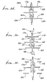
- Figs. 1 a --1 f show in diagrammatic form the positions of both wire severing and sheathing stripping blades, during various steps in a wire processing procedure or method.
- the "wire" 10 (meant to also refer to cable) has a metal core 11 a and a tubular sheathing 11 b about the core.
- the wire is shown extending axially longitudinally in Figs. 1 a --1 f , the axis being located at 12 .
- First cutter means is provided to include, or may be considered to include, multiple blades. See for example the two wire-cutting blades 13 a and 13 b of a first set, located or carried for movement laterally toward and away from the wire axis 12 .
- Second and third cutter means are also provided, for sheathing stripping, and each may be considered to include multiple blades located for movement toward and away from the axis 12 . See for example the second set of two blades 16 a and 16 b , and the third set of two blades 17 a and 17 b .
- Blades 16 a and 16 b are located, or considered to be, controllably simultaneously displaced, as by drive 18 , (or by separate or multiple drives) laterally oppositely, toward one another (see arrows 19 a and 19 b in Fig. 1 d ), the drive also operable to retract the blades 16 a and 16 b away from one another.
- the blades 17 a and 17 b are located, or carried to be, controllably displaced simultaneously laterally oppositely toward one another (see arrows 20 a and 20 b in Fig. 1 d ), and drive 18 may be used for this purpose.
- blades 16 a and 16 b may be displaced toward one another at the same time and to the same extent as blades 17 a and 17 b are displaced toward another, as is clear from Fig. 1 d .
- the latter shows that the blades 16 a and 16 b , and 17 a and 17 b , do not sever the wire but may closely approach the wire, while cutting into sheathing 11 for stripping purposes.
- Figs. 9-11 show the blades 16 a and 16 b to have V-shape, as do wire severing blades 13 a and 13 b , and blades 17 a and 17 b .
- Similar functioning of blade edges 17 a ' and 17 a '' , and 17 b ' and 17 b '' also takes place, as in Fig. 1 d .
- Fig. 1 a shows displacement of the wire axially endwise and longitudinally, as by a conveyor means 21 a to the first position as shown.
- Fig. 1 b shows the step of severing the wire thereby to form wire forward and rearward sections 10 a and 10 b , the blades 13 a and 13 b being advanced laterally to accomplish complete severing at locus 22 , as shown.
- wire forward section 10 a has a rearward end portion 10 aa
- the wire rearward section 10 b has a forward end portion 10 bb .
- Fig. 1 c shows the step of controllably separating the two sections 10 a and 10 b axially endwise oppositely, as to the positions shown, in which the end portions 10 aa and 10 bb are spaced from the closed-together blades 13 a and 13 b .
- Guides 24 and 25 provided between the blade sets, serve to accurately guide the wire and the sections 10 a and 10 b during the cutting and severing operation, as is clear from Figs. 1 a --1 f . Note the tapered entrances 24 a and 25 a to the guides to receive and center the forwardly advanced wire.
- Wire drives 21 a and 21 b are controllably operated to engage and separate the two sections 10 a and 10 b , as indicated in Figs. 1 a and 1 c .
- Fig. 1 d shows a sub-step included within the step of stripping sheathing from the forward section rearward portion and from the rearward section forward portion, thereby to expose wire ends at the portions.
- blades 16 a and 16 b are simultaneously advanced laterally oppositely, as to blade edge positions described above, as respects Fig. 10 a , and as blades 17 a and 17 b are also simultaneously advanced laterally oppositely (as to the same extent if such stripping is to be equal for each wire section).
- blades 13 a and 13 b now extend in laterally overlapping condition, due to operation of drives 15 and 18 as one, i.e., equal rightward lateral displacement for blades 13 a , 16 a and 17 a , and equal leftward lateral displacement for blades 13 b , 16 b and 17 b ; however, they may be separately driven so as not to extend in such relation, as shown.
- Blades 13 a , 16 a and 17 a may be connected together to move rightwardly to equal extent; and blades 13 b , 16 b and 17 b may also be connected together to move leftwardly as one, for extreme simplicity.
- Fig. 1 e shows operation of the wire drives to further endwise separate the wire sections 10 a and 10 b so as to pull or strip two sheathing end portions 11 b ' and 11 b '' from the wire sections 10 a and 10 b , thereby to expose the wire core end portions 11 a ' and 11 a '' .
- the stripped sheathing end portions 11 b ' and 11 b '' , or slugs are allowed to drop out from between the pairs of guides 24 and 25 which may be split, as shown, to provide slug drop-out openings, and may be movable to facilitate such drop out.
- Fig. 1 f shows all blades laterally retracted and the wire rearward section 10 b fully advanced into position corresponding to Fig. 1 a position for controlled length endwise positioning to be processed, as in Figs. 1 b --1 e , to provide an exposed core end at its opposite end.
- controlled length wires or cables, with exposed core lengths at each end of each wire, is efficiently and rapidly and controllably provided. See master control 35 to control all the driving, as described, and to be described.
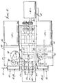
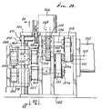
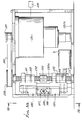
- a frame is provided, as at 40-44 and 44 a , to mount two conveyors 45 and 46 , which may be considered as included within the wire drives 30 and 31 , as mentioned.
- Such conveyors may include two rearwardly positioned endless belts 47 and 48 , and two forwardly positioned endless belts 49 and 50 .
- the belts provide stretches, as at 47' and 48' , which are adapted to sidewise flatly grip the wire 10 (and specifically the wire rearward section 10 b ) for endwise advancement and retraction, as during separation of the sections 10 a and 10 b in Fig. 1 c ; and stretches 49' and 50' are adapted to sidewise grip the wire 10 (and specifically the wire forward section 10 a ) for endwise advancement and retraction.
- the belts 47 and 48 are driven to advance or retract the wire section 10 a , as from a drive motor 52 (see Fig. 4).
- the output shaft 53 of the motor drives belt 54 , as via a pulley 55 , and belt 54 drives shafts 56 and 57 .
- Shaft 56 drives another shaft 58 , through gearing 59 and 60 , to drive shaft 58 and upper conveyor belt 47 clockwise; whereas, lower shaft 57 and lower belt 48 are driven counterclockwise in Fig. 2. This drives the wire forwardly; whereas, when motor 52 is reversed, the wire is driven rearwardly. Additional axles or shafts for the conveyor belts 47 and 48 appear at 58 a and 57 a .
- Fig. 2 shows conveyor rotors 60 and 61 , and 62 and 63 . These carry the belts 47 and 48 . Axles 58 a and 57 a are driven by drive belts 64 and 65 extending between pulleys on the shafts 58 and 58 a , and 57 and 57 a , as shown. Accordingly, when the belt stretches 47' and 48' are closed against opposite sides of the wire 10 , and the motor 52 is operating, the wire is displaced endwise.
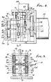
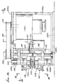
- Means is provided to move the conveyor belt stretches 47' and 48' toward one another to clutch the wire, and away from one another to de-clutch the wire. See for example in Figs. 3-5 the motor or drive 66 carried by a frame part 67 , to rotate a vertical screw shaft 68 , as via motor output shaft 69 , pulley 70 , belt 71 , and pulley 72 on the screw shaft 68 .
- the screw shaft has screw thread engagement at 73 and 74 with frame members 75 and 76 .
- Frame member 76 supports the ends of shafts 58 and 58 a , via member extension 76 a , as at 58' and 58 a ' ; whereas, frame member 75 supports the ends of shafts 57 and 57 a , via member extension 75 a , as at 57' and 57 a ' .
- Screw threading interfit at 74 is oppositely "handed" relative to threading interfit at 73 , so that, when shaft 68 is rotated in one direction about its axis, the frame members 75 and 76 are displaced toward one another, whereby conveyor stretches 47' and 48' may clamp the wire; and when the shaft 68 is rotated in the opposite direction about its axis, the members 75 and 76 are displaced away from each other, and the wire is de-clutched.
- the bearing supports at 78 and 79 for shafts 58 and 57 are made loose enough to accommodate such up/down movement of those shafts at the conveyor belt drive locations. Note also couplings at 110 and 111 .
- Tension springs 90 and 91 are provided (see Fig. 5) between fixed frame structure 92 and shoulders 76 a ' on 76 a , to yieldably urge the structures 76 and 76 a , and the belt stretch 47' downwardly; and similarly, tension springs 93 and 94 are provided between fixed frame structure 95 and shoulder 75 a ' on 75 to yieldably urge the structure 75 and 75 a , and the belt stretch 48' , upwardly. This provides clearance "take-up" for better control of wire gripping or clamping.
- the forward conveyor unit 46 embodies conveyor belt drive and up/down movement, the same as described in connection with unit 45 in Figs. 3-5.
- the drive motor 52 a for driving the belt stretches 49' and 50' forwardly and reversely, is seen in Fig. 3, as is the motor 66 a to control belt clamping of the forward wire section.
- Mechanism between the motors 52 a and 66 a , and the respective forward conveyor belts 49 and 50 is the same as above described mechanism between motors 52 and 66 , and the respective rearward conveyor 47 and 48 ; however, the motors 52 and 51 a are typically operated simultaneously, either to drive the wire or wire sections forwardly, as in Figs. 1 a and 1 f , or to drive the wire sections endwise oppositely, as in Figs. 1 c and 1 e .
- a master control to control all drives, in a pre-programmed manner, is seen at 125 .
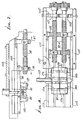
- the wire severing blades 13 a and 13 b are fully laterally retracted, as are the wire sheathing stripping blades 16 a and 16 b .
- Blades 17 a and 17 b are in axial alignment with blades 16 a and 16 b and are not shown. Note V-angled blade edges 13 a ' and 13 a '' , and blade edges 13 b ' and 13 b '' .
- the blades 13 a , 16 a and 17 a at one side of the wire 10 are interconnected by axially extending carrier rod 80 ; and the blades 13 b , 16 b and 17 b at the opposite ends of the wire are interconnected by axially extending carrier rod 81 , laterally spaced from rod 80 .
- Rods 80 and 81 are relatively movable laterally toward one another to effect wire severing, as by blades 13 a and 13 b (see Fig. 9 and also Fig. 1 b ).
- Rods 80 and 81 are further laterally movable toward one another to effect penetration of the blade edges 16 a ' and 16 a '' , and 16 b ' and 16 b '' , into the sheathing (as in Figs. 10 and 10 a ), and as also seen in Fig. 1 d . Thereafter, the wire forward and rearward sections 10 a and 10 b are separated, as in Fig. 1 e , to endwise strip the slugs 10 aa and 10 bb off the wire cores, as also seen in Fig. 11. Dropping of the slug is also seen in Fig. 11, as is lowering of a wire guide lower sector B of guide 11 b '' , to release the slug. The upper guide sector is shown at A.
- a drive 130 is operable to lower and raise sector B.
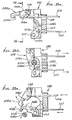
- a laterally extending lead screw 90 is rotatable by a drive motor 91 , carried by frame part 83 . See connecting shaft 93 .
- nuts 94 and 95 on the screw threads travel axially oppositely (see arrows 96 and 97 ) to move rod 80 to the right and rod 81 to the left, as in Figs. 9 and 10.
- a pair of parallel lead screws 90 may be utilized for these purposes, as seen in Fig. 8, each driven by the motor 91 , with one lead screw associated with blades 16 a and 16 b , and the other associated with blades 17 a and 17 b . Balanced force transmission to the two sets of blades is thereby effected. See also frame elements 110-116 supporting the structure, as indicated. Bearings appear at 117 and 118 . An additional tubular wire guide is seen at 119 .
- Figs. 13 a --13 b the elements which correspond to those in Figs. 1a)--1f) bear the same numerals.
- Fig. 13 a corresponds to Fig. 1 c ; and
- Fig. 13 b corresponds to Fig. 1 e .
- the wire sections 10 a and 10 b are displaced, endwise axially oppositely, to controlled extent, as by drives 21 a and 21 b , under computer control, so as to control such displacement. See for example the displacements d1 .
- the blades 16 a and 16 b , and 17 a and 17 b penetrate into the sheathing; and wire sections 10 a and 10 b are displaced axially endwise oppositely (see arrows 200 and 201 ), to controlled extents h1 and h2 , as by the computer-controlled drives 21 a and 21 b , to relatively displace the insulation slugs to positions shown in Figs. 13 b , 13 c , and 13 d , wherein the slugs protectively overhang the cut ends 11 aa and 11 bb of wire core. This protects against fraying of ends of wire clustered strands, as seen at 11 c in Figs. 13 b --13 d .
- the blades are then retracted, to leave the wire sections and slugs, as seen in Fig. 13 c , the final product being seen in Fig. 13 d .
- the slugs are held in position on the core by friction, and may be pulled off at time of wire use.
- the cutters can be oriented to move horizontally, or vertically, or in other directions.
- Figs. 14-16 the blade arrangements and operations are the same as in Figs. 1 a --1 f , and 13 a and 13 b , the blades moving vertically.
- the blade actuators 180 and 181 carrying rods 80 and 81 see in Figs. 9-12.
- Such actuators are also seen in Figs. 3 and 8.
- Drives for the actuators are schematically indicated at 15' in Fig. 16.
- Wire 10 passing endwise through the blade region is guided by guides 124 and 125 , corresponding to guides 24 and 25 in Figs. 1 a --1 f .
- a part of each guide is movable away from a slug of insulation formed by closing of the blades, as described above.
- the two guides have parts 124 a and 125 a that are swingable away from the wire axis (see the broken line position 124 a ' of guide part 124 a in Fig. 14 for example). Guide parts that do not move away from the wire are indicated at 124 b and 125 b .
- a pin 127 pivotally attaches each part 124 a and 125 a to frame structure 128 .
- a reciprocating drive swings the part 124 a to position 124 a ' and back, under the control of master control 35 .
- That drive for example, includes a motor 130 , and linkage means, including interconnected links 131-134 , operatively connected between the motor shaft 135'' and the part 124 a .
- a corresponding motor 130 a and links 131 a --134 a are connected to part 125 a to pivot same.
- Guide parts 124 a and 125 a have concave arcuate wire guide surfaces, as at 124 aa .
- a pusher and drive therefor for displacing the pusher to bodily push against the side of the severed length of sheathing (slug) for ejecting same in operative conjunction with moving (pivoting) of the part 124 a .
- a pusher and drive therefor for displacing the pusher to bodily push against the side of the severed length of sheathing (slug) for ejecting same in operative conjunction with moving (pivoting) of the part 124 a . See for example the reciprocating plunger 135 , and its drive, connected to the same drive as used to pivot the part 124 a .
- the plunger 135 is connected to the linkage 133 and 132 . See also Fig. 17 showing plunger 135 connected at 132 a to link 132 .
- the nose 135' of the plunger is shown pushing the wire slug 10 aa to the left.
- a similar pusher is operated in conjunction with pivoting of wire guide part 125 a .
- a wire guide opening appears at 140 in Fig. 14.
- Motors 130 and 130 a operate in one direction (rotate 180°), and then operate in reverse (-180°), to drive the pushers and swingable guide parts.
- first cutter means includes the two wire-cutting blades 213 a and 213 b of a first set, located or carried for movement laterally toward and away from the wire axis 212 .
- Second cutter means includes blades 216 a and 216 b located for movement toward and away from axis 212 , for stripping sheathing from the wire at one axial side of blades 213 a and 213 b ; the third cutter means includes blades 217 a and 217 b movable toward and away from axis 212 , for stripping sheathing from the wire at the opposite axial side of blades 213 a an 213 b .
- Blades 216 a and 216 b , and blades 217 a and 217 b do not sever the wire, but closely approach the wire while cutting into sheathing 211 , for stripping purposes. See Figs. 18 d and 18 e .
- a drive 218 is connected at 218 a to blades 213 a , 216 a , and 217 a , to move them laterally and simultaneously toward and away from the wire; and a drive 219 is connected at 219 a to blades 213 b , 216 b , and 217 b , to move them laterally and simultaneously toward and away from the wire.
- the blades are shown as thin, flat, steel sheets, formed to have dovetailed tongue ends at 213 a 1 , 216 a 1 , 217 a 1 , and at 213 b 1 , 216 b 1 , and 217 b 1 .
- dovetailed ends are receivable in and gripped by dovetailed groove holders schematically indicated at 229 and 230 , assuring ease of replacement of the blades, while also assuring positive gripping of the blades and their proper alignment.
- Such holders 229 and 230 may be considered as parts of the drives 218 a and 219 a , respectively.
- the blades themselves have V-shaped cutting edges arranged in pairs in opposed relation.
- blades 213 a and 213 b have opposed V-shaped edges at 213 a 2 and 213 b 2 , which sidewardly slidably overlap completely during wire severing (see Fig. 18 b );
- blades 216 a and 216 b have opposed V-shaped edges at 216 a 2 and 216 b 2 , which sidewardly slidably overlap to limited extent during sheathing stripping (see Figs.
- blades 217 a and 217 b have opposed V-shaped edges at 217 a 2 and 217 b 2 , which sidewardly overlap to limited extent during sheathing stripping (see Figs. 18 d and 18 e ).
- Such opposed V-shapes of the cutting edges assure complete severing of the sheathing.
- Fig. 18 a shows wire 11 axially endwise advancement of the wire to first position.
- Fig. 18 b shows the step of severing the wire, thereby to form wire forward and rearward sections 210 a and 210 b , the blades 213 a and 213 b being advanced laterally toward the wire, from opposite sides, to accomplish severing.
- wire forward section 210 a has a rearward end portion 210 aa ; the wire rearward section 210 b has a forward end portion 210 bb .
- Fig. 18 c shows the step of controllably separating the two sections 210 a and 210 b axially endwise oppositely, as to the positions shown, in which the end portions 210 aa and 210 bb are spaced from the close-together blades 213 a and 213 b .
- Guides provided between the blade sets serve to accurately guide the wire and the sections 210 a and 210 b during the cutting and severing operation.
- Such guides are seen for example in 524 and 525 in Figs. 34, 35 a , 35 b , 35 c , 37, 38, and 39. Note the tapered entrances 524 a and 525 a to the guides to receive and center the forwardly advanced wire.
- Wire drives are controllably operated to axially advance and separate the two wire sections 210 a and 210 b , as indicated in Figs. 18 a and 18 c .
- Fig. 18 d shows a sub-step included within the step of stripping sheathing from the forward section rearward portion and from the rearward section forward portion, thereby to expose wire ends at the portions. Note that blades 216 a and 216 b are simultaneously advanced laterally oppositely, as blades 217 a and 217 b are also simultaneously advanced laterally oppositely (and to the same extent if such stripping is to be equal for each wire section).
- blades 213 a and 213 b now extend in laterally overlapping condition, due to operation of blade drives 218 and 219 as one, i.e., equal downward lateral displacement for blades 213 a , 216 b , and 217 b , and equal upward lateral displacement for blades 213 b , 216 b , and 217 b ; however, they may be separately driven so as not to extend in such relation, as shown.
- Blades 213 a , 216 a , and 217 a may be connected together to move downwardly to equal extent; and blades 213 b , 216 b , and 217 b are connected together to move upwardly as one, for extreme simplicity.
- Fig. 18 e shows operation of the wire drives 230 and 231 , to further endwise separate the wire section 210 a and 210 b , so as to pull or strip two sheathing end portions 210 a ' and 210 b ' from the wire sections 210 a and 210 b , thereby to expose the wire core end portions 211 a ' and 211 b ' .
- the stripped sheathing end portions or slugs 210 a ' and 210 b ' are rejected, as will be seen, from between the pairs of guides 524 and 525 , which may be shaped to provide for slug sideward de-confinement and ejection, as will be described further.
- Fig. 18 f shows all blades laterally retracted and the wire rearward section 210 b fully advanced into position corresponding to Fig. 1 a position, for controlled length, endwise positioning to be processed, as in Figs. 18 b --18 e , to provide an exposed core end at its opposite end.
- controlled length wires or cables
- exposed core lengths at each end of each wire are efficiently and rapidly, and controllably provided. See master control 325 to control all the drives, as described, and to be described.
- a frame is provided as at 240-244 and 244 a , to mount conveyors, as represented by roller groups 245 and 246 . These may be regarded as included within the wire drives 230 and 231 , as mentioned.
- Such conveyors may include two rearwardly positioned endless belts 247 and 248 ; and two forwardly positioned endless belts 249 and 250 .
- the belts 247 and 248 provide stretches, as at 247' and 248' , which are adapted to sidewise flatly grip the wire or cable 210 (and specifically section 210 b ) for endwise advancement and retraction, as during separation of the wire sections 210 a and 210 b in Fig. 18 c .
- stretches 249' and 250' provided by belts 249 and 250 , are adapted to sidewise grip the wire or cable 210 (and specifically the forward wire section 210 a ) for endwise advancement and retraction.
- Belts 249 and 250 are driven to advance or retract the wire section 210 a , as from a drive motor 252 (see Fig. 20).
- the output shaft 253 of the motor drives belt 254 , as via a sprocket 255 , and belt 254 drives shaft 256 .
- Sprocket 255 also drives a belt 254 a , which drives a shaft 257 via a pulley 257 a .
- Shaft 256 drives another shaft 258 , as via angular reversing gearing 259 and 260 , in order to drive shaft 258 , shaft 258' , and upper conveyor belt 249 counterclockwise; whereas, lower shaft 257 , shaft 257' , and lower conveyor belt 250 , are driven clockwise, in Fig. 19.
- the conveyor belts drive the wire endwise in one axial direction; whereas, when the motor 252 is reversed, the wire is driven endwise in the opposite axial direction.
- Fig. 22 shows additional coupling 410 between offset shafts 258 and 258' , and coupling 411 between offset shafts 257 and 257' .
- Such couplings include the timing belts 412 and 413 , and timing gears 414 and 415 , and 416 and 417 , as shown.
- Shafts 257 and 258 are typically not pivotable (to swing bodily); whereas, shafts 257' and 258' may pivot, in effect, as their support plates 418 and 419 are moved up and down as lead screw 268 rotates. See the horizontal lost-motion, connection-type, bearing supports 418' and 419' for those shafts in Fig. 22. This allows the conveyor belt stretches 249' and 250' to be flatly and adjustably engaged and disengaged with the wire or cable 210 , as seen in Fig. 22. See also Fig. 21.
- Fig. 19 also shows conveyor rotors 260 and 261 , and 262 and 263 . These carry the belts 249 and 250 .
- Axle 258'' for rotor 261 is suitably driven by axle 258' , as via a belt and pulleys; and axle 257'' is suitably driven by axle 257' , as via a belt and pulleys (see in Fig. 2 drive belts 14 and 15 , etc.). Accordingly, when the belt stretches 249' and 250' are closed against the opposite sides of the wire 210 b , and the motor 252 is operating, the wire is displaced endwise. Similar drives for conveyors 247 and 248 are provided, as shown.
- Means is provided to move the conveyor belt stretches 249' and 250' relatively toward one another to clutch the wire, and away from one another to de-clutch the wire. See for example in Figs. 19-21 the motor or drive 266 carried by a frame part 241 to rotate a vertical lead screw shaft 268 , as via motor output shaft 269 , sprocket 270 , timing belt 271 , and sprocket 272 on shaft 268 .
- the screw shaft has screw thread engagement at 273 and 274 , with nut members 275 and 276 associated relatively with plates 418 and 419 .
- Plate 418 supports the end of shaft 258' , for up and down movement; and plate 419 supports the end of shaft 257' for up and down movement. Support of such shaft ends is via the lost-motion connections described above at 418' and 419' .
- Screw threaded connection to the nut 275 is oppositely "handed" relative to threaded connection to nut 276 , so that, when shaft 268 is rotated in one direction about its axis, the nuts 275 and 276 , and plates 418 and 419 (and shafts 257' and 258' ) are yieldably displaced toward one another, whereby conveyor stretches 249' and 250' may clamp the wire; and when the shaft 268 is rotated in the opposite direction about its axis, the nuts and plates are yieldably displaced away from one another, and the wire is de-clutched. Nuts 275 and 276 are confined in vertical slots 275' and 276' in plates 418 and 419 , allowing relative movement between the nuts and plates.
- Compression springs 290 and 291 are provided (see Figs. 22) between the nuts and the supports 418 and 419 to yieldably urge the supports 418 and 419 toward one another, in response to lead screw 268 rotation in one direction, to provide clearance "take-up" for better control of wire gripping, especially for smaller diameter wires. Those springs engage shoulders 418 a and 419 a , as shown. Additional compression springs 290 a and 291 a are provided between the nuts and shoulder 418 b and 419 b to yieldably urge the plates and shafts apart as the lead screw rotates in the opposite angular direction. Similar structures are associated with the conveyors 247 and 248 , and bearing the same identifying numbers.
- the rearward conveyor unit 245 embodies conveyor belt drive, and up/down movement, the same as described in connection with unit 246 in Figs. 19-22.
- the drive motor 252 a (not shown) for driving the belt stretches 247' and 248' forwardly and reversely is similar to motor 252 , and corresponds to motor 66 in Fig. 2.
- the motor to control belt clamping of the wire is seen at 266 a in Fig. 19.
- Mechanism operation between such rearward motors and the respective belts 247 and 248 is the same as mechanism between motors 266 and 252 , the belts 249 and 250 .
- the forward and rearward belt motors 252 and 252 a are typically operated simultaneously, either to drive the wire or wire sections forwardly, as in Figs. 18 a and 18 f , or to drive the wire sections endwise oppositely, as in Figs. 18 c and 18 e .
- a master control to control all drives in a predetermined manner is seen at 325 in Fig
- blades 213 a , 216 a , and 217 a at the upper side of the wire are interconnected, as by the laterally extending blade holder 280 ; and the blades 213 b , 216 b , and 217 b at the lower side of the wire are interconnected by laterally extending blade holder 281 , vertically spaced from holder 280 .
- Those holders are vertically movable toward one another to effect wire severing, as by V edges of blades 213 a and 213 b .
- Those holders are further movable toward one another to effect penetration into the sheathing of the edges of blades 216 a , 216 b , and 217 a and 217 b .
- the wire forward and rearward sections 210 b and 210 a are separated, axially, as in Figs. 18 e , to endwise strip the insulation tubular slugs off the wire cores, a typical slug 210 aa being ejected, as in Fig. 35 c . That view also shows dropping of the ejected slug, away from the mechanism.
- a vertical lead screw 290 is rotatable by a drive motor 291 , carried by drive structure 292 a --292 c .
- Screw 290 bearings are indicated at 290 a .
- Belt and pulley elements 501-503 connect motor 291 to the screw.
- nuts 294 and 295 on the screw threads travel axially oppositely along the screw to move blade holder 280 down and holder 281 upwardly. See sliding blocks 298 and 299 connecting holder 280 with nut 294 , and holder 281 with nut 295 .
- Block bearings 298 a and 299 a slide along guide rods 310 , carried by frame structure 292 a and 292 c .
- the blade holder 280 is held in interengagement at 311 with the block 298 by a clamp 312 , which engages the front side of the holder at 313 .
- a fastener 314 attaches the clamp to the block 298 .
- Dovetailed tongue end 216 a ' of blade 216 a has one angled edge surface 216 a 1' , engaged with correspondingly dovetailed surface 280 a 1 , for retention.
- a retainer in the form of a shaft 420 has an interior flat surface 420 a rotatable into corresponding engagement with the oppositely angled surface 216 a 2 ' of the blade, thereby to retain and locate the blade, vertically. Set screws 420 a keep shaft 420 from rotating.
- Figs. 31 and 33 also show the dovetailed portions of three blades fitting in position, as in vertical slots 415-417 , defined by a blade clamp bar or bars 419 .
- Screws 426 attach bar or bars 419 to blade holder 280 .
- Magnets 427 carried by the block 298 , are positioned to magnetically attract vertical edge portions of the blades (as at 216 d in Fig. 31), to keep the three blades positioned as they are initially received in slots 415-417 , and prior to rotation of shaft 420 , as described, into Fig. 31 position, to positively hold the blade.
- Shaft 420 has end extents 420 c and 420 d carried in bearing openings 431 and 432 in holder 280 parts 280 f and 280 g . See also manually rotatable handle 433 of shaft 420 . Reverse rotation of shaft 420 allows quick, manual, frontward reversal, and replacement of the blades.
- Figs. 26-29, 34, 35 a --35 c , and 36 structure is shown that serves to guide the wire during its axial movement relative to the blades, and to facilitate removal of a severed slug or slugs or insulation or sheathing material.
- Fig. 34 wire passing in horizontal direction 500 through the blade region is guided by two guides generally indicated at 524 and 525 .
- a part of each guide is movable away from a slug of insulation formed by closing of the blades, and wire retraction, as described above.
- the two guides have parts 524 a and 525 a that are swingable laterally and upwardly, away from the wire axis, as better seen in Fig. 35 c .
- Guide part 524 a is pivotally connected at 550 to blade holder 280 , to swing about horizontal axis 550 a extending parallel to the direction of wire advancement.
- Part 524 a may be considered as a trap door, in the sense that when swung to Figs. 35 c and 35 a positions, it has swung away from the side of the wire slug, leaving the slug free for ejection.
- Part 524 a forms a semi-circular guide surface 524 a ' that guides the wire 210 when the part 524 a is in closed position, as seen in Fig. 35 b .
- Part 525 a of guide 525 has construction and operation the same as described for part 524 a .
- the guides 524 and 525 also incorporate parts 524 b and 525 b which act as pushers, to bodily push against the sides of the severed lengths (slugs) of sheathing, for ejecting same laterally, in cooperative conjunction with pivoting movement of parts 524 a and 525 a , as described.
- part 524 b is pivotally connected at 553 to blade holder 280 , to swing about horizontal axis 553 a , extending parallel to the direction of wire advancement.
- Part 524 b may be considered as a pusher or ejector, in the sense that, as seen in Fig. 35 c , it bodily ejects or displaces the wire slug 211 b ' laterally and downwardly, positively and assuredly away from the mechanism, immediately after the trap door part 524 a opens (swings to the position seen in Fig. 35 c ).
- Part 524 b has a semi-circular guide surface 524 b ' that guides the wire 210 when parts 524 a and 524 b are in closed positions, as seen in Fig. 35 b .
- Part 525 b of guide 525 has a construction and operation the same as described for part 524 a .
- Parts 525 a and 524 b lie between blades 216 a and 216 b , and blades 213 a and 213 b ; and parts 525 a and 525 b lie between blades 213 a and 213 b , and blades 217 a and 217 b , as is seen from Fig. 34.
- the trap door parts 524 a and 524 b , and pusher parts 524 b and 525 b have associated reciprocating drives, to open and close them in timed relation, as described. See for example in Figs. 35 a --35 c the links 556 and 557 , respectively, pivotally connected with parts 524 a and 524 b , as at 556 a and 557 a , the links passing through guide openings 558 and 559 in the blade holder structure.
- Figs. 28 and 29 show link 556 driven by a motor 560 , as via crank arm 561 connected to the motor shaft 560 a , link 562 extending from 561 to a slider 563 , and that slider also connected to link 557 .
- Frame part 565 carries the motor.
- Link 557 is also driven by motor 560 , as via crank arm 561 , link 558 extending away from 561 to a slider 559' , and that slider connected to link 557 .
- Guide posts for the sliders appear at 563 a and 559 a . See also Fig. 29.
- Fig. 34 shows corresponding actuating link 556' for the trap door part 524 a , and link 557' for the pusher part 524 b , these operated in the same way as links 556 and 557 .
- a sensor is provided to sense arrival of the wire endwise in proximity to the trap door parts and to the pusher elements, as described. See sensor 569 in Fig. 19.
- Figs. 34 and 40 show a tapered, tubular guide 570 at which the advancing wire end arrives after traversing the blade region.
- the senor takes the form of a very lightweight, swingable door 571 extending across the wire path, and hinged at 572 to swing forwardly upwardly in response to engagement by the traveling wire 210 b forward end 210 b ' .
- Such swinging movement is sensed, as by an optical sensor.
- the latter typically includes a light beam (electromagnetic wave) source 574 producing a beam sensed at 575 , such sensing occurring for example when the beam is interrupted by door swinging. This serves to notify the operator that the wire end has arrived at the sensor position, i.e., the wire has traversed the blade zone.
- the sensor at 575 in Fig. 42 may control drive 325 , so as to stop the advancement of the wire conveyors 249 and 250 . See circuit connections 576 and 577 .
- An alternate position for the door is shown at 571' , in closer proximity to the conveyor means 249 and 250 .
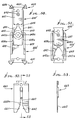
- the multiple blade structures shown are adapted to use in apparatus of the type described above for processing wire to cut the wire into sections and to strip sheathing from the sections to expose section wire ends, the apparatus including conveyor means for displacing the wire axially endwise.
- upper and lower supports are provided at 600 and 601 for supporting multiple blade structures.
- the latter includes at least two of such structures, seen at 602 and 603 , that mutually interfit as they are moved (by supports 600 and 601 for example) relatively oppositely toward and away from the axis 604 defined by the wire or cable 605 to be cut, in directions generally normal to that axis. See arrows 606 and 607 .
- At least one of the structures ( 603 for example) defines first shoulders 608 a and 609 a on ribs 608 and 609 , respectively, such shoulders being elongated in directions 606 and 607 , and being laterally spaced and opposed, to form intermediate space 610 between which the other of the two structures ( 601 for example) or a portion thereof extends or relatively moves or slides, as during such relative movement.
- Shoulders 608 a and 609 a may, in this regard, act as guide shoulders on blade-strengthening ribs 608 and 609 ; such structures also enhancing correct positioning for gripping and cutting of the cable by the upper structure (see Fig. 45), correct alignment of the blade structures normal to axis 604 , correct closing of the blade structures, as seen in Fig. 46, gripping by lower support structure 601 , as well as providing other benefits.
- Gripping occurs at dovetail shoulders 610 and 611 on base portion 612 of the structure 603 , of a thickness the same as that of ribs 608 and 609 , and thicker than reduced thickness of the reduced blade plate 613 of 603 , supported and stiffened by 608 , 609 , and 612 .
- edge 614 of blade plate 603 which has portions 614 a and 614 b extending oppositely from a C-shape, medial or bridging cutting edge 614 c that receives one half the wire metallic core 616 (see Fig. 44) without cutting into it, as during insulation stripping.
- edge 614 c cuts one half the insulation or sheathing 636 .
- Elements 610 , 608 , 609 , and 612 may be integral or of one piece (if metal).
- the other or second blade structure defines second shoulders 617 a and 618 a on ribs 617 and 618 , such shoulders also being elongated in directions 606 and 607 , and being laterally spaced and opposed to align ribs 617 and 618 with ribs 608 and 609 , respectively, during relative structure movement. See aligned ribs in Fig. 46 at time of blade structure maximum closing, shoulder 617 a aligning with shoulder 608 a , and shoulder 618 a aligning with shoulder 609 a .
- the ribs 617 and 618 are provided on a blade holder 620 , which is part of 602 and is downwardly U-shaped, as shown, there being a base 621 integral with 617 and 618 .
- An upper blade plate 622 is riveted at 623 and 624 to the flat section 625 of the holder, section 625 being integral with 617 , 618 , and 621 , i.e., 622 fits between 617 a and 618 a .
- the upper blade plate is stiffened and strengthened by holder 620 , to provide support for the downwardly extending legs 622 a and 622 b of 622 that fit closely between and are guided by rib shoulders 608 a and 609 a on 603 , during closing together of the two blade structures, as seen in Fig. 46.
- Upwardly tapering wire guide edges 630 and 631 are provided on the two legs, and they terminate at a C-shaped medial or bridging cutting edge 632 that closes toward corresponding edge 614 c to form a circular or oval-shaped opening to receive the uncut wire core during sheathing cutting and stripping.
- Edge 632 cuts through the remaining one half of the sheathing. See Figs. 46 a and 46 b . That oval opening is of minimum diameter greater than wire core diameter, to allow slippage of the core through that opening as during stripping, to remove the sheathing slug, seen at 636 a in Fig. 44, off the wire core.
- the second shoulders are defined by opposite edges 640 and 641 of the legs 642 and 643 of upper blade plate 644 ; and shoulders 640 and 641 fit or slide adjacent rib shoulders 608 a and 609 a on the lower blade structure 603' .
- Tapered wire guide edges 642 a and 643 a are formed on legs 642 and 643 , and urges the wire toward cutting position, as seen in Fig. 51.
- the upper blade structure 602' also includes strengthening holder 647 riveted at 648 to the upper blade plate 644 , and forming dovetailed retention grip shoulders or edges 654 and 655 , with the advantages of shoulders 650 and 651 described above. Gripping of the dovetailed shoulders, in support 600 and 601 , proceeds as described in Figs. 31-33 above.
- Retainers 670 and 671 in Fig. 43 correspond to retainer 420 in Figs. 31-33.
- Handles 673 and 674 enable rotation of 670 and 671 to quickly grip and release the blade structures.
- Set screws 680 and 681 are adjustable to lock the rotary retainers in position.
- Fig. 52 shows a further modification of an upper blade structure, with C-shaped edge 660 in a medial slot 660 a , and above tapered wire guide edges 661 and 662 on the upper blade structure plate 663 , otherwise similar to 641 .
- a medial blade set 690 includes upper and lower blades 691 and 692 to cut completely through the wire when the supports are closed toward one another in the manner seen in Fig. 18 e or in Fig. 10.
- the apparatus provides a first set of multiple of the blade structures at one side of the axis, and a second set of multiple of the blade structures at the opposite side of the axis, the retainer means including a first retainer carried by the support means at one side of the axis for rotary advancement to hold the multiple blade structures of the first set in the fixed position, and for rotary retractions to allow release of the blade structures of the first set.
- the retainer means includes a second retainer carried by the support means at the opposite side of the axis for rotary advancement to hold the multiple blade structures of the second set in the fixed position and for rotary retention to allow release of the multiple blade structures of the second set.
- the multiple blade structure of each set includes two or three of the pairs of blade structures, and typically two, as seen in Fig. 43, with an additional wire severing blade pair intermediate the two stripping pairs of blade structures, as shown.
- Drive elements 290 and 290 a are coupled together at 500 and oppositely screw threaded as shown to drive the blade holders 280 and 281 endwise oppositely, i.e., toward one another and away from one another, depending upon the direction of rotation of 290 and 290 a .
- Elements 501 and 502 on 290 and 290 a engage holders 280 and 281 at surface interengagement loci 503 and 504 , to guide holders 280 and 281 accurately, as they travel endwise oppositely.
- Blade structures including at least two such structures 507 and 508 that mutually move adjacent one another (as for example slidably interfit at plane 506 ) and such two structures move relatively oppositely, toward and away from the axis 515 of the wire or cable 580 being processed.
- Blade structure cutting edges are indicated at 509 and 510 on structure 507 , and at 511 and 512 on structure 508 .
- Fig. 54 a shows the blade structures 507 and 508 in "open" position, i.e., with all cutting edges spaced from the wire 580 being processed;
- Fig. 54(b) shows the blade structures 507 and 508 moved in directions 520 and 521 into wire cutting positions with cutting edges 510 and 511 overlapping at opposite sides of axis 515 ;
- Fig. 54(c) shows the blade structures 507 and 508 moved in directions 522 and 523 into wire stripping positions, with cutting edges 509 and 512 partially penetrating the wire or cable, i.e., to cut into the wire insulation 580 a sufficiently to strip the insulation from wire core 580 b when the wire is moved endwise, as described, in detail above.
- each of the structures extend at opposite sides of the wire axis; that only two such structures 507 and 508 are employed, each defining a single plane; that the two structure planes extend in parallel relation; that the structures remain in sidewardly overlapping relation during their movements, as is clear from Fig. 54; that cutting blade 510 is on one structure 507 , and cutting blade 511 is on the other structure 508 ; and that stripping blade 509 is on the one structure 507 and stripping blade 512 is on the other structure 508 . Consequently, the blade structures and their functioning are very simple, i.e., much simpler than in Figs. 1-53, since only two moving blade structures are needed.
- each of the two structures has first and second cutting edges, and the cutting edges are configured such that, when the two the structures are moved relatively longitudinally in a primary mode, two of the cutting edges cut through the wire, and when the two structures are moved relatively longitudinally in a second mode, the remaining two of the cutting edges cut into the wire sheathing to enable stripping of the sheathing of the wire. Stripping may be completed by relatively axial movement of the wire or cable, as referred to earlier.
- Figs. 57-59 show the blade structures to include separate blade plates 507 a and 507 b , 508 a and 508 b , the plates 507 a and 507 b carried by frame-type holder 280 ; and plates 508 a and 508 b carried by frame-type holder 281 .
- Each separate blade plate has a V-shaped cutting edge, making it much easier to grind that edge than if there were two oppositely facing cutting edges on a one-piece blade structure (i.e., if plates 507 a and 507 b were integral, for example).
- Blades 507 a and 507 b have endwise interengagement at lateral locus line 535 seen in Figs. 57 and 59; and plates 508 a and 508 b have endwise interengagement at lateral locus line 536 , as seen in Figs. 58 and 59.
- plate 508 a longitudinal edges corresponding to 560 and 561 engage holder 281 from edges corresponding to 562 and 563 ;
- plate 507 b longitudinal edges shown at 560' and 561 ' also engage holder 280 from edges 562' and 563' ;
- plate 508 b longitudinal edges corresponding to 562 and 563 engage holder 281 from edges corresponding to 562' and 563' ;
- plate lateral edges at 564 and 565 engage holder frame lateral edges at 566 and 567 .
- Frame edges 563 and 563' are on a frame part 583 that is laterally removable in direction 568 , to enable easy retrieval and replacement of any one or more of the four plates 507 a , 507 b , 508 a , and 508 b .
- the method of processing wire in accordance includes the steps:
- a loader means 600 receives a pair of blades, such as blades 508 a and 508 b , stacked at 603 , with guide edges 601 and 602 , to engage and guide blade outer edges, as the blades are advanced leftwardly.
- a pusher 604 is shown as having a plunger 604 a to push blade edges 508 d and 508 e , to advance the blades into the holder 281 referred to above, i.e., into space 606 in that holder.
- two blade structures 610 and 611 correspond to structures 508 and 507 , with blades 508 a and 508 b , and 507 a and 507 b , respectively, as referred to above.
- First and second cutting edges 610 aa and 610 bb of structure 610 have different configurations; and first and second cutting edges 611 aa and 611 bb of other structure 611 have different configurations.
- first cutting edge 610 aa and second cutting edge 611 bb have the same, or substantially the same, configuration; and the second cutting edge 610 bb and first cutting edge 611 aa also have the same or substantially the same configurations.
- edges 610 aa and 610 bb have C-shape C1 ; and the edges 610 bb and 611 aa have C-shape C2 , wherein C1 is larger tha C2 .
- Structure 610 and 611 are adjacent one another in operation.
- edges 610 aa and 611 bb can sever a wire, if such movement is great enough; or they can penetrate into and strip insulation off a first wire or cable of diameter D1 ; and when 610 is moved up and 611 is moved down, edges 610 bb and 611 cc can penetrate into and strip insulation off a second wire or cable of diameter D2 ; and first and second insulation D1 and D2 can be on the same wire.
- blades are characterized as "die type” blades, useful for stripping coaxial cables, and the loader described above, enables their quick replacement with blades of other cutting edge sizes. Very long strip lengths are enabled, for full removal of long strips. Soft wire control at 700 allows quick selection and loading of different blades.
Landscapes
- Removal Of Insulation Or Armoring From Wires Or Cables (AREA)
- Wire Processing (AREA)
Applications Claiming Priority (2)
| Application Number | Priority Date | Filing Date | Title |
|---|---|---|---|
| US353352 | 1994-12-02 | ||
| US08/353,352 US5664324A (en) | 1990-11-09 | 1994-12-02 | Wire and cable cutting and stripping using adjacent blades |
Publications (3)
| Publication Number | Publication Date |
|---|---|
| EP0715384A2 true EP0715384A2 (fr) | 1996-06-05 |
| EP0715384A3 EP0715384A3 (fr) | 1997-03-12 |
| EP0715384B1 EP0715384B1 (fr) | 2001-07-18 |
Family
ID=23388745
Family Applications (1)
| Application Number | Title | Priority Date | Filing Date |
|---|---|---|---|
| EP95308704A Expired - Lifetime EP0715384B1 (fr) | 1994-12-02 | 1995-12-01 | Coupage et dénudage de fils et câbles utilisant des lames adjacentes |
Country Status (4)
| Country | Link |
|---|---|
| US (5) | US5664324A (fr) |
| EP (1) | EP0715384B1 (fr) |
| JP (1) | JPH0919019A (fr) |
| DE (1) | DE69521772T2 (fr) |
Cited By (4)
| Publication number | Priority date | Publication date | Assignee | Title |
|---|---|---|---|---|
| EP0989637A1 (fr) * | 1998-09-21 | 2000-03-29 | komax Holding AG | Dispositif pour l'assemblage d'un câble |
| WO2010061303A2 (fr) * | 2008-11-03 | 2010-06-03 | Schleuniger Holding Ag | Machine à couper et dénuder pour produire des sections de câble |
| DE102010004781A1 (de) | 2009-01-15 | 2010-07-22 | Schleuniger Holding Ag | Trenn- und Abisoliereinrichtung für eine Kabelverarbeitungsmaschine |
| EP3166189A1 (fr) | 2015-11-04 | 2017-05-10 | Schleuniger Holding AG | Dispositif de coupe et de dénudage pour une machine de traitement de câble |
Families Citing this family (31)
| Publication number | Priority date | Publication date | Assignee | Title |
|---|---|---|---|---|
| US5664324A (en) * | 1990-11-09 | 1997-09-09 | Eubanks Engineering Company | Wire and cable cutting and stripping using adjacent blades |
| US5896644A (en) * | 1997-02-28 | 1999-04-27 | Molex Incorporated | Wire end preparation apparatus and method |
| US5934161A (en) * | 1997-08-18 | 1999-08-10 | Artos Engineering Company | Wire cutting and stripping apparatus |
| NL1006961C2 (nl) * | 1997-09-05 | 1999-03-08 | Sgt Exploitatie Mij | Werkwijze voor het snijden van een glasgeleider, zoals een gaschromatografiekolom, een glasvezel en dergelijke, en inrichting voor het uitvoeren van deze werkwijze. |
| US20030196520A1 (en) * | 1998-04-06 | 2003-10-23 | Beat Locher | Stripping device and a method for stripping |
| US6061902A (en) * | 1998-04-21 | 2000-05-16 | Dalhousie University | Method for recovering leads embedded within a composite structure |
| US6231911B1 (en) * | 1999-10-29 | 2001-05-15 | Clarence Steinback | Ultra high speed hot dog incisor |
| ITVI20010118A1 (it) * | 2001-05-23 | 2002-11-23 | Samec Divisione Costruzione Ma | Metodo e macchina per la sguainatura di cavi elettrici |
| US7140273B2 (en) * | 2001-06-05 | 2006-11-28 | Schleuniger Holding Ag | Semi-automatic wire processing apparatus |
| US6637101B2 (en) * | 2001-06-22 | 2003-10-28 | Radio Frequency Systems, Inc. | Coaxial cable preparation tool |
| US6886438B2 (en) * | 2002-11-26 | 2005-05-03 | Komax Holding Hg | Device for measuring the length of a cable for processing |
| US7204901B2 (en) * | 2003-02-03 | 2007-04-17 | Zicron Corporation | Low cost process for manufacture of hurricane resistant, glass, impact resistant units |
| US6668458B1 (en) | 2003-06-04 | 2003-12-30 | Paul Schoenleber | Automatic field cable stripper |
| US7734929B2 (en) * | 2004-04-30 | 2010-06-08 | Hewlett-Packard Development Company, L.P. | Authorization method |
| DE502005008382D1 (de) * | 2005-09-19 | 2009-12-03 | Komax Holding Ag | System zum Bearbeiten eines Kabels mit mindestens zwei Werkzeugen |
| US20110219921A1 (en) * | 2010-03-12 | 2011-09-15 | Andrew Peter Pohl | Cutting System |
| MY165554A (en) * | 2010-06-16 | 2018-04-03 | Schleuniger Holding Ag | Apparatus for fitting cable grommets onto a cable |
| EP2761708B1 (fr) | 2011-09-29 | 2018-07-04 | Schleuniger Holding AG | Procédé de mise en place de joint sur des cables et equipement realisant ledit procede |
| KR101390794B1 (ko) * | 2011-12-23 | 2014-05-07 | 주식회사 엘지실트론 | 잉곳 절단용 와이어 가이드, 이를 포함한 와이어 쏘 장치 및 잉곳 절단 방법 |
| EP2709217B1 (fr) | 2012-09-12 | 2017-08-09 | Schleuniger Holding AG | Machine pour le montage de passe-câbles |
| EP2717399A1 (fr) * | 2012-10-08 | 2014-04-09 | Komax Holding AG | Procédé de dénudement d'un câble |
| US9966742B2 (en) | 2014-07-29 | 2018-05-08 | The Boeing Company | Apparatus for cable processing |
| CN106468804B (zh) * | 2015-08-17 | 2019-10-29 | 泰科电子(上海)有限公司 | 自动剥纤系统和方法 |
| EP3322054B1 (fr) * | 2016-11-15 | 2020-06-03 | Schleuniger Holding AG | Dispositif et procédé destinés à enlever une gaine intérieure de conducteur électrique |
| JP6656197B2 (ja) * | 2017-03-27 | 2020-03-04 | 株式会社小寺電子製作所 | ハーネスの製造方法及び製造装置 |
| US10587101B2 (en) | 2017-03-29 | 2020-03-10 | The Boeing Company | Cable processing apparatus and method therefore |
| US10666028B2 (en) * | 2017-04-21 | 2020-05-26 | Komax Holding Ag | Method for stripping a cable |
| US10742005B2 (en) * | 2017-04-25 | 2020-08-11 | The Boeing Company | Cable processing apparatus and method |
| JP6546974B2 (ja) * | 2017-09-29 | 2019-07-17 | 本田技研工業株式会社 | 平角導線の被膜剥離方法及び被膜剥離装置 |
| US11588308B2 (en) * | 2017-10-24 | 2023-02-21 | Starline Holdings, Llc | Cable stripping systems, devices, and methods for performing the same |
| CN111570676A (zh) * | 2020-06-17 | 2020-08-25 | 广东思柏科技股份有限公司 | 一种通信电缆护套生产用截断装置及其使用方法 |
Citations (4)
| Publication number | Priority date | Publication date | Assignee | Title |
|---|---|---|---|---|
| US5265502A (en) * | 1990-11-09 | 1993-11-30 | Eubanks Engineering Company | Multiple blade set strip apparatus for cable and wire |
| US5285569A (en) * | 1990-11-09 | 1994-02-15 | Eubanks Engineering Company | Method of processing wire using multiple blade set |
| US5293683A (en) * | 1990-11-09 | 1994-03-15 | Eubanks Engineering Company | Method for processing cable and wire |
| US5297457A (en) * | 1990-11-09 | 1994-03-29 | Eubanks Engineering Company | Multiple blade set strip apparatus for cable and wire |
Family Cites Families (119)
| Publication number | Priority date | Publication date | Assignee | Title |
|---|---|---|---|---|
| US1433320A (en) * | 1922-10-24 | Charles john wersel | ||
| US1477678A (en) * | 1921-02-07 | 1923-12-18 | Miner P Wetmore | Machine for stripping insulation from electric wires |
| DE423443C (de) | 1924-04-11 | 1926-01-04 | Allg Elek Citaets Ges Fa | Gepresster Koerper aus einer Mischung von elektrisch oder magnetisch leitendem und isolierendem Stoff |
| GB609834A (en) * | 1946-02-27 | 1948-10-07 | Percy Archibald Sporing | A machine for stripping the insulation from the ends of insulated electric conductors |
| US2523936A (en) * | 1948-08-30 | 1950-09-26 | Ideal Ind | Wire stripper |
| US2671363A (en) * | 1950-08-28 | 1954-03-09 | Gen Electric | Electrically-controlled cable stripping machine |
| US2645959A (en) * | 1950-10-06 | 1953-07-21 | Western Electric Co | Wire stripping and twisting device |
| US2811063A (en) * | 1953-09-08 | 1957-10-29 | Robert M Mcmanigal | Wire cutter and insulation stripping apparatus |
| US2765085A (en) * | 1954-02-24 | 1956-10-02 | Black Clawson Co | Rotary suction drum filter |
| US2722145A (en) * | 1954-04-29 | 1955-11-01 | Edward J Schulenburg | Apparatus for stripping insulation from insulated wire |
| US2765685A (en) * | 1954-06-07 | 1956-10-09 | North American Aviation Inc | Wire stripper |
| US2934982A (en) * | 1956-07-02 | 1960-05-03 | Robert M Mcmanigal | Wire cutter and insulation stripping apparatus |
| US2880635A (en) * | 1956-09-13 | 1959-04-07 | Sperry Rand Corp | Wire stripping machine |
| DE1084799B (de) * | 1959-01-15 | 1960-07-07 | Roeser Roewac Elektrotech | Vorrichtung zum Schneiden und Abisolieren von Schaltdraehten |
| US3251253A (en) * | 1963-08-05 | 1966-05-17 | Edward Floyd Eubanks | Apparatus for working filamentary materials |
| US3176550A (en) * | 1963-09-12 | 1965-04-06 | Gen Electric | Wire stripping machine |
| US3251203A (en) * | 1964-01-27 | 1966-05-17 | Sparkmaster Mfg Company | Flint cartridge |
| US3222957A (en) * | 1964-06-08 | 1965-12-14 | Ingersoll Rand Co | Wire-stripper mechanism |
| US3292462A (en) * | 1965-03-17 | 1966-12-20 | Northern Electric Co | Wire stripping device |
| US3376627A (en) * | 1965-11-26 | 1968-04-09 | Amp Inc | Wire stripping apparatus |
| US3309948A (en) * | 1966-01-10 | 1967-03-21 | Essex Wire Corp | Wire cutting and stripping apparatus adjustable for sizes and lengths of wire to be stripped |
| NL132869C (fr) * | 1966-08-24 | |||
| US3368428A (en) * | 1966-09-12 | 1968-02-13 | Artos Engineering Co | Wire cutting and stripping machine |
| FR1556926A (fr) * | 1967-03-28 | 1969-02-07 | Lucas Industries Ltd | |
| GB1238342A (fr) * | 1968-03-27 | 1971-07-07 | ||
| GB1207889A (en) * | 1968-05-03 | 1970-10-07 | Amp Inc | Insulation stripping unit for attachment to an electrical connector crimping press and a connector crimping press having insulation stripping means |
| US3604291A (en) * | 1969-01-21 | 1971-09-14 | Thomas Organ Co | Wire stripping apparatus |
| US3612111A (en) * | 1969-09-29 | 1971-10-12 | Gen Electric | Wire cutting and stripping apparatus |
| US3645156A (en) * | 1970-06-11 | 1972-02-29 | Gen Electric | Automatic wire nick detector for electric wire cut and strip machines |
| US3653412A (en) * | 1970-06-15 | 1972-04-04 | Artos Engineering Co | Conveyor transfer unit |
| US3701301A (en) * | 1971-03-17 | 1972-10-31 | Artos Engineering Co | Wire length measuring and cutting apparatus |
| US3769681A (en) * | 1971-03-23 | 1973-11-06 | F Eubanks | Apparatus for attaching terminals to electric conductors |
| US3795159A (en) * | 1972-09-20 | 1974-03-05 | Amp Inc | Insulation stripper for twisting wire pair |
| JPS5539432B2 (fr) * | 1972-11-01 | 1980-10-11 | ||
| JPS5433103Y2 (fr) * | 1972-11-01 | 1979-10-12 | ||
| US3857306A (en) * | 1973-06-15 | 1974-12-31 | Artos Engineering Co | Cable cutting and stripping machine |
| US3869781A (en) * | 1974-02-25 | 1975-03-11 | Eubanks Eng Co | Apparatus for attaching terminals to electric conductors |
| US3872584A (en) * | 1974-02-27 | 1975-03-25 | Amp Inc | Method and apparatus for processing a plurality of wire leads |
| US3942221A (en) * | 1974-05-08 | 1976-03-09 | Union Carbide Corporation | Apparatus for severing thin-walled tubing on a mandrel |
| US3881374A (en) * | 1974-05-24 | 1975-05-06 | Artos Engineering Co | Rotary wire stripper |
| JPS5240667B2 (fr) | 1974-07-25 | 1977-10-13 | ||
| US3927590A (en) * | 1974-10-10 | 1975-12-23 | Artos Engineering Co | Apparatus for producing electrical conductors of measured length |
| JPS5149487A (en) * | 1974-10-25 | 1976-04-28 | Shin Meiwa Ind Co Ltd | Hifukusensetsudan hifukuhagitori oyobi shinsenyoriki |
| US3918330A (en) * | 1974-11-18 | 1975-11-11 | Artos Engineering Co | Insulated wire cutting and stripping apparatus |
| US3921472A (en) * | 1975-03-12 | 1975-11-25 | Artos Engineering Co | Rotary wire stripper |
| US3951016A (en) * | 1975-09-02 | 1976-04-20 | Artos Engineering Company | Rotary wire stripping apparatus |
| GB1564199A (en) * | 1975-11-11 | 1980-04-02 | Weidmueller Kg C | Tools for stripping sheating from cables and the like |
| CH609176A5 (fr) * | 1976-04-26 | 1979-02-15 | Loepfe K Automation Ag | |
| US4091695A (en) * | 1977-02-28 | 1978-05-30 | Molex Incorporated | Wire preparation machine with variable insulation stripping mechanism |
| DE2857307C2 (de) * | 1977-03-25 | 1982-05-19 | Shin Meiwa Industry Co.,Ltd., Nishinomiya, Hyogo | Schneid- und Abisoliervorrichtung |
| AU524248B2 (en) * | 1978-02-01 | 1982-09-09 | Utilux Pty Limited | Electric cable processing |
| JPS5930003B2 (ja) * | 1978-03-07 | 1984-07-24 | 新明和工業株式会社 | 被覆線切断・被覆剥取方法および装置 |
| US4156961A (en) * | 1978-05-17 | 1979-06-05 | Shin Meiwa Industry Co., Ltd. | Wire collecting apparatus for use with wire cutting and insulation stripping machine |
| US4166315A (en) * | 1978-06-05 | 1979-09-04 | Artos Engineering Company | Wire gathering mechanism for wire lead production apparatus |
| US4165768A (en) * | 1978-06-05 | 1979-08-28 | Artos Engineering Company | Wire straightening mechanism for wire lead production apparatus |
| US4175316A (en) * | 1978-06-05 | 1979-11-27 | Artos Engineering Company | Wire lead clamping mechanism for wire lead production apparatus |
| US4164808A (en) * | 1978-06-05 | 1979-08-21 | Artos Engineering Company | Apparatus for producing sets of accurately and identically sized wire leads |
| GB2030898B (en) * | 1978-07-04 | 1982-06-16 | Burndy Corp | Electrical lead transfer unit |
| US4194281A (en) * | 1978-09-25 | 1980-03-25 | Artos Engineering Company | Apparatus and method for stripping wire leads |
| JPS55105910A (en) * | 1979-02-08 | 1980-08-14 | Shin Meiwa Ind Co Ltd | Device for feeding long wire for wire cutter or like |
| CH643406A5 (en) * | 1979-02-19 | 1984-05-30 | Klaussner Hans Jurgen | Device for stripping the insulation off electrical conductors |
| US4244101A (en) * | 1979-02-26 | 1981-01-13 | Eubanks Engineering Co. | Apparatus for attaching terminals to electric conductors |
| US4261230A (en) * | 1979-06-25 | 1981-04-14 | Black & Decker Inc. | Wire stripping machine and stripping element therefor |
| US4350061A (en) * | 1979-11-01 | 1982-09-21 | Ideal Industries, Inc. | Wire stripping mechanism |
| US4327609A (en) * | 1979-11-19 | 1982-05-04 | Bunker Ramo Corporation | Apparatus for removing the insulation from electrical wires |
| US4364289A (en) * | 1980-03-20 | 1982-12-21 | Belden Corporation | Wire stripper apparatus |
| CA1176436A (fr) * | 1980-10-07 | 1984-10-23 | Vladimiro Teagno | Methode et dispositif de production de faisceaux modulaires de fils electriques avec tetes de retenue |
| US4370786A (en) * | 1981-02-20 | 1983-02-01 | Artos Engineering Company | Wire lead forming machine |
| FR2513478A1 (fr) * | 1981-09-24 | 1983-03-25 | Automatismes Tech Avancees | Procede et machine pour decouper dans un fil electrique des troncons de longueurs determinees et pour traiter et equiper les deux extremites de ces troncons |
| US4446615A (en) * | 1982-03-16 | 1984-05-08 | Eubanks Engineering Company | Apparatus for attaching terminals to the ends of electric conductors |
| US4521946A (en) * | 1982-03-31 | 1985-06-11 | Artos Engineering Company | Cutter and belt type conveyor for wire segments |
| US4502586A (en) * | 1982-03-31 | 1985-03-05 | Artos Engineering Company | Belt type conveyor for conveying wire segments |
| FR2525403A1 (fr) * | 1982-04-16 | 1983-10-21 | Automatismes Tech Avancees | Machines-transfert pour decouper des fils en troncons et les equiper de pieces de connexion |
| FR2525402A1 (fr) * | 1982-04-16 | 1983-10-21 | Automatismes Tech Avancees | Procedes et appareils pour poser automatiquement des manchons sur des pieces de connexion equipant des extremites de fils ou de fibres |
| US4597179A (en) * | 1983-04-29 | 1986-07-01 | Sidney Goforth | Component lead processor trimming and forming tool |
| US4493233A (en) * | 1983-06-22 | 1985-01-15 | Artos Engineering Company | Apparatus for cutting and conveying segments of wire or cable |
| DE3325719A1 (de) * | 1983-07-16 | 1985-01-31 | Grote & Hartmann Gmbh & Co Kg, 5600 Wuppertal | Verfahren und vorrichtung zur herstellung von mit elektrischen verbindern bestueckter leitungen |
| JPS6039787A (ja) * | 1983-08-12 | 1985-03-01 | 住友電気工業株式会社 | 端子圧着電線の自動成形装置 |
| US4543717A (en) * | 1983-12-16 | 1985-10-01 | Tektronix, Inc. | Cable stripper |
| SU1216815A1 (ru) * | 1984-04-29 | 1986-03-07 | Киевский Ордена Трудового Красного Знамени Завод Электронных Вычислительных И Управляющих Машин | Устройство дл сн ти изол ции и мерной резки проводов |
| US4638558A (en) * | 1984-05-31 | 1987-01-27 | Mts Vektronics Corporation | Wire processing method and apparatus |
| SU1293779A1 (ru) * | 1984-06-12 | 1987-02-28 | Киевский Завод Электронных Вычислительных И Управляющих Машин | Автомат дл подготовки проводов к монтажу |
| US4601093A (en) * | 1984-09-21 | 1986-07-22 | Eubanks Engineering Co. | Wire insulation stripping apparatus |
| US4838129A (en) * | 1984-09-21 | 1989-06-13 | Eubanks Engineering Co. | Wire insulation stripping apparatus |
| EP0195932B1 (fr) * | 1985-02-22 | 1988-11-09 | Jiri Stepan | Dispositif à dénuder |
| US4584912A (en) * | 1985-05-06 | 1986-04-29 | Artos Engineering Company | Wire feeding, cutting and stripping apparatus having clutch-operated feed and cam-operated cutter/stripper |
| US4663822A (en) | 1985-11-29 | 1987-05-12 | Artos Engineering Company | Cutter/stripper/coiling apparatus for thick cable segments |
| US4802512A (en) * | 1986-02-25 | 1989-02-07 | Kabushiki, Kaisha, Kodera, Denshi, Seisakusho | Automatic wire decorticating and cutting method and apparatus |
| US4713880A (en) * | 1986-04-08 | 1987-12-22 | Artos Engineering Company | Lead making machine |
| US4699027A (en) * | 1986-07-24 | 1987-10-13 | Litton Systems, Inc. | Cable stripping apparatus |
| US4739019A (en) * | 1986-12-08 | 1988-04-19 | Ppg Industries, Inc. | Curable epoxy based compositions having reduced shrinkage during cure |
| US4833778A (en) * | 1986-12-22 | 1989-05-30 | Eubanks Engineering Co. | Wire processing apparatus and method |
| JPS63181610A (ja) * | 1987-01-20 | 1988-07-26 | 株式会社小寺電子製作所 | 自動電線切断・剥皮方法 |
| US4852433A (en) * | 1987-05-18 | 1989-08-01 | Mechtrix Corporation | Interlocking blade pair for stripping insulated electrical conductors |
| JP2870761B2 (ja) * | 1988-07-04 | 1999-03-17 | 日本エー・エム・ピー株式会社 | 電気ハーネスの製造装置 |
| US4942789A (en) * | 1988-07-18 | 1990-07-24 | Eubanks Engineering Co. | Apparatus for step stripping wire means |
| US4869135A (en) * | 1988-07-18 | 1989-09-26 | Eubanks Engineering Co. | Apparatus for step stripping wire means |
| US5067379A (en) * | 1989-03-20 | 1991-11-26 | Mechtrix Corporation | Electronic display system for wire stripping machine |
| JPH0817107B2 (ja) * | 1989-04-19 | 1996-02-21 | 日本圧着端子製造株式会社 | 自動圧接機におけるシールドリボンケーブルの切断処理方法及びその装置 |
| DE3926782C1 (en) | 1989-08-15 | 1990-12-13 | Tsk Testsysteme Gmbh & Co, 4952 Porta Westfalica, De | Cutting cable to length and stripping - sliding clamp in closed position along predetermined path after cutting cable sleeve or cutting through cable |
| DE59007328D1 (de) | 1989-10-18 | 1994-11-03 | Ttc Tech Trading Co | Verfahren und Einrichtung zur Durchführung des Verfahrens zum Zubringen eines Kabels in einen Kabel-Verarbeitungsautomaten. |
| JPH0775450B2 (ja) * | 1990-06-04 | 1995-08-09 | 矢崎総業株式会社 | 被覆電線の中間皮剥き方法 |
| EP0483462A1 (fr) * | 1990-10-29 | 1992-05-06 | Ttc Technology Trading Company | Appareil de transport de morceaux de câble |
| US5199328A (en) * | 1990-11-09 | 1993-04-06 | Eubanks Engineering Company | Multiple blade set strip apparatus for cable and wire |
| US5343605A (en) * | 1991-09-26 | 1994-09-06 | Eubanks Engineering Company | Wire marking, cutting and stripping apparatus and method |
| US5469763A (en) * | 1990-11-09 | 1995-11-28 | Eubanks Engineering Company | Wire and cable processing system |
| US5664324A (en) * | 1990-11-09 | 1997-09-09 | Eubanks Engineering Company | Wire and cable cutting and stripping using adjacent blades |
| US5517882A (en) | 1990-11-09 | 1996-05-21 | Eubanks Engineering Company | Wire and cable cutting and stripping using slidable interfitting blades with complementary configurations |
| US5253555A (en) * | 1990-11-09 | 1993-10-19 | Eubanks Engineering Company | Multiple blade set strip apparatus for cable and wire |
| US5536976A (en) | 1994-03-03 | 1996-07-16 | Gas Research Institute | Multiple service load solid state switching for controlled cogeneration system |
| US5146673A (en) * | 1990-11-09 | 1992-09-15 | Eubanks Engineering Company | Multiple blade set strip process for cable and wire |
| US5528962A (en) | 1990-11-09 | 1996-06-25 | Eubanks Engineering Company | Multiple blade set strip apparatus for cable and wire |
| US5375485A (en) * | 1990-11-09 | 1994-12-27 | Eubanks Engineering Company | Wire and cable cutting and stripping using slidable interfitting blades with complementary configurations |
| US5456148A (en) | 1990-11-09 | 1995-10-10 | Eubanks Engineering Company | Wire and cable drive apparatus in wire and cable cutting and stripping system |
| EP0496049B1 (fr) * | 1991-01-21 | 1995-05-17 | Ttc Technology Trading Company | Perfectionnement au dispositif pour l'alimentation d'un câble dans un automate pour façonner des câbles |
| EP0509192A1 (fr) * | 1991-04-17 | 1992-10-21 | Ttc Technology Trading Company | Dispositif de séparation et de dénudage de câbles électriques dans une machine de traitement de câbles |
| US5285502A (en) * | 1992-03-31 | 1994-02-08 | Auditory System Technologies, Inc. | Aid to hearing speech in a noisy environment |
| US5582078A (en) * | 1992-05-18 | 1996-12-10 | Eubanks Engineering Company | Wire displacing and stripping apparatus and method |
| US5445051A (en) * | 1994-02-23 | 1995-08-29 | Carpenter Manufacturing Co., Inc. | Measure-cut-strip wire processing apparatus |
-
1994
- 1994-12-02 US US08/353,352 patent/US5664324A/en not_active Expired - Lifetime
-
1995
- 1995-12-01 JP JP7314434A patent/JPH0919019A/ja active Pending
- 1995-12-01 EP EP95308704A patent/EP0715384B1/fr not_active Expired - Lifetime
- 1995-12-01 DE DE69521772T patent/DE69521772T2/de not_active Expired - Fee Related
-
1997
- 1997-04-21 US US08/845,065 patent/US5937511A/en not_active Expired - Fee Related
-
1999
- 1999-05-26 US US09/320,096 patent/US6272740B1/en not_active Expired - Fee Related
-
2000
- 2000-01-31 US US09/494,461 patent/US6336267B1/en not_active Expired - Fee Related
-
2002
- 2002-01-08 US US10/044,657 patent/US6854177B2/en not_active Expired - Fee Related
Patent Citations (4)
| Publication number | Priority date | Publication date | Assignee | Title |
|---|---|---|---|---|
| US5265502A (en) * | 1990-11-09 | 1993-11-30 | Eubanks Engineering Company | Multiple blade set strip apparatus for cable and wire |
| US5285569A (en) * | 1990-11-09 | 1994-02-15 | Eubanks Engineering Company | Method of processing wire using multiple blade set |
| US5293683A (en) * | 1990-11-09 | 1994-03-15 | Eubanks Engineering Company | Method for processing cable and wire |
| US5297457A (en) * | 1990-11-09 | 1994-03-29 | Eubanks Engineering Company | Multiple blade set strip apparatus for cable and wire |
Cited By (7)
| Publication number | Priority date | Publication date | Assignee | Title |
|---|---|---|---|---|
| EP0989637A1 (fr) * | 1998-09-21 | 2000-03-29 | komax Holding AG | Dispositif pour l'assemblage d'un câble |
| WO2010061303A2 (fr) * | 2008-11-03 | 2010-06-03 | Schleuniger Holding Ag | Machine à couper et dénuder pour produire des sections de câble |
| WO2010061303A3 (fr) * | 2008-11-03 | 2010-12-02 | Schleuniger Holding Ag | Machine à couper et dénuder pour produire des sections de câble |
| US8438952B2 (en) | 2008-11-03 | 2013-05-14 | Schleuniger Holding Ag | Cut and strip machine for producing cable-sections |
| DE102010004781A1 (de) | 2009-01-15 | 2010-07-22 | Schleuniger Holding Ag | Trenn- und Abisoliereinrichtung für eine Kabelverarbeitungsmaschine |
| DE102010004781B4 (de) | 2009-01-15 | 2021-11-25 | Schleuniger Ag | Trenn- und Abisoliereinrichtung für eine Kabelverarbeitungsmaschine |
| EP3166189A1 (fr) | 2015-11-04 | 2017-05-10 | Schleuniger Holding AG | Dispositif de coupe et de dénudage pour une machine de traitement de câble |
Also Published As
| Publication number | Publication date |
|---|---|
| US5664324A (en) | 1997-09-09 |
| US5937511A (en) | 1999-08-17 |
| EP0715384A3 (fr) | 1997-03-12 |
| US20020059720A1 (en) | 2002-05-23 |
| DE69521772T2 (de) | 2001-11-08 |
| JPH0919019A (ja) | 1997-01-17 |
| US6336267B1 (en) | 2002-01-08 |
| US6854177B2 (en) | 2005-02-15 |
| EP0715384B1 (fr) | 2001-07-18 |
| DE69521772D1 (de) | 2001-08-23 |
| US6272740B1 (en) | 2001-08-14 |
Similar Documents
| Publication | Publication Date | Title |
|---|---|---|
| EP0715384B1 (fr) | Coupage et dénudage de fils et câbles utilisant des lames adjacentes | |
| EP0499753A2 (fr) | Appareil à dénuder avec jeu de plusieurs lamet pour câbles et fils | |
| US5630341A (en) | Method for processing cable and wire | |
| US5539967A (en) | Multiple blade set strip apparatus for cable and wire | |
| EP0707365B1 (fr) | Appareil pour dénuder à lames multiples pour câble et fil métallique | |
| US4091695A (en) | Wire preparation machine with variable insulation stripping mechanism | |
| US6658719B2 (en) | Equipment for stripping a twisted multi-core cable | |
| US5653016A (en) | Wire and cable drive apparatus in wire and cable cutting and stripping system | |
| US5582078A (en) | Wire displacing and stripping apparatus and method | |
| US5199328A (en) | Multiple blade set strip apparatus for cable and wire | |
| US5515602A (en) | Multiple blade set strip apparatus for cable and wire | |
| US5375485A (en) | Wire and cable cutting and stripping using slidable interfitting blades with complementary configurations | |
| US5265502A (en) | Multiple blade set strip apparatus for cable and wire | |
| US5528962A (en) | Multiple blade set strip apparatus for cable and wire | |
| US5517882A (en) | Wire and cable cutting and stripping using slidable interfitting blades with complementary configurations | |
| DE3923012C2 (fr) | ||
| US5297457A (en) | Multiple blade set strip apparatus for cable and wire | |
| EP0728376B1 (fr) | Systeme de traitement de cables et de fils | |
| US5285569A (en) | Method of processing wire using multiple blade set | |
| CN210984533U (zh) | 一种绕线机包胶结构 | |
| EP4084917A1 (fr) | Appareil pour plier un matériau filiforme | |
| CN118119287A (zh) | 水果特别是桃子的去核和切割方法以及相应的切割刀片和多通道机器 |
Legal Events
| Date | Code | Title | Description |
|---|---|---|---|
| PUAI | Public reference made under article 153(3) epc to a published international application that has entered the european phase |
Free format text: ORIGINAL CODE: 0009012 |
|
| AK | Designated contracting states |
Kind code of ref document: A2 Designated state(s): DE FR GB |
|
| PUAL | Search report despatched |
Free format text: ORIGINAL CODE: 0009013 |
|
| AK | Designated contracting states |
Kind code of ref document: A3 Designated state(s): DE FR GB |
|
| 17P | Request for examination filed |
Effective date: 19970910 |
|
| 17Q | First examination report despatched |
Effective date: 19980415 |
|
| GRAG | Despatch of communication of intention to grant |
Free format text: ORIGINAL CODE: EPIDOS AGRA |
|
| GRAG | Despatch of communication of intention to grant |
Free format text: ORIGINAL CODE: EPIDOS AGRA |
|
| GRAG | Despatch of communication of intention to grant |
Free format text: ORIGINAL CODE: EPIDOS AGRA |
|
| GRAH | Despatch of communication of intention to grant a patent |
Free format text: ORIGINAL CODE: EPIDOS IGRA |
|
| GRAH | Despatch of communication of intention to grant a patent |
Free format text: ORIGINAL CODE: EPIDOS IGRA |
|
| GRAA | (expected) grant |
Free format text: ORIGINAL CODE: 0009210 |
|
| AK | Designated contracting states |
Kind code of ref document: B1 Designated state(s): DE FR GB |
|
| REF | Corresponds to: |
Ref document number: 69521772 Country of ref document: DE Date of ref document: 20010823 |
|
| ET | Fr: translation filed | ||
| REG | Reference to a national code |
Ref country code: GB Ref legal event code: IF02 |
|
| PLBE | No opposition filed within time limit |
Free format text: ORIGINAL CODE: 0009261 |
|
| STAA | Information on the status of an ep patent application or granted ep patent |
Free format text: STATUS: NO OPPOSITION FILED WITHIN TIME LIMIT |
|
| 26N | No opposition filed | ||
| PGFP | Annual fee paid to national office [announced via postgrant information from national office to epo] |
Ref country code: FR Payment date: 20080926 Year of fee payment: 14 |
|
| PGFP | Annual fee paid to national office [announced via postgrant information from national office to epo] |
Ref country code: DE Payment date: 20090225 Year of fee payment: 14 |
|
| PGFP | Annual fee paid to national office [announced via postgrant information from national office to epo] |
Ref country code: GB Payment date: 20081001 Year of fee payment: 14 |
|
| GBPC | Gb: european patent ceased through non-payment of renewal fee |
Effective date: 20091201 |
|
| REG | Reference to a national code |
Ref country code: FR Ref legal event code: ST Effective date: 20100831 |
|
| PG25 | Lapsed in a contracting state [announced via postgrant information from national office to epo] |
Ref country code: FR Free format text: LAPSE BECAUSE OF NON-PAYMENT OF DUE FEES Effective date: 20091231 |
|
| PG25 | Lapsed in a contracting state [announced via postgrant information from national office to epo] |
Ref country code: DE Free format text: LAPSE BECAUSE OF NON-PAYMENT OF DUE FEES Effective date: 20100701 |
|
| PG25 | Lapsed in a contracting state [announced via postgrant information from national office to epo] |
Ref country code: GB Free format text: LAPSE BECAUSE OF NON-PAYMENT OF DUE FEES Effective date: 20091201 |