US3872584A - Method and apparatus for processing a plurality of wire leads - Google Patents
Method and apparatus for processing a plurality of wire leads Download PDFInfo
- Publication number
- US3872584A US3872584A US446553A US44655374A US3872584A US 3872584 A US3872584 A US 3872584A US 446553 A US446553 A US 446553A US 44655374 A US44655374 A US 44655374A US 3872584 A US3872584 A US 3872584A
- Authority
- US
- United States
- Prior art keywords
- wire leads
- cut
- bared
- cutting
- clamping
- Prior art date
- Legal status (The legal status is an assumption and is not a legal conclusion. Google has not performed a legal analysis and makes no representation as to the accuracy of the status listed.)
- Expired - Lifetime
Links
- 238000000034 method Methods 0.000 title claims description 8
- 230000000712 assembly Effects 0.000 claims abstract description 68
- 238000000429 assembly Methods 0.000 claims abstract description 68
- 238000009413 insulation Methods 0.000 claims description 26
- 230000000087 stabilizing effect Effects 0.000 claims description 20
- 230000000694 effects Effects 0.000 claims description 7
- 238000007599 discharging Methods 0.000 claims description 2
- 230000007246 mechanism Effects 0.000 abstract description 85
- 239000011435 rock Substances 0.000 description 4
- 238000005452 bending Methods 0.000 description 2
- 238000007598 dipping method Methods 0.000 description 2
- 210000005069 ears Anatomy 0.000 description 2
- 239000008186 active pharmaceutical agent Substances 0.000 description 1
- 239000003795 chemical substances by application Substances 0.000 description 1
- 230000006835 compression Effects 0.000 description 1
- 238000007906 compression Methods 0.000 description 1
- 230000000977 initiatory effect Effects 0.000 description 1
- 239000000463 material Substances 0.000 description 1
- 238000010008 shearing Methods 0.000 description 1
- 229910000679 solder Inorganic materials 0.000 description 1
- 125000006850 spacer group Chemical group 0.000 description 1
Images


Classifications
-
- H—ELECTRICITY
- H01—ELECTRIC ELEMENTS
- H01R—ELECTRICALLY-CONDUCTIVE CONNECTIONS; STRUCTURAL ASSOCIATIONS OF A PLURALITY OF MUTUALLY-INSULATED ELECTRICAL CONNECTING ELEMENTS; COUPLING DEVICES; CURRENT COLLECTORS
- H01R43/00—Apparatus or processes specially adapted for manufacturing, assembling, maintaining, or repairing of line connectors or current collectors or for joining electric conductors
- H01R43/04—Apparatus or processes specially adapted for manufacturing, assembling, maintaining, or repairing of line connectors or current collectors or for joining electric conductors for forming connections by deformation, e.g. crimping tool
- H01R43/048—Crimping apparatus or processes
- H01R43/052—Crimping apparatus or processes with wire-feeding mechanism
-
- Y—GENERAL TAGGING OF NEW TECHNOLOGICAL DEVELOPMENTS; GENERAL TAGGING OF CROSS-SECTIONAL TECHNOLOGIES SPANNING OVER SEVERAL SECTIONS OF THE IPC; TECHNICAL SUBJECTS COVERED BY FORMER USPC CROSS-REFERENCE ART COLLECTIONS [XRACs] AND DIGESTS
- Y10—TECHNICAL SUBJECTS COVERED BY FORMER USPC
- Y10T—TECHNICAL SUBJECTS COVERED BY FORMER US CLASSIFICATION
- Y10T29/00—Metal working
- Y10T29/49—Method of mechanical manufacture
- Y10T29/49002—Electrical device making
- Y10T29/49117—Conductor or circuit manufacturing
- Y10T29/49174—Assembling terminal to elongated conductor
- Y10T29/49181—Assembling terminal to elongated conductor by deforming
- Y10T29/49185—Assembling terminal to elongated conductor by deforming of terminal
- Y10T29/49192—Assembling terminal to elongated conductor by deforming of terminal with insulation removal
-
- Y—GENERAL TAGGING OF NEW TECHNOLOGICAL DEVELOPMENTS; GENERAL TAGGING OF CROSS-SECTIONAL TECHNOLOGIES SPANNING OVER SEVERAL SECTIONS OF THE IPC; TECHNICAL SUBJECTS COVERED BY FORMER USPC CROSS-REFERENCE ART COLLECTIONS [XRACs] AND DIGESTS
- Y10—TECHNICAL SUBJECTS COVERED BY FORMER USPC
- Y10T—TECHNICAL SUBJECTS COVERED BY FORMER US CLASSIFICATION
- Y10T29/00—Metal working
- Y10T29/51—Plural diverse manufacturing apparatus including means for metal shaping or assembling
- Y10T29/5136—Separate tool stations for selective or successive operation on work
- Y10T29/5137—Separate tool stations for selective or successive operation on work including assembling or disassembling station
- Y10T29/5139—Separate tool stations for selective or successive operation on work including assembling or disassembling station and means to sever work prior to disassembling
- Y10T29/514—Separate tool stations for selective or successive operation on work including assembling or disassembling station and means to sever work prior to disassembling comprising means to strip insulation from wire
-
- Y—GENERAL TAGGING OF NEW TECHNOLOGICAL DEVELOPMENTS; GENERAL TAGGING OF CROSS-SECTIONAL TECHNOLOGIES SPANNING OVER SEVERAL SECTIONS OF THE IPC; TECHNICAL SUBJECTS COVERED BY FORMER USPC CROSS-REFERENCE ART COLLECTIONS [XRACs] AND DIGESTS
- Y10—TECHNICAL SUBJECTS COVERED BY FORMER USPC
- Y10T—TECHNICAL SUBJECTS COVERED BY FORMER US CLASSIFICATION
- Y10T29/00—Metal working
- Y10T29/51—Plural diverse manufacturing apparatus including means for metal shaping or assembling
- Y10T29/5193—Electrical connector or terminal
Definitions
- ABSTRACT A fully automatic apparatus which measures, cuts and strips a plurality of wire leads, which may be of differing diameters and lengths, which applies terminals or the like to the leading ends of the wire leads, and which transfers the plurality of cut wire leads to a conveyor which subsequently indexes the trailing ends of the cut wire leads past a plurality of terminal applicators or other work performing structures to a discharge station.
- the various components of the apparatus include a wire measuring device, a first terminal applicator or the like, a cutting and stripping mechanism, a feed mechanism, a transfer mechanism, a conveyor, a plurality of additional work performing structures, and a discharge station.
- the wire measuring device which is associated with the feed mechanism, measures a plurality of wire leads to differing lengths.
- the feed mechanism shifts the leading end of the wire leads between a first position, wherein terminals or the like are applied to the leading ends of the measured wire leads, and a second position wherein the feed mechanism feeds the pre-measured lengths of wire leads past the cutting and stripping mechanism.
- the transfer mechanism which is disposed adjacent the cutting and stripping mechanisms, receives the cut wire leads and transfers them to the conveyor.
- the conveyor which has a plurality of clamp assemblies mounted on an endless chain, conveys the cut wire leads past the additional work performing structures to the discharge station. Additional work operations are performed upon the trailing ends of the cut wire leads, such as the assembling of terminals, etc., as the cut wire leads are conveyed.
- the present invention relates generally to a method and apparatus for processing a plurality of wire leads, and more particularly, to a method and apparatus capable of applying terminals or performing other work operations on both ends of groups of pluralities of wire leads which may be of differing lengths and diameters.
- a wire lead is fed into a first transfer mechanism which presents the leading end of the wire lead (which is connected to a source of the supply) to a first terminal applicator, applies a terminal to the leading end of the wire lead, and then positions the wire lead in a second position wherein it is fed past cutting and stripping means, the wire lead fed past the cutting and stripping means being received by a second transfer means, the machine further cutting and stripping the wire lead between the end which has a terminal initially affixed thereto and its source of supply, the trailing end of the cut wire lead then being transferred to a second terminal applicator. After a terminal is applied to the trailing end the wire lead is then discharged from the machine.
- the machine shown in the patent is capable of processing only a single wire.
- a commercial variation of the machine shown in the Patent which is known as the Model IV-C, is capable of processing two wire leads, however, in this model both wire leads should be of substantially the same diameter.
- the terminal applicators which apply terminals to the trailing ends of the cut wire leads are disposed in close side-by-side relationship to each other, it is not practical to perform substantially different work operations upon the end of the cut wire leads, such as bending terminals, solder dipping, applying insulating sleeves, etc.
- I966 discloses an apparatus which applies a terminal to the leading end of a wire lead which extends away from a source of supply,,feeds the wire past a cutting and stripping mechanism after the terminal or the like has been applied to the leading end, and provides a conveyor mounted upon endless roller chains which conveys the trailing end of the wire lead after it has been out past another terminal applicator.
- This prior art machine has the disadvantage in that it is incapable of simultaneously processing a plurality of wire leads which may be of differing diameters and lengths.
- FIGS. 1, 2, and 3 are schematic plan views of the apparatus in which the principles of the present invention are embodied, these views illustrating various relationships of different portions of the apparatus to each other in various stages of the operational sequence of the apparatus.
- FIG. 4 is a section taken along the line 44 in FIG. 3 showing a transfer mechanism which is employed in the apparatus disposed adjacent to a conveyor means which is also employed in the apparatus.
- FIG. 5 is a side view of the transfer mechanism taken from the opposite side illustrated in FIG. 4.
- FIG. 6 is an end view of the transfer mechanism taken along the lines 6-6 of FIG. 5.
- FIGS. 7A and 7B are views illustrating the left-hand portion and right-hand portion, respectively, of the conveyor, FIG. 7B additionally illustrating the transfer mechanism when it is disposed in the position shown in FIG. 3.
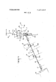
- FIG. 8 is a view taken generally alongthe lines 8-8 in FIG. 7.
- FIGS. 9 and are perspective views of one of the plurality of clamping assemblies carried by the conveyor shown in FIGS. 7A and 78, FIG. 9 being a view taken from the side shown and FIGS. 7A and 7B, and FIG. 10 being a view taken from the reverse side.
- the wire measuring devices 10, which are associated with the feed mechanisms 16, measure a plurality of wire leads, indicated at 24, to the same or. differing lengths.
- the plurality of wire leads which are handled by the wire measuring devices and feed mechanisms 10, 16 are still connected to their source of supply 26 and therefore they are referred to as supply wire leads.
- the source of supply 26 for the wire leads are conventional wire spools, although other sources of supply may be employed.
- the feedmechanisms 16 are mounted on a platform 28 for linear and rotational shifting movement and shifts the leading end of the wire leads 24 between a first position wherein terminals or the like are applied to the leading end of the measured wire leads, this position being shown in FIG.
- the cutting and stripping mechanism cuts through each of the wire leads at one point and cuts through the insulation to either side of the point which has been cut.
- the portion of the wire leads which are no longer connected to their source of supply will be referred to as the cut wire leads 29.
- the stripping action of the insulation from the end of the wire leads to either side of the point which has been cut is accomplished in part by an opposed linear shifting of the feed mechanisms 16 and transfer mechanism 100, the positions of the feed mechanisms 16 and transfer mechanism 100 after stripping being illustrated in FIG. 2.
- the transfer mechanism 100 which is disposed adjacent the cutting' and stripping mechanism 14receives the wire leads as they are fed past the cutting and stripping stations 14 and transfers the wire leads after they have been cut tothe conveyor means 200.
- the conveyor 200 transfers the plurality of cut wire leads 29 past the plurality of additional work performing structures 18, to the discharge station 22. As the plurality of cut wire leads 29 are transferred past the additional work performing stations 18, 20 additional work operations are performed upon the trailing ends of the cut wire leads 29, such as the assembling of terminals, bending of terminals, solder-dipping, applying insulating sleeves, etc.
- the wire measuring and feed mechanism 10, 16 may be of the type shown in US. Pat. No. 3,098,596 issued July 23', 1963 to Kulicke, Jr. et al.
- the above patent discloses a mechanism for measuring a predetermined length of wire lead and a pair of opposed feed wheels which feed the previously measured length of wire past a cutting apparatus.
- Two such measuring and feeding devices are schematically illustrated in FIGS. 1, 2, and 3, the feeding and measuring devices being capable of measuring the same or differing lengths of wire leads which may also be of differing diameters, and then feeding the wire leads past the cutting and stripping means 14.
- the feed mechanism 16 is mounted upon platform means 28, the platform means being laterally shiftable from a position wherein the feeding mechanism 16 is disposed immediately adjacent the cutting and stripping mechanism 14, as illustrated in FIG. 1, to a position wherein the cutting and feeding mechanism is disposed in a remote location, as indicated in FIG. 2, this lateral shifting movement effecting stripping of the insulation about the leading ends of the wire leads which have been cut by the cutting and stripping means 14.
- This lateral shifting movement is indicated by the arrow 30 in FIG. 2.
- the platform 28 can then be rotated in the manner indicated by the arrow 32 in FIG. 3 to present the bared leading ends of the supply wire leads 24 to a first terminal applicator 12 or the like.
- the feed mechanism is again positioned with one end of the feed mechanism immediately adjacent the cutting and stripping mechanism as indicated in FIG. 1.
- the plurality of supply wire leads are then fed past the cutting and stripping mechanism 14 and,'as there is one measuring and feed mechanism for each of the supply wire leads 24, differing lengths of wire leads may be fed past the cutting and stripping mechanism 14.
- the cutting and stripping mechanism 14 may be of the type shown in the previously mentioned U.S. Pat. No. 3,019,679 and includes means to shear the plurality of wire leads which have been fed past the cutting means, the shearing plane being indicated by the broken line 34 in FIGS. 1, 2, and 3.
- insulation parting blades are disposed to either side of the cutting means and may be in the planes indicated at 36 and 38, the insulation parting blades being preset to cut the insulation about the wire lead without severing the wire.
- the insulation parting blades are maintained in engagement with the wire leads after the insulation has been parted until the juxtapositioned ends of the wire leads 24, 29 are pulled away from each other to effect stripping of the insulation from the wire leads.
- the supply wire leads 24 are again provided with bared leading ends upon which terminals or the like may be affixed.
- the cut wire leads 29 are now provided with bared trailing end portions 40 (FIG. 5).
- the insulation parting blades in this apparatus are individually adjustable towards and away from the cutting means to provide for differing lengths of bared wire leads as desired.
- the transfer mechanism includes a holding assembly indicated generally at 102, the holding assembly being disposed adjacent one end of the transfer means.
- the transfer means further includes a trough portion 104, the trough portion having spaced apart sidewalls 106, 108 and a floor 109, all of which extend away from said holding assembly 102.
- the trough portion 104 and holding assembly are all mounted upon a slide 110 which is laterally shiftable from the cutting and stripping mechanism 14 as indicated by the arrow 112 (FIG. 2), and which may be returned to a position immediately adjacent the cutting and stripping mechanism as shown in FIG. 1.
- the holding assembly and trough portion can be shifted through linear movement of the slide from a first position, wherein the holding assembly is disposed adjacent the cutting and stripping mechanism and initially engages the wire leads fed past the cutting and stripping mechanism, this position being illustrated in FIG. 1, to an intermediate position wherein the holding means is spaced away from the cutting and stripping mechanism 14.
- the slide 110 is mounted on a pair of gibs 114, 116 (FIG. 7B) which are in turn mounted on a support 118.
- the support 118 is connected to pivot means 120 and rotation of the pivot means causes the holding assembly and trough portion to shift between the intermediate position shown in FIG. 2 to a second or transfer position which is shown in FIG. 3 wherein the holding assembly is disposed closely adjacent to the conveyor means 200, this shifting movement being indicated by the arrow 121 in FIG. 3. While no means have been shown for rotating the pivot means 120 a mechanism such as that shown in U.S. Pat. No. 3,019,679 may be employed.
- the holding assembly 102 of the transfer mechanism 100 includes fixed jaw means 122 and movable jaw means 124.
- the fixed jaw means are mounted in an overhanging portion 126 which is open to its left side, the right-hand side being in turn secured to a mounting block 127 which is interconnected with the slide 110.
- the fixed jaw means may, in fact, be formed from more than one structure and are secured to the overhanging means 126 by mounting pins 128.
- the movable jaw means 114 are mounted for vertical sliding movement between the mounting block 127 and a guide block 130. There is a movable jaw 124 for each of the pair of wire leads that pass the cutting and stripping means 14.
- Each of the movable jaws 124 has an upper portion which conforms generally to the fixed jaw means 122, the upper portion including a plurality of spaced apart sections 132 all of which have V-shaped notches 134.
- the mechanism for moving the movable jaws between their lower open position and closed upper position include levers 136, there being one lever for each of the jaws 124, all of the levers 136 being swingable about a pivot 138.
- each of the levers is provided with a bifurcated portion 140 which receives an actuating pin 142 within the slot 144 of the bifurcated portion.
- the pin extends between spaced apart lower ears 146 of each of the jaws, the bifurcated portion 140 also being disposed between the ears 146.
- Each of the levers has an end 148 remote from the bifurcated portion 140, the end being interconnected by pivot means 150 to a connecting link 152 which is in turn interconnected to the piston rod of an air cylinder in a manner not material to the present invention.
- the movable lower jaws 124 By actuating the piston rod in one direction the movable lower jaws 124 are caused to move away from the fixed upper jaw means 122, and when the piston rod is moved in the other direction the lower movable jaws 124 are moved toward the upper fixed jaw means 122.
- the force exerted by the air cylinders is relatively low and therefore when a wire lead is fully engaged by the V-shaped slots 134, the air cylinder or motor will effectively stall out, holding the wire leads, which may be of differing diameters, between the jaws 122, 124.
- the manner in which the connecting rods 152 are interconnected with the air motors is such that the holding assembly 102 can be shifted away from the cutting and stripping mechanism and towards its second position adjacent the conveyor means 200 while maintaining the jaws in engagement with eachother to hold cut wire leads.
- the left hand sidewall 106 of the trough portion 104 is provided with a cut-out 154.
- the purpose of the cut out is to permit a portion of the conveying means 200 to enter into the transfer means to properly receive the cut wire leads 29 so they may be effectively transferred to the conveyor means while maintaining proper spacings of the ends of the bared trailing ends 40 from the conveyor means so that subsequent work operations may be properly performed upon the trailing ends of the cut wire leads.
- the conveying means 200 is operable to convey and to index or sequentially position the bared trailing ends 40 of the cut wire leads 29 adjacent the plurality of additional work performing structures 18, 20.
- the conveyor means is formed preferably from an endless roller chain 202 (FIGS. 7A and 78), disposed over right and left hand sprockets 204, 206.
- the sprockets 204, 206 are disposed about shafts 208, 210, respectively.
- One of the shafts 208, 210 is a drive shaft, and drive means are provided to intermittently rotate the drive shaft to index or sequentially advance the endless roller chain.
- the drive means may be of the type shown in US. Pat.'No. 3,583,055 issued June 8, 1971 to l-Iammond.
- a plurality of clamping assemblies are mounted on the chain 202.
- Each of the plurality of clamp assemblies 212 is indexable from a first position adjacent the second position of the transfer means 100 (the first position being the position of the clamp assembly furthest to the right in FIG. 78) past the additional work operation performing means 18, to a second position adjacent the discharge station 22 (the second position being the position of the clamp assembly furthest to the left in FIG. 7A).
- Each of the clamping assemblies 212 includes a mounting plate 214 disposed to the front side of the roller chain, a mounting block 216 disposed to the rear side of the roller chain and fastener means 218, two of which pass through the roller chain and one of which passes through a spacer 22 0.
- each mounting block Supported on each mounting block are a plurality of independently operable clamping means indicated generally at 222 in FIGS. 9 and 10, there being a number of clamping means 222 on each clamping assembly 212 which is equal in number to the plurality of movable jaws 124 on the holding assembly 102 of the transfer mechanism 100.
- Each of the clamping means 222 includes fixed jaw means 224 and a movable jaw 226 which is shiftable towards and away from fixed jaw means 224.
- the fixed jaw means constitutes a single jaw as can be seen in FIGS. 9 and 10.
- Each of the movable jaws 226 is mounted on a shaft 228 which extends into a bore within the mounting block, the bore being closed at the end opposite from the movable jaw 226, and the shaft only extending part way into the bore.
- a compression spring 230 is mounted between the end of the shaft 228 remote from the movable jaw 226 and the closed ends of the bore and biases the movable jaw 226 toward the fixed jaw means 224.
- a screw 232 is threaded into the sides of each of the shafts 228, the. screw extending outwardly to one side of the mounting blocks 216 through elongated slots 234, the screws carrying cam followers 236.
- the cam followers 236 are disposed in alignment and are engagable by cam means indicated generally at 238 and 240 in FIGS. 7A and 78, respectively.
- the cam means 238 is disposed adjacent the discharge station and is cooperable with the cam follower means to provide for the discharge of processed cut wire leads 29.
- the cam means 240 is disposed adjacent the transfer means when it is in its second position and opens the clamping means 222 so that they may receive the cut wire leads from the transfer means 100.
- the right hand cam means 240 include a longitudinally shiftable or reciprocal bar 242 having a beveled edge 244 which engages the cam followers 236 to open the clamping means for the reception of the cut wire leads.
- the left hand end of the cam bar 242 is connected to a rock arm 246 by a pivoted link 248.
- the rock arm is in turn connected to a cam for rocking movement, the cam being rotated in timed relationship to the various other components of this apparatus.
- the cam means 238 is generally similar to the cam means 240, however, the cam bar 250 in addition to having a tapered end 252 also includes a stop 254 which is engagable with the processed cut wire leads as the cam bar 250 is extended to its left hand position indicated in FIG. 7A to facilitate the discharge of the processed wire leads from the clamping assemblies 212.
- the cam bar 250 is connected to a rock shaft (not shown) by a pivotal link 256. Means are provided to actuate the rock shaft in timed relationship with the various other components of this apparatus.
- the mounting plate 214 of each of the clamping assemblies is provided with a stabilizing surface means on the end remote from the clamping means 222.
- the stabilizing surfaces 260, 262 which are on the front and rear sides of the mounting plate 214 are disposable between one surface 264 of a disk 266 and an opposed surface 268 formed on one side of the hub portion 270 of the sprocket 206.
- a roller 272 is rotatably mounted upon the face 260 of the mounting plate 214 and bears against the top surface 273 of the disc 266. The front face 260 of the mounting plate 214 will be brought into the sliding contact with the surface 264 of the disc 266 when the roller 272 is in engagement with the top surface 273.
- stabilizing channels 274 are provided adjacent that run 276 of the conveyor which passes the various additional work performing structures 18, 20, there being one stabilizing channel 274 for each of the additional stations 18, 20 the stabilizing channels serving to stabilize the clamping assemblies as they are brought to a dwell position adjacent each of the stations.
- the inter-relationship of the stabilizing channel to the mounting plate 214 is substantially the same as the relationship between the mounting plate 214 and the disc 266.
- the roller 272 engages the upper surface 278 of the channel 274 forcing the front face 260 into sliding engagement with a co-operating surface of the channel 274 to very accurately position the clamping assembly 212 with respect to the associated work station 18, 20.
- FIG. 1 A complete cycle of the apparatus in which the principles of the present invention have been incorporated will be described below starting with the position shown in FIG. 1 in which the conveyor is shown with several pairs of wire leads engaged by various of the clamping assemblies which are mounted on the conveyor means, and also in which the supply wire leads are shown having terminals affixed to their leading ends and extending past the cutting and stripping means 14.
- the manner in which the terminals are applied to the leading ends of the supply wire leads, and the manner in which the several pairs of leads are loaded onto the plurality of clamping assemblies on the conveyor means will become apparent'from the following:
- the conveyor is shown after it has completed one cycle of movement wherein the clamping assemblies which are carrying cut wire leads have been moved from the position of the clamping assembly immediately to the right.
- the clamping assembly indicated at 212a has been moved from the position now occupied by the clamping assembly 2121).
- the pair of wire leads which are to be cut have been fed past the cutting and stripping means by the feeding means 16.
- the cam means 238 and 240 have been extended, the cam means 238 having effected the discharge, of processed cut wire leads to the discharge station 22, and the cam means 240 having opened the clamping means 222 for the reception of cut wire leads 29.
- the cutting and stripping means are moved together to shear the wire along the plane indicated by the line 34 and to shear the insulation about the wire generally along the lines indicated at-3 6 and 38.
- the stripping of the insulation from the leading and trailing end is now effectuated by movement of the platform 28' which carries the feeding means away from the cutting andstripping mechanism in .the direction indicated'by the arrow 30 (FIG. 2) and by simultaneous movement of the transfer mechanism away from the cutting and stripping means in the direction indicated by the arrow 112.
- the wire measuring means initiates measuring of new lengths of supply wire leads 24.
- the feeding means 16 are then swung in the direction indicated by the arrow 32 in FIG. 3 to present the bared leading ends to the terminal applicator 12.
- the transfer means 100 is swung in the direction indicated by the arrow 121 in FIG. 3 to dispose the cut wire leads 29 in a transfer position adjacent one of the clamping assemblies 212 on the conveyor means 200.
- FIGGS. 4 and 78 best illustrate the various relationships of the parts as the transfer means achieves its position adjacent the associated clamping assembly.
- Terminals or the like are applied to the bared leading ends of the supply wire leads 24 by the terminal applicator 12 after the platform 28 has completed its rotational movement.
- the cam means 238 and 240 are retracted towards each other which will cause the cut wire leads 29 to be engaged by the clamping means 222 disposed adjacent the transfer means.
- the clamping assembly 212 engaged by the left hand cam means 238 will merely close at this point as the processed cut wire leads have already been discharged.
- the movable jaws 124 Upon completion of the movement of the cam 240 to the left the movable jaws 124 will be opened by operation of the air cylinder (not shown) to effectuate transferof the cut wire leads 29 from the holding assembly on the transfer means to the clamping assemblies 212. While this transfer of cut wire leads is taking place terminals may be applied to the bared trailing ends of a cut wire-lead by the mechanisms 18, 20. Other similar operations may be performed by these mechanisms at this time.
- the conveyor is cycled causing the clamping assemblies which are carrying cut wire leads, including the clamping assembly which has just received wire leads to be moved one position to the left.
- the platform 28 is rotated in a direction opposite to the arrow 32 and is then moved to a position immediately adjacent the cutting and stripping means in a direction opposite to the arrow 30.
- the transfer mechanism 100 is swung in a direction reverse to the arrow 121 in FIG.
- the conveying of the leads need not be completed before the completion of the re-positioning of the transfer means 100 and platform to the position shown in FIG. 1 but should be completed prior to the initiation of the swinging motion of the transfer mechanism indicated by the arrow 121.
- a method of processing a plurality of wire leads comprising the following steps:
- steps B-E repeating steps B-E a number of times while simultaneously conveying the-additional plurality of wire leads past said plurality of additional work opera tion performing stations to said discharge station, and sequentially performing additional work operations on the bared trailing ends of said cut wire leads as they are conveyed past said additional work operation performing stations.
- cutting means operable to cut a plurality of supply wire leads, which extend away from a source of supply, to form an additional plurality of wire leads which still extend away from the source of supply, said plurality of cut and supply wire leads having opposed trailing and leading ends, respectively;
- stripping means operable to strip insulation from the opposed trailing and leading ends to form bared trailing and leading ends
- applying means operable to apply terminals or the like to one or more of the bared leading ends
- feeding means operable to independently measure and feed each of said plurality of supply wire leads past the cutting means after terminals or. the like have been applied to one or more of the bared leading ends;
- conveying means operable to convey and to sequentially position one or more bared trailing ends of said cut wire leads adjacent said plurality of spaced apart additional work operation performing means whereby additional work operations are performed on said one or more bared trailing ends.
- the apparatus for processing a plurality of wire leads set forth in claim 3 further characterized by the provision of transfer means between the conveying means and the cutting means.
- said transfer means includes a holding assembly which holds the plurality of wire leads after they have been fed past the cutting means and before they have been cut, means to shift the holding assembly linearly after the plurality of wire leads have been held, and the linear shifting of the holding assembly cooperating with the stripping means to strip insulation from the cut ends of the wire leads engaged by the transfer means, and means to rotate the holding assembly after it has shifted linearly to present the bared trailing ends of the cut wire leads to the conveyor means, and wherein said conveyor means moves the plurality of cut wire leads generally linearly and includes a plurality of clamping assemblies which are sequentially positioned adjacent the holding assemblies on the transfer means after the holding assembly has been rotated to effect transfer of the plurality of cut wire leads from the transfer means to the conveyor means.
- each of said plurality of clamp assemblies include a plurality of clamping means.
- a lead processing apparatus including cutting means operable to cut a plurality of supply wire leads, which extend away from a source of supply, to form an additional plurality of cut wire leads which are initially in register with the plurality of wire leads which still extend away from the source of supply, all of said plurality of cut and supply wire leads having opposed trailing and leading ends, respectively; stripping means disposed to either side of the cutting means operable to strip insulation from the opposed trailing and leading ends to form bared trailing and leading ends; applying means disposed to one side of said cutting means and operable to apply terminals or the like to one or more of the bared leading ends; feeding means disposed to the same side of the cutting means as the applying means, said feeding means being operable to feed each of said plurality of supply wires past the cutting means after terminals or the like have been applied to one or more of the bared leading ends; one or more additional work operation performing means operable to perform additional work operations on one or more of the bared trailing ends of the cut wire leads when said ends are positioned adjacent the work
- a discharge station which receives a plurality of processed cut wire leads the combination therewith of transfer means disposed to one side of the cutting means opposite that side on which the applying means and feeding means is disposed, said transfer means receiving the plurality of wire leads fed past the cutting means by said feeding means, and being operable to transfer the bared trailing ends of said plurality of cut wire leads away from said cutting and stripping means;
- conveyor means which receive said plurality of cut wire leads from the transfer means afterthe trailing ends have been transferred away from said cutting means, said conveyor means indexing the bared trailing ends past said one or more additional work operation performing means for processing of the bared trailing ends when they are adjacent the work operation performing means, said conveyor means discharging the plurality of processed cut wire leads to said discharge station.
- said conveyor means includes an endless conveyor having one run which passes said one or more additional work operation performing means, and a plurality of clamp assemblies mounted on said endless conveyor, each of said plurality of clamp assemblies including a plurality of clamping means, each of the clamping means receiving one of the plurality of cut wire leads when the clamp assembly is disposed adjacent the transfer means, each of said clamping means maintaining clamping engagement of one of the plurality of cut wire leads as they are indexed along said one run.
- each of said clamping means includes fixed jaw means and a movable jaw shiftable between a closed position adjacent said fixed jaw means and an open position remote from said fixed jaw means, means operable to spring bias the movable jaw towards its closed position, and means engagable to move said movable jaw to an open position when the clamping means is disposed adjacent the transfer means so that each of the clamping means may receive one of the plurality of cut wire leads from the transfer means.
- said means engagable to move said movable jaw to an open position includes a cam follower means, said conveying means further including cam means engagable with said cam follower means for each of said clamping means when a clamp assembly is disposed adjacent the transfer means.
- said conveyor means includes an endless roller chain disposed about spaced apartsprockets, a plurality of spaced apart clamp assemblies mounted upon said chain, and wherein stabilizing means are provided on each of said clamp assemblies to stabilize said clamp assemblies in various positions as they are indexed from one end of the conveyor to the other end.
- the conveyor means includes stabilizing discs mounted concentrically with each of said sprockets, said stabilizing discs cooperating with the stabilizing means on each of the clamp assemblies to stabilize said clamp assemblies as they pass around said sprocket means, and wherein said conveying means also includes stabilizing channels disposed adjacent each of the additional work operation performing means, said stabilizing channels cooperating with the stabilizing means on the clamp assemblies to stabilize the clamp assemblies adjacent each of the one or more additional work operation performing means.
- the transfer means includes a holding assembly operable to hold the plurality of cut wire leads after they have been fed past the cutting means, means to shift the holding assembly linearly away from the cutting means, the linear shifting of the holding assembly cooperating with the stripping means to strip insulation from the cut ends of the wire leads engaged by the holding assembly on the transfer means, and means to rotate the holding assembly after it has shifted linearly to dispose the bared trailing ends of the cut wire leads adjacent the conveyor means.
- the holding assembly on the transfer means includes fixed jaw means and a plurality of movable jaw means equal in number to the plurality of cut wire leads.
- said transfer means include a trough portion which extends away from the holding means, the wire leads being fed into said trough means past said holding assembly, one of the sidewalls of said trough being provided with a cut-out, said conveyor means including an endless conveyor having aplurality of clamp assemblies mounted thereon, the means which rotates the holding assembly positioning the holding assembly adjacent the conveyor means with one of said clamp assemblies mounted on the conveyor means extending into the trough portion of said transfer means through said cut-out.
- clamp assemblies on the conveyor include a plurality of clamping means
- the holding assembly on said transfer means includes a plurality of holding means equal in number to the clamping means on the clamping assemblies of the conveyor means, the plurality of holding means on the transfer means being disposed in alignment with the plurality of clamping means on the clamping assemblies of the conveyor means so that the cut wire leads engaged by each of the holding means on the transfer means is transferred to a respective clamping means on the clamping assembly disposed within said cut-out.
- transfer means having a holding assembly disposed adjacent one end of said transfer means and a trough portion having spaced apart sidewalls extending away from said holding assembly and means to shift the holding assembly and trough portion between a first position wherein the holding assembly initially engage the plurality of wire leads to a second position wherein the plurality of wire leads are transferred; and one of the sidewalls of the trough means having an opening therein adjacent said holding assembly, and said holding assembly including fixed jaw means and a plurality of independently operable movable jaws normally biased towards the fixed jaw means, each of the movable jaws normally engaging one of said plurality of wire leads of differing diameters;
- conveyor means including a plurality of clamp assemblies indexable from a first position adjacent the second position of the transfer means past the plurality of additional work stations to a second position adjacent the discharge station, each of said clamp assemblies including a plurality of independently operable movable jaws on holding assembly of said transfer means, the movable jaws on the transfer means and clamping means on the clamp ing assemblies being disposed in register with each other when said transfer means is in its first position to effect transfer of the wire leads from the transfer means to the conveying means.
- An apparatus to measure, cut and strip a pair of wire leads of differing diameters and lengths, and to apply terminals to the leading and trailing ends of each of said cut pair of wire leads comprising;
- cutting means operable to cut a pair of supply wire leads of differing diameters which extend away from a source of supply to form an additional pair of cut wire leads which still extend away from the source of supply, said pairs of cut and supply wire leads having opposed trailing and leading ends respectively;
- stripping means operable to strip insulation from opposed trailing and leading ends to form bared trailing and leading ends
- first terminal applying means operable to apply a pair of terminals, one to each of the bared leading ends
- feeding means operable to independently measure differing lengths of each of said pairs of wire leads which extend away from the source of supply and to feed the differing measured lengths of said wire leads past the cutting means after the pair of terminals has been applied to the bared leading ends;
- transfer means including a pair of holding means and means to shift said pair of holding means as they hold a cut pair of wire leads between a first position wherein the pair of holding means initially engages the cut pair of cut wire leads to a second position wherein the cut pair of wire leads are transferred, one of said pair of holding means engaging one of said cut pair of wire leads, and the other of said pair of holding means engaging the other of said cut pair of wire leads;
- endless conveyor means including a plurality of clamp assemblies mounted thereon, each clamp assembly being movable from a first position adjacent the second position of the pair of holding means to a second position where cut pairs of wire leads are discharged, each of said clamp assemblies including a pair of clamping means, the pair of holding means on the transfer means and the pair of clamping means on one of the clamping assemblies being disposed in register with each other when said transfer means is in its second position and said one clamping assembly is in its first position to effect transfer of the pair of wire leads from the transfer means to the clamping assembly, one clamping means engaging one of said pair of cut wire leads, and the other clamping means engaging the other of said cut pair of wire leads, and
- second and third terminal applying means disposed adjacent said endless conveyor means and operable to apply terminals to said bared trailing ends, said clamp assemblies moving past said second and third terminal applying means as they move from their first position to their second position, said endless conveyor means presenting the bared trailing end of one of the pair of wire leads to the second terminal applying means for application of a terminal to said bared trailing end, and the endless conveyor means also presenting the bared trailing end of the other of said pair of wire leads to the third terminal applying means for application of a terminal to the bared trailing end of said other of said pair of wire leads.
Landscapes
- Engineering & Computer Science (AREA)
- Manufacturing & Machinery (AREA)
- Manufacturing Of Electrical Connectors (AREA)
- Wire Processing (AREA)
- Removal Of Insulation Or Armoring From Wires Or Cables (AREA)
Abstract
A fully automatic apparatus which measures, cuts and strips a plurality of wire leads, which may be of differing diameters and lengths, which applies terminals or the like to the leading ends of the wire leads, and which transfers the plurality of cut wire leads to a conveyor which subsequently indexes the trailing ends of the cut wire leads past a plurality of terminal applicators or other work performing structures to a discharge station. The various components of the apparatus include a wire measuring device, a first terminal applicator or the like, a cutting and stripping mechanism, a feed mechanism, a transfer mechanism, a conveyor, a plurality of additional work performing structures, and a discharge station. The wire measuring device, which is associated with the feed mechanism, measures a plurality of wire leads to differing lengths. The feed mechanism shifts the leading end of the wire leads between a first position, wherein terminals or the like are applied to the leading ends of the measured wire leads, and a second position wherein the feed mechanism feeds the pre-measured lengths of wire leads past the cutting and stripping mechanism. The transfer mechanism which is disposed adjacent the cutting and stripping mechanisms, receives the cut wire leads and transfers them to the conveyor. The conveyor, which has a plurality of clamp assemblies mounted on an endless chain, conveys the cut wire leads past the additional work performing structures to the discharge station. Additional work operations are performed upon the trailing ends of the cut wire leads, such as the assembling of terminals, etc., as the cut wire leads are conveyed.
Description
United States Patent [191 Chick et a1.
[ Mar. 25, 1975 METHOD AND APPARATUS FOR PROCESSING A PLURALITY OF WIRE LEADS [75] Inventors: Joseph James Chick,
Mechanicsburg; Thomas Joseph Bozek, Jr., Harrisburg; James Woodrow Hammond, Camp Hill, all of Pa.
[73] Assignee: AMP Incorporated, Harrisburg, Pa.
[22] Filed: Feb. 27, 1974 [21] Appl. No.: 446,553
[52] US. Cl 29/630 A, 29/33 M, 29/203 DT, 81/951 [51] Int. Cl. H0lr 9/00, H0lr 43/04 [58] Field of Search..... 29/200 DT, 203 D8, 630 A, 29/33 M; 81/951 [56] References Cited UNITED STATES PATENTS 3,019,679 2/1962 Schwalm 81/951 3,184,950 5/1965 Sitz 29/203 DS 3,267,556 8/1966 Scharf 29/630 A 3,583,055 6/1971 Hammond 29/203 DT Primary Examiner-Thomas H. Eager Attorney, Agent, or FirmWilliam J. Keating; Jay L. Seitchik; Frederick W. Raring [57] ABSTRACT A fully automatic apparatus which measures, cuts and strips a plurality of wire leads, which may be of differing diameters and lengths, which applies terminals or the like to the leading ends of the wire leads, and which transfers the plurality of cut wire leads to a conveyor which subsequently indexes the trailing ends of the cut wire leads past a plurality of terminal applicators or other work performing structures to a discharge station. The various components of the apparatus include a wire measuring device, a first terminal applicator or the like, a cutting and stripping mechanism, a feed mechanism, a transfer mechanism, a conveyor, a plurality of additional work performing structures, and a discharge station. The wire measuring device, which is associated with the feed mechanism, measures a plurality of wire leads to differing lengths. The feed mechanism shifts the leading end of the wire leads between a first position, wherein terminals or the like are applied to the leading ends of the measured wire leads, and a second position wherein the feed mechanism feeds the pre-measured lengths of wire leads past the cutting and stripping mechanism. The transfer mechanism which is disposed adjacent the cutting and stripping mechanisms, receives the cut wire leads and transfers them to the conveyor. The conveyor, which has a plurality of clamp assemblies mounted on an endless chain, conveys the cut wire leads past the additional work performing structures to the discharge station. Additional work operations are performed upon the trailing ends of the cut wire leads, such as the assembling of terminals, etc., as the cut wire leads are conveyed.
22 Claims, 11 Drawing Figures PATENTED HARZ 5 I875 mmsmg PATENTEB MAR 2 51975 SHEET 8 [IF 8 FIELD OF THE INVENTION The present invention relates generally to a method and apparatus for processing a plurality of wire leads, and more particularly, to a method and apparatus capable of applying terminals or performing other work operations on both ends of groups of pluralities of wire leads which may be of differing lengths and diameters.
BACKGROUND OF THE INVENTION Various machines are well-known in the prior art for processing wire leads wherein terminals are applied to one orboth ends 'of one or two wire leads. One such apparatus is shown in the Schwalm et al US. Pat. No. 3,019,678 issued Feb. 6, 1962. In this machine, which is known in the trade as an Ampomator automatic lead making machine, a wire lead is fed into a first transfer mechanism which presents the leading end of the wire lead (which is connected to a source of the supply) to a first terminal applicator, applies a terminal to the leading end of the wire lead, and then positions the wire lead in a second position wherein it is fed past cutting and stripping means, the wire lead fed past the cutting and stripping means being received by a second transfer means, the machine further cutting and stripping the wire lead between the end which has a terminal initially affixed thereto and its source of supply, the trailing end of the cut wire lead then being transferred to a second terminal applicator. After a terminal is applied to the trailing end the wire lead is then discharged from the machine. The machine shown in the patent is capable of processing only a single wire. A commercial variation of the machine shown in the Patent, which is known as the Model IV-C, is capable of processing two wire leads, however, in this model both wire leads should be of substantially the same diameter. Furthermore, as the terminal applicators which apply terminals to the trailing ends of the cut wire leads are disposed in close side-by-side relationship to each other, it is not practical to perform substantially different work operations upon the end of the cut wire leads, such as bending terminals, solder dipping, applying insulating sleeves, etc.
The Hammond US. Pat. No. 3,583,055 issued June 8, I971 discloses an apparatus which measures and cuts a pair of wire leads and presents the ends of the paired wire leads sequentially to spaced apart work stations which are capable of performing varying work operations upon the trailing and leading ends of the wire leads. While the machine shown in this Patent has gained widespread commercial acceptance, it has the disadvantage in that each pair of wires is of substantially the same length and of substantially the same diameter.
The Scharf US. Pat. No. 3,267,556 issued Aug. 23, I966 discloses an apparatus which applies a terminal to the leading end of a wire lead which extends away from a source of supply,,feeds the wire past a cutting and stripping mechanism after the terminal or the like has been applied to the leading end, and provides a conveyor mounted upon endless roller chains which conveys the trailing end of the wire lead after it has been out past another terminal applicator. This prior art machine has the disadvantage in that it is incapable of simultaneously processing a plurality of wire leads which may be of differing diameters and lengths.
OBJECTS OF THE INVENTION It is a general object of the present invention to provide a fully automatic machine which is capable of measuring, cutting and stripping two or more wire leads (which may be of differing diameters and lengths), applying terminals or the like to a leading end of one or more of the wire leads, and being capable of performing diverse operations (including terminal applying) upon the trailing ends of the wire leads.
More specifically, it is an object ofthe present invention to provide a novel fully automatic apparatus capable of independently feeding each of a plurality of supply wire leads from a source of supply past a cutting and stripping station in varying increments wherein one or more of the leading ends of the plurality of wire leads have terminals or the like thereon, cutting all of the supply wire leads to form an additional plurality of cut wire leads, stripping insulation from all of the plurality of supply and cut wire leads, applying a terminal or the like to one or more of the stripped leading ends and transferring the plurality of cut wire leads away from the cutting and stripping station to a location adjacent a conveyor capable of carrying several pluralities of cut wire leads, and (while repeating the foregoing steps a number of times) conveying the plurality of cut wire leads away from said location to a discharge station while performing additional sequential operations upon the trailing ends of the cut wire leads.
It is another object of the present invention to provide a novel apparatus for transferring and conveying a plurality of wire leads of differing diameters from a first work area wherein terminals'are applied to the leading ends of the wire leads to a second work area where diverse sequential operations may be performed upon the trailing ends of the wire leads.
These and other objects of the present invention will be apparent to those having ordinary skill in the art after a consideration of the following detailed description with reference to the accompanying drawings in which a preferred form of the present invention is illustrated.
BRIEF DESCRIPTION OF THE DRAWINGS FIGS. 1, 2, and 3 are schematic plan views of the apparatus in which the principles of the present invention are embodied, these views illustrating various relationships of different portions of the apparatus to each other in various stages of the operational sequence of the apparatus.
FIG. 4 is a section taken along the line 44 in FIG. 3 showing a transfer mechanism which is employed in the apparatus disposed adjacent to a conveyor means which is also employed in the apparatus.
FIG. 5 is a side view of the transfer mechanism taken from the opposite side illustrated in FIG. 4.
FIG. 6is an end view of the transfer mechanism taken along the lines 6-6 of FIG. 5.
FIGS. 7A and 7B are views illustrating the left-hand portion and right-hand portion, respectively, of the conveyor, FIG. 7B additionally illustrating the transfer mechanism when it is disposed in the position shown in FIG. 3.
FIG. 8 is a view taken generally alongthe lines 8-8 in FIG. 7.
FIGS. 9 and are perspective views of one of the plurality of clamping assemblies carried by the conveyor shown in FIGS. 7A and 78, FIG. 9 being a view taken from the side shown and FIGS. 7A and 7B, and FIG. 10 being a view taken from the reverse side.
DESCRIPTION OF THE PREFERRED EMBODIMENT In the following description right hand and left hand reference will refer to the positions shown in FIGS. 1 through 3. Similarly, front and rear references will refer to the positions shown in FIGS. 1 through 3, the rear position being considered that at the top of the Figures and the front position being that at the bottom of the Figures.
IN GENERAL The various components of the apparatus shown in the drawings in which the principles of the present invention are embodied include two wire measuring devices, indicated generally at 10, a first terminal applicator or the like, indicated generally at 12, a cutting and stripping mechanism, indicated generally at 14, a pair of feed mechanisms, indicated generally at 16, a plurality of additional work performing structures, indicated generally at 18 and 20, a discharge station indicated generally at 22, a transfer mechanism indicated generally at 100, and a conveying means indicated generally at 200.
The wire measuring devices 10, which are associated with the feed mechanisms 16, measure a plurality of wire leads, indicated at 24, to the same or. differing lengths. The plurality of wire leads which are handled by the wire measuring devices and feed mechanisms 10, 16 are still connected to their source of supply 26 and therefore they are referred to as supply wire leads. The source of supply 26 for the wire leads are conventional wire spools, although other sources of supply may be employed. The feedmechanisms 16 are mounted on a platform 28 for linear and rotational shifting movement and shifts the leading end of the wire leads 24 between a first position wherein terminals or the like are applied to the leading end of the measured wire leads, this position being shown in FIG. 3, and a second position wherein the feed mechanisms 16 feeds the measured lengths of supply wire leads 24 past the cutting and stripping mechanism 14, this second position being shown in FIG. 1. The cutting and stripping mechanism cuts through each of the wire leads at one point and cuts through the insulation to either side of the point which has been cut. The portion of the wire leads which are no longer connected to their source of supply will be referred to as the cut wire leads 29. The stripping action of the insulation from the end of the wire leads to either side of the point which has been cut is accomplished in part by an opposed linear shifting of the feed mechanisms 16 and transfer mechanism 100, the positions of the feed mechanisms 16 and transfer mechanism 100 after stripping being illustrated in FIG. 2. The transfer mechanism 100, which is disposed adjacent the cutting' and stripping mechanism 14receives the wire leads as they are fed past the cutting and stripping stations 14 and transfers the wire leads after they have been cut tothe conveyor means 200. The conveyor 200 transfers the plurality of cut wire leads 29 past the plurality of additional work performing structures 18, to the discharge station 22. As the plurality of cut wire leads 29 are transferred past the additional work performing stations 18, 20 additional work operations are performed upon the trailing ends of the cut wire leads 29, such as the assembling of terminals, bending of terminals, solder-dipping, applying insulating sleeves, etc.
Various of the components enumerated above are generally conventional to the art and therefore have not been fully illustrated in the accompanying drawings. However, in the accompanying description reference will be made to various patents which illustrate some of the components set forth above.
While the apparatus shown in the drawings is designed to handle two wire leads of differing diameters, it should be obvious to those having ordinary skill in the art that more than two wire leads may be handled by an apparatus embodying the present invention and that the wire leads need not be of differing diameters.
As will become apparent from the following description, it is necessary that the various components of the apparatus of this invention operate in timed sequence relativeto each other. The drives for the various components have not been illustrated nor have their interrelationships with respect to each other been shown, however, suitable means may be employed for driving the various components.
MEASURING AND FEEDING MECHANISMS, FIRST TERMINAL APPLICATOR, AND CUTTING AND STRIPPING MECHANISM The wire measuring and feed mechanism 10, 16 may be of the type shown in US. Pat. No. 3,098,596 issued July 23', 1963 to Kulicke, Jr. et al. The above patent discloses a mechanism for measuring a predetermined length of wire lead and a pair of opposed feed wheels which feed the previously measured length of wire past a cutting apparatus. Two such measuring and feeding devices are schematically illustrated in FIGS. 1, 2, and 3, the feeding and measuring devices being capable of measuring the same or differing lengths of wire leads which may also be of differing diameters, and then feeding the wire leads past the cutting and stripping means 14.
The feed mechanism 16 is mounted upon platform means 28, the platform means being laterally shiftable from a position wherein the feeding mechanism 16 is disposed immediately adjacent the cutting and stripping mechanism 14, as illustrated in FIG. 1, to a position wherein the cutting and feeding mechanism is disposed in a remote location, as indicated in FIG. 2, this lateral shifting movement effecting stripping of the insulation about the leading ends of the wire leads which have been cut by the cutting and stripping means 14. This lateral shifting movement is indicated by the arrow 30 in FIG. 2. Once the feeding mechanisms 16 have been shifted away from the cutting and stripping mechanism 14, the platform 28 can then be rotated in the manner indicated by the arrow 32 in FIG. 3 to present the bared leading ends of the supply wire leads 24 to a first terminal applicator 12 or the like. A mechanism which may provide for such lateral shifting and rotary movement of the feed means is illustrated in US. Pat. No. 3,019,679 issued Feb. 6, 1962 to Schwalm et al. Other means are well-known in the art. The terminal applicator may be of the type shown in US. Pat. No. 3,184,950, the applicator being mounted in a press of the type shown in US. Pat. No. 3,343,398. Other applicators and presses may be employed, however, the applicators should be of such a type that, when desired, they may simultaneously perform a terminal application upon two or more closely positioned wire leads.
- After terminals or the like have been applied to the leading ends of the supply wire leads 24, the feed mechanism is again positioned with one end of the feed mechanism immediately adjacent the cutting and stripping mechanism as indicated in FIG. 1. The plurality of supply wire leads are then fed past the cutting and stripping mechanism 14 and,'as there is one measuring and feed mechanism for each of the supply wire leads 24, differing lengths of wire leads may be fed past the cutting and stripping mechanism 14. The cutting and stripping mechanism 14 may be of the type shown in the previously mentioned U.S. Pat. No. 3,019,679 and includes means to shear the plurality of wire leads which have been fed past the cutting means, the shearing plane being indicated by the broken line 34 in FIGS. 1, 2, and 3. In addition, insulation parting blades are disposed to either side of the cutting means and may be in the planes indicated at 36 and 38, the insulation parting blades being preset to cut the insulation about the wire lead without severing the wire. As is conventional, the insulation parting blades are maintained in engagement with the wire leads after the insulation has been parted until the juxtapositioned ends of the wire leads 24, 29 are pulled away from each other to effect stripping of the insulation from the wire leads. When this is accomplished the supply wire leads 24 are again provided with bared leading ends upon which terminals or the like may be affixed. The cut wire leads 29 are now provided with bared trailing end portions 40 (FIG. 5). The insulation parting blades in this apparatus are individually adjustable towards and away from the cutting means to provide for differing lengths of bared wire leads as desired.
TRANSFER MECHANISM According to the principles of the present invention a novel transfer mechanism 100 'is provided. The transfer mechanism includes a holding assembly indicated generally at 102, the holding assembly being disposed adjacent one end of the transfer means. The transfer means further includes a trough portion 104, the trough portion having spaced apart sidewalls 106, 108 and a floor 109, all of which extend away from said holding assembly 102. The trough portion 104 and holding assembly are all mounted upon a slide 110 which is laterally shiftable from the cutting and stripping mechanism 14 as indicated by the arrow 112 (FIG. 2), and which may be returned to a position immediately adjacent the cutting and stripping mechanism as shown in FIG. 1. While no mechanism has been illustrated for reciprocating the slide 110, a mechanism of the type shown in U.S. Pat. No. 3,019,679 may be employed. Thus, the holding assembly and trough portion can be shifted through linear movement of the slide from a first position, wherein the holding assembly is disposed adjacent the cutting and stripping mechanism and initially engages the wire leads fed past the cutting and stripping mechanism, this position being illustrated in FIG. 1, to an intermediate position wherein the holding means is spaced away from the cutting and stripping mechanism 14. The slide 110 is mounted on a pair of gibs 114, 116 (FIG. 7B) which are in turn mounted on a support 118. The support 118 is connected to pivot means 120 and rotation of the pivot means causes the holding assembly and trough portion to shift between the intermediate position shown in FIG. 2 to a second or transfer position which is shown in FIG. 3 wherein the holding assembly is disposed closely adjacent to the conveyor means 200, this shifting movement being indicated by the arrow 121 in FIG. 3. While no means have been shown for rotating the pivot means 120 a mechanism such as that shown in U.S. Pat. No. 3,019,679 may be employed.
The holding assembly 102 of the transfer mechanism 100 includes fixed jaw means 122 and movable jaw means 124. The fixed jaw means are mounted in an overhanging portion 126 which is open to its left side, the right-hand side being in turn secured to a mounting block 127 which is interconnected with the slide 110. The fixed jaw means may, in fact, be formed from more than one structure and are secured to the overhanging means 126 by mounting pins 128. The movable jaw means 114 are mounted for vertical sliding movement between the mounting block 127 and a guide block 130. There is a movable jaw 124 for each of the pair of wire leads that pass the cutting and stripping means 14. Each of the movable jaws 124 has an upper portion which conforms generally to the fixed jaw means 122, the upper portion including a plurality of spaced apart sections 132 all of which have V-shaped notches 134. When the lower movable jaws 124 are positioned to receive a wire lead they will be spaced away from the upper fixed jaw'means 122 in the manner shown in FIG. 5 in full lines. However, to hold a wire lead they are moved to their closed position which is indicated in broken lines in FIG. 5. The mechanism for moving the movable jaws between their lower open position and closed upper position include levers 136, there being one lever for each of the jaws 124, all of the levers 136 being swingable about a pivot 138. The forward end of each of the levers is provided with a bifurcated portion 140 which receives an actuating pin 142 within the slot 144 of the bifurcated portion. The pin extends between spaced apart lower ears 146 of each of the jaws, the bifurcated portion 140 also being disposed between the ears 146. Each of the levers has an end 148 remote from the bifurcated portion 140, the end being interconnected by pivot means 150 to a connecting link 152 which is in turn interconnected to the piston rod of an air cylinder in a manner not material to the present invention. By actuating the piston rod in one direction the movable lower jaws 124 are caused to move away from the fixed upper jaw means 122, and when the piston rod is moved in the other direction the lower movable jaws 124 are moved toward the upper fixed jaw means 122. The force exerted by the air cylinders is relatively low and therefore when a wire lead is fully engaged by the V-shaped slots 134, the air cylinder or motor will effectively stall out, holding the wire leads, which may be of differing diameters, between the jaws 122, 124. The manner in which the connecting rods 152 are interconnected with the air motors is such that the holding assembly 102 can be shifted away from the cutting and stripping mechanism and towards its second position adjacent the conveyor means 200 while maintaining the jaws in engagement with eachother to hold cut wire leads.
The left hand sidewall 106 of the trough portion 104 is provided with a cut-out 154. The purpose of the cut out is to permit a portion of the conveying means 200 to enter into the transfer means to properly receive the cut wire leads 29 so they may be effectively transferred to the conveyor means while maintaining proper spacings of the ends of the bared trailing ends 40 from the conveyor means so that subsequent work operations may be properly performed upon the trailing ends of the cut wire leads.
CONVEYING MEANS The conveying means 200 is operable to convey and to index or sequentially position the bared trailing ends 40 of the cut wire leads 29 adjacent the plurality of additional work performing structures 18, 20. The conveyor means is formed preferably from an endless roller chain 202 (FIGS. 7A and 78), disposed over right and left hand sprockets 204, 206. The sprockets 204, 206 are disposed about shafts 208, 210, respectively. One of the shafts 208, 210 is a drive shaft, and drive means are provided to intermittently rotate the drive shaft to index or sequentially advance the endless roller chain. The drive means may be of the type shown in US. Pat.'No. 3,583,055 issued June 8, 1971 to l-Iammond. A plurality of clamping assemblies, indicated generally at 212, are mounted on the chain 202. Each of the plurality of clamp assemblies 212 is indexable from a first position adjacent the second position of the transfer means 100 (the first position being the position of the clamp assembly furthest to the right in FIG. 78) past the additional work operation performing means 18, to a second position adjacent the discharge station 22 (the second position being the position of the clamp assembly furthest to the left in FIG. 7A). Each of the clamping assemblies 212 includes a mounting plate 214 disposed to the front side of the roller chain, a mounting block 216 disposed to the rear side of the roller chain and fastener means 218, two of which pass through the roller chain and one of which passes through a spacer 22 0. Supported on each mounting block are a plurality of independently operable clamping means indicated generally at 222 in FIGS. 9 and 10, there being a number of clamping means 222 on each clamping assembly 212 which is equal in number to the plurality of movable jaws 124 on the holding assembly 102 of the transfer mechanism 100. Each of the clamping means 222 includes fixed jaw means 224 and a movable jaw 226 which is shiftable towards and away from fixed jaw means 224. The fixed jaw means constitutes a single jaw as can be seen in FIGS. 9 and 10. Each of the movable jaws 226 is mounted on a shaft 228 which extends into a bore within the mounting block, the bore being closed at the end opposite from the movable jaw 226, and the shaft only extending part way into the bore. A compression spring 230 is mounted between the end of the shaft 228 remote from the movable jaw 226 and the closed ends of the bore and biases the movable jaw 226 toward the fixed jaw means 224. A screw 232 is threaded into the sides of each of the shafts 228, the. screw extending outwardly to one side of the mounting blocks 216 through elongated slots 234, the screws carrying cam followers 236. The cam followers 236 are disposed in alignment and are engagable by cam means indicated generally at 238 and 240 in FIGS. 7A and 78, respectively. The cam means 238 is disposed adjacent the discharge station and is cooperable with the cam follower means to provide for the discharge of processed cut wire leads 29.
The cam means 240 is disposed adjacent the transfer means when it is in its second position and opens the clamping means 222 so that they may receive the cut wire leads from the transfer means 100. The right hand cam means 240 include a longitudinally shiftable or reciprocal bar 242 having a beveled edge 244 which engages the cam followers 236 to open the clamping means for the reception of the cut wire leads. The left hand end of the cam bar 242 is connected to a rock arm 246 by a pivoted link 248. The rock arm is in turn connected to a cam for rocking movement, the cam being rotated in timed relationship to the various other components of this apparatus. The cam means 238 is generally similar to the cam means 240, however, the cam bar 250 in addition to having a tapered end 252 also includes a stop 254 which is engagable with the processed cut wire leads as the cam bar 250 is extended to its left hand position indicated in FIG. 7A to facilitate the discharge of the processed wire leads from the clamping assemblies 212. The cam bar 250 is connected to a rock shaft (not shown) by a pivotal link 256. Means are provided to actuate the rock shaft in timed relationship with the various other components of this apparatus.
The mounting plate 214 of each of the clamping assemblies is provided with a stabilizing surface means on the end remote from the clamping means 222. The stabilizing surfaces 260, 262 which are on the front and rear sides of the mounting plate 214 are disposable between one surface 264 of a disk 266 and an opposed surface 268 formed on one side of the hub portion 270 of the sprocket 206. A roller 272 is rotatably mounted upon the face 260 of the mounting plate 214 and bears against the top surface 273 of the disc 266. The front face 260 of the mounting plate 214 will be brought into the sliding contact with the surface 264 of the disc 266 when the roller 272 is in engagement with the top surface 273. This will very accurately position the clamping assembly 212 with respect to the holding assembly 102 on the transfer mechanism when the clamping assembly 212 is disposed adjacent the transfer mechanism as illustrated in FIG. 4. Thus, the end of the bared trailing end 40 of each of the cut wire leads is disposed at a substantially fixed distance away from the clamping means 222 which engages the cut wire lead. This precise positioning of cut wire lead 29 within the clamping means 222 of the conveyor means 200 is essential to accurately position the trailing end leads for subsequent operations at the work stations 18, 20.
In addition, stabilizing channels 274 are provided adjacent that run 276 of the conveyor which passes the various additional work performing structures 18, 20, there being one stabilizing channel 274 for each of the additional stations 18, 20 the stabilizing channels serving to stabilize the clamping assemblies as they are brought to a dwell position adjacent each of the stations. The inter-relationship of the stabilizing channel to the mounting plate 214 is substantially the same as the relationship between the mounting plate 214 and the disc 266. Thus, the roller 272 engages the upper surface 278 of the channel 274 forcing the front face 260 into sliding engagement with a co-operating surface of the channel 274 to very accurately position the clamping assembly 212 with respect to the associated work station 18, 20.
OPERATION A complete cycle of the apparatus in which the principles of the present invention have been incorporated will be described below starting with the position shown in FIG. 1 in which the conveyor is shown with several pairs of wire leads engaged by various of the clamping assemblies which are mounted on the conveyor means, and also in which the supply wire leads are shown having terminals affixed to their leading ends and extending past the cutting and stripping means 14. The manner in which the terminals are applied to the leading ends of the supply wire leads, and the manner in which the several pairs of leads are loaded onto the plurality of clamping assemblies on the conveyor means will become apparent'from the following:
a In the position shown in FIG. 1, the conveyor is shown after it has completed one cycle of movement wherein the clamping assemblies which are carrying cut wire leads have been moved from the position of the clamping assembly immediately to the right. For example, the clamping assembly indicated at 212a has been moved from the position now occupied by the clamping assembly 2121). The pair of wire leads which are to be cut have been fed past the cutting and stripping means by the feeding means 16. The cam means 238 and 240 have been extended, the cam means 238 having effected the discharge, of processed cut wire leads to the discharge station 22, and the cam means 240 having opened the clamping means 222 for the reception of cut wire leads 29.
At this point the cutting and stripping means are moved together to shear the wire along the plane indicated by the line 34 and to shear the insulation about the wire generally along the lines indicated at-3 6 and 38. The stripping of the insulation from the leading and trailing end is now effectuated by movement of the platform 28' which carries the feeding means away from the cutting andstripping mechanism in .the direction indicated'by the arrow 30 (FIG. 2) and by simultaneous movement of the transfer mechanism away from the cutting and stripping means in the direction indicated by the arrow 112. As this movement is taking place the wire measuring means initiates measuring of new lengths of supply wire leads 24.
Afterthe insulation has been stripped from the lead: ing ends of the supply wire leads 24 the feeding means 16 are then swung in the direction indicated by the arrow 32 in FIG. 3 to present the bared leading ends to the terminal applicator 12. Simultaneously, the transfer means 100 is swung in the direction indicated by the arrow 121 in FIG. 3 to dispose the cut wire leads 29 in a transfer position adjacent one of the clamping assemblies 212 on the conveyor means 200. (FIGS. 4 and 78 best illustrate the various relationships of the parts as the transfer means achieves its position adjacent the associated clamping assembly.)
Terminals or the like are applied to the bared leading ends of the supply wire leads 24 by the terminal applicator 12 after the platform 28 has completed its rotational movement. When the transfer means completes its rotational movement the cam means 238 and 240 are retracted towards each other which will cause the cut wire leads 29 to be engaged by the clamping means 222 disposed adjacent the transfer means. The clamping assembly 212 engaged by the left hand cam means 238 will merely close at this point as the processed cut wire leads have already been discharged. Upon completion of the movement of the cam 240 to the left the movable jaws 124 will be opened by operation of the air cylinder (not shown) to effectuate transferof the cut wire leads 29 from the holding assembly on the transfer means to the clamping assemblies 212. While this transfer of cut wire leads is taking place terminals may be applied to the bared trailing ends of a cut wire-lead by the mechanisms 18, 20. Other similar operations may be performed by these mechanisms at this time.
It is now necessary to re-position the apparatus in the position shown in FIG. 1. However, before such repositioning takes place the measuring of the supply wire leads by the measuring devices 10 should be completed. After the leads have been transferred to the clamping assembly 212 disposed adjacent the transfer means, the conveyor is cycled causing the clamping assemblies which are carrying cut wire leads, including the clamping assembly which has just received wire leads to be moved one position to the left. As this is taking place the platform 28 is rotated in a direction opposite to the arrow 32 and is then moved to a position immediately adjacent the cutting and stripping means in a direction opposite to the arrow 30. Simultaneously, the transfer mechanism 100 is swung in a direction reverse to the arrow 121 in FIG. 3 and then shiftedlinearly in a direction reverse to the arrow 112 in FIG. 2 to position it immediately adjacent the cutting and stripping mechanism. While this shifting is taking place the jaws 124 of the holding assembly 102 are still held in their open position as shown in FIG. 6. The feeding mechanism is now actuated to feed the measured lengths of supply wire leads which have had their terminals affixed to the leading ends past the cutting and stripping mechanism which have been shifted to their open position after the stripping operation, the wire leads which are fed past the cutting and stripping mechanism being received by the trough portion 104 of the transfer mechanism. Upon completion of the operation of the feeding mechanism the air cylinder which controls the position of the movable jaws 124 of the transfer mechanism will be actuated to cause these jaws to bear against the wire leads to effectively hold them. This completes one cycle of operation.
The conveying of the leads need not be completed before the completion of the re-positioning of the transfer means 100 and platform to the position shown in FIG. 1 but should be completed prior to the initiation of the swinging motion of the transfer mechanism indicated by the arrow 121.
It should be obvious that when the apparatus is initially started that the clamping assemblies 212 will not be carrying any wires. However, by repeating the foregoing cycle a number of times the apparatus will become loaded in the manner shown in FIG. 1, and a completed pair of wire leads will be discharged with each repetition of the cycle thereafter.
While the preferred structure in which the principles of the present invention have been incorporated is shown and described above, it is to be understood that the invention is not to be limited to the particular details, shown and described above, but that, in fact, widely different means may be employed in the practice of the broader aspects of the invention. The plurality of additional work performing structures 18, and 20, which are shown as applying terminals to the bared trailing end portions of the cut wire lead 29 could be other diverse work performing devices as noted above and could also include a structure which could be employed to form the plurality of associated cut wire leads into a harness or the like.
What is claimed is:
1. A method of processing a plurality of wire leads comprising the following steps:
A. providing a wire lead cutting and stripping station, a source of supply for a plurality of supply wire leads, a discharge station, and a plurality of additional work operation performing stations;
B. independently feeding each ofa plurality of supply wire leads from said source of supply for a plurality of supply wire leads past said cutting and stripping station in varying increments, one or more of the leading ends of said plurality of supply wire leads having-terminals or the like affixed thereto;
C. cutting all of said plurality of supply wire leads at said cutting and stripping station to form an additional plurality of cutwire leads;
D. stripping insulation from all of said pluralities of supply and cut wire leads at said cutting and stripping station to form bared leading and trailing ends, said leading ends being on the supply wire leads and said trailing end being on the cut wire leads E. applying a terminal or the like to one or more of the bared leading ends and transferring the plurality of cut wire leads away from said cutting and stripping station;
F. repeating steps B-E a number of times while simultaneously conveying the-additional plurality of wire leads past said plurality of additional work opera tion performing stations to said discharge station, and sequentially performing additional work operations on the bared trailing ends of said cut wire leads as they are conveyed past said additional work operation performing stations.
2. A method as set forth in claim 1 wherein several groups of additional pluralities of cut wire leads are simultaneously conveyed in spaced apart relationship with respect to each other past the plurality of work stations, and wherein additional work operations are simultaneously performed on the bared trailing end of one of the cut wire leads of each of several groups of 5 leads comprising:
cutting means operable to cut a plurality of supply wire leads, which extend away from a source of supply, to form an additional plurality of wire leads which still extend away from the source of supply, said plurality of cut and supply wire leads having opposed trailing and leading ends, respectively;
stripping means operable to strip insulation from the opposed trailing and leading ends to form bared trailing and leading ends;
applying means operable to apply terminals or the like to one or more of the bared leading ends;
feeding means operable to independently measure and feed each of said plurality of supply wire leads past the cutting means after terminals or. the like have been applied to one or more of the bared leading ends;
a plurality of spaced apart additional work operation performing means operable to perform additional work operations on one or more of the bared trailing ends when said ends are positioned adjacent said last mentioned means; and
conveying means operable to convey and to sequentially position one or more bared trailing ends of said cut wire leads adjacent said plurality of spaced apart additional work operation performing means whereby additional work operations are performed on said one or more bared trailing ends.
4. The apparatus for processing a plurality of wire leads set forth in claim 3 wherein the conveying means includes a plurality of clamp assemblies, said clamp assemblies being mounted upon an endless conveyor which has one run which passes said plurality of spaced apart additional work operation performing means, and
5. The apparatus for processing a plurality of wire leads set forth in claim 3 further characterized by the provision of transfer means between the conveying means and the cutting means.
6. The apparatus for processing a plurality of wire leads set forth in claim 5 in which said transfer means includes a holding assembly which holds the plurality of wire leads after they have been fed past the cutting means and before they have been cut, means to shift the holding assembly linearly after the plurality of wire leads have been held, and the linear shifting of the holding assembly cooperating with the stripping means to strip insulation from the cut ends of the wire leads engaged by the transfer means, and means to rotate the holding assembly after it has shifted linearly to present the bared trailing ends of the cut wire leads to the conveyor means, and wherein said conveyor means moves the plurality of cut wire leads generally linearly and includes a plurality of clamping assemblies which are sequentially positioned adjacent the holding assemblies on the transfer means after the holding assembly has been rotated to effect transfer of the plurality of cut wire leads from the transfer means to the conveyor means.
7. The apparatus for processing a plurality of wire leads set forth in claim 6 wherein each of said plurality of clamp assemblies include a plurality of clamping means.
8. The apparatus for processing a plurality of wire leads set forth in claim 6 wherein said holding assembly includes a plurality of holding means.
9. In a lead processing apparatus including cutting means operable to cut a plurality of supply wire leads, which extend away from a source of supply, to form an additional plurality of cut wire leads which are initially in register with the plurality of wire leads which still extend away from the source of supply, all of said plurality of cut and supply wire leads having opposed trailing and leading ends, respectively; stripping means disposed to either side of the cutting means operable to strip insulation from the opposed trailing and leading ends to form bared trailing and leading ends; applying means disposed to one side of said cutting means and operable to apply terminals or the like to one or more of the bared leading ends; feeding means disposed to the same side of the cutting means as the applying means, said feeding means being operable to feed each of said plurality of supply wires past the cutting means after terminals or the like have been applied to one or more of the bared leading ends; one or more additional work operation performing means operable to perform additional work operations on one or more of the bared trailing ends of the cut wire leads when said ends are positioned adjacent the work operation performing means to form a plurality of processed cut wire leads;
and a discharge station which receives a plurality of processed cut wire leads the combination therewith of transfer means disposed to one side of the cutting means opposite that side on which the applying means and feeding means is disposed, said transfer means receiving the plurality of wire leads fed past the cutting means by said feeding means, and being operable to transfer the bared trailing ends of said plurality of cut wire leads away from said cutting and stripping means; and
conveyor means which receive said plurality of cut wire leads from the transfer means afterthe trailing ends have been transferred away from said cutting means, said conveyor means indexing the bared trailing ends past said one or more additional work operation performing means for processing of the bared trailing ends when they are adjacent the work operation performing means, said conveyor means discharging the plurality of processed cut wire leads to said discharge station.
10. The lead processing apparatus set forth in claim 9 in which said conveyor means includes an endless conveyor having one run which passes said one or more additional work operation performing means, and a plurality of clamp assemblies mounted on said endless conveyor, each of said plurality of clamp assemblies including a plurality of clamping means, each of the clamping means receiving one of the plurality of cut wire leads when the clamp assembly is disposed adjacent the transfer means, each of said clamping means maintaining clamping engagement of one of the plurality of cut wire leads as they are indexed along said one run.
11. The lead processing apparatus set forth in claim 10 wherein each of said clamping means includes fixed jaw means and a movable jaw shiftable between a closed position adjacent said fixed jaw means and an open position remote from said fixed jaw means, means operable to spring bias the movable jaw towards its closed position, and means engagable to move said movable jaw to an open position when the clamping means is disposed adjacent the transfer means so that each of the clamping means may receive one of the plurality of cut wire leads from the transfer means.
12. The lead processing apparatus set forth in claim 11 wherein said means engagable to move said movable jaw to an open position includes a cam follower means, said conveying means further including cam means engagable with said cam follower means for each of said clamping means when a clamp assembly is disposed adjacent the transfer means.
13. The lead processing apparatus set forth in claim 12 wherein the cam follower means for each of said movable jaws are disposed in alignment with each other, and in which said cam means on the conveyor means is longitudinally shiftable to engage the cam follower means for each of said movable jaws to move them to their open position.
14. The lead processing apparatus set forth in claim 10 in which longitudinally shiftable cam means are provided adjacent the transfer means and the discharge station to open said plurality of clamping means to facilitate the loading of the clamping means adjacent the transfer means and the discharge of theprocessed cut wire leads at the discharge station.
15. The lead processing apparatus set forth in claim 9 in which said conveyor means includes an endless roller chain disposed about spaced apartsprockets, a plurality of spaced apart clamp assemblies mounted upon said chain, and wherein stabilizing means are provided on each of said clamp assemblies to stabilize said clamp assemblies in various positions as they are indexed from one end of the conveyor to the other end.
16. The lead processing apparatus set forth in claim 15 wherein the conveyor means includes stabilizing discs mounted concentrically with each of said sprockets, said stabilizing discs cooperating with the stabilizing means on each of the clamp assemblies to stabilize said clamp assemblies as they pass around said sprocket means, and wherein said conveying means also includes stabilizing channels disposed adjacent each of the additional work operation performing means, said stabilizing channels cooperating with the stabilizing means on the clamp assemblies to stabilize the clamp assemblies adjacent each of the one or more additional work operation performing means.
17. The lead processing apparatus set forth in claim 9 wherein the transfer means includes a holding assembly operable to hold the plurality of cut wire leads after they have been fed past the cutting means, means to shift the holding assembly linearly away from the cutting means, the linear shifting of the holding assembly cooperating with the stripping means to strip insulation from the cut ends of the wire leads engaged by the holding assembly on the transfer means, and means to rotate the holding assembly after it has shifted linearly to dispose the bared trailing ends of the cut wire leads adjacent the conveyor means.
18. The lead processing apparatus set forth in claim 17 wherein the holding assembly on the transfer means includes fixed jaw means and a plurality of movable jaw means equal in number to the plurality of cut wire leads.
19. The lead processing apparatus set forth in claim 17 in which said transfer means include a trough portion which extends away from the holding means, the wire leads being fed into said trough means past said holding assembly, one of the sidewalls of said trough being provided with a cut-out, said conveyor means including an endless conveyor having aplurality of clamp assemblies mounted thereon, the means which rotates the holding assembly positioning the holding assembly adjacent the conveyor means with one of said clamp assemblies mounted on the conveyor means extending into the trough portion of said transfer means through said cut-out.
20. The lead processing apparatus set forth in claim 19 in which said clamp assemblies on the conveyor include a plurality of clamping means, and the holding assembly on said transfer means includes a plurality of holding means equal in number to the clamping means on the clamping assemblies of the conveyor means, the plurality of holding means on the transfer means being disposed in alignment with the plurality of clamping means on the clamping assemblies of the conveyor means so that the cut wire leads engaged by each of the holding means on the transfer means is transferred to a respective clamping means on the clamping assembly disposed within said cut-out.
21. An apparatus for transferring and conveying a plurality of wire leads of differing diameters, each of said plurality of wire leads having a terminal affixed to its leading end and having a bared trailing end, said wires being transferred and conveyed away from a cutting and stripping station, past a plurality of spaced apart additional work operation performing stations capable of performing work operations upon the bared trailing ends, to a discharge station, said apparatus comprising:
transfer means having a holding assembly disposed adjacent one end of said transfer means and a trough portion having spaced apart sidewalls extending away from said holding assembly and means to shift the holding assembly and trough portion between a first position wherein the holding assembly initially engage the plurality of wire leads to a second position wherein the plurality of wire leads are transferred; and one of the sidewalls of the trough means having an opening therein adjacent said holding assembly, and said holding assembly including fixed jaw means and a plurality of independently operable movable jaws normally biased towards the fixed jaw means, each of the movable jaws normally engaging one of said plurality of wire leads of differing diameters;
conveyor means including a plurality of clamp assemblies indexable from a first position adjacent the second position of the transfer means past the plurality of additional work stations to a second position adjacent the discharge station, each of said clamp assemblies including a plurality of independently operable movable jaws on holding assembly of said transfer means, the movable jaws on the transfer means and clamping means on the clamp ing assemblies being disposed in register with each other when said transfer means is in its first position to effect transfer of the wire leads from the transfer means to the conveying means.
22. An apparatus to measure, cut and strip a pair of wire leads of differing diameters and lengths, and to apply terminals to the leading and trailing ends of each of said cut pair of wire leads comprising;
cutting means operable to cut a pair of supply wire leads of differing diameters which extend away from a source of supply to form an additional pair of cut wire leads which still extend away from the source of supply, said pairs of cut and supply wire leads having opposed trailing and leading ends respectively;
stripping means operable to strip insulation from opposed trailing and leading ends to form bared trailing and leading ends; first terminal applying means operable to apply a pair of terminals, one to each of the bared leading ends;
feeding means operable to independently measure differing lengths of each of said pairs of wire leads which extend away from the source of supply and to feed the differing measured lengths of said wire leads past the cutting means after the pair of terminals has been applied to the bared leading ends;
transfer means including a pair of holding means and means to shift said pair of holding means as they hold a cut pair of wire leads between a first position wherein the pair of holding means initially engages the cut pair of cut wire leads to a second position wherein the cut pair of wire leads are transferred, one of said pair of holding means engaging one of said cut pair of wire leads, and the other of said pair of holding means engaging the other of said cut pair of wire leads;
endless conveyor means including a plurality of clamp assemblies mounted thereon, each clamp assembly being movable from a first position adjacent the second position of the pair of holding means to a second position where cut pairs of wire leads are discharged, each of said clamp assemblies including a pair of clamping means, the pair of holding means on the transfer means and the pair of clamping means on one of the clamping assemblies being disposed in register with each other when said transfer means is in its second position and said one clamping assembly is in its first position to effect transfer of the pair of wire leads from the transfer means to the clamping assembly, one clamping means engaging one of said pair of cut wire leads, and the other clamping means engaging the other of said cut pair of wire leads, and
second and third terminal applying means disposed adjacent said endless conveyor means and operable to apply terminals to said bared trailing ends, said clamp assemblies moving past said second and third terminal applying means as they move from their first position to their second position, said endless conveyor means presenting the bared trailing end of one of the pair of wire leads to the second terminal applying means for application of a terminal to said bared trailing end, and the endless conveyor means also presenting the bared trailing end of the other of said pair of wire leads to the third terminal applying means for application of a terminal to the bared trailing end of said other of said pair of wire leads.
Claims (22)
1. A method of processing a plurality of wire leads comprising the following steps: A. providing a wire lead cutting and stripping station, a source of supply for a plurality of supply wire leads, a discharge station, and a plurality of additional work operation performing stations; B. independently feeding each of a plurality of supply wire leads from said source of supply for a plurality of supply wire leads past said cutting and stripping station in varying increments, one or more of the leading ends of said plurality of supply wire leads having terminals or the like affixed thereto; C. cutting all of said plurality of supply wire leads at said cutting and stripping station to form an additional plurality of cut wire leads; D. stripping insulation from all of said pluralities of supply and cut wire leads at said cutting and stripping station to form bared leading and trailing ends, said leading ends being on the supply wire leads and said trailing end being on the cut wire leads E. applying a terminal or the like to one or more of the bared leading ends and transferring the plurality of cut wire leads away from said cutting and stripping station; F. repeating steps B-E a number of times while simultaneously conveying the additional plurality of wire leads past said plurality of additional work operation performing stations to said discharge station, and sequentially performing additional work operations on the bared trailing ends of said cut wire leads as they are conveyed past said additional work operation performing stations.
2. A method as set forth in claim 1 wherein several groups of additional pluralities of cut wire leads are simultaneously conveyed in spaced apart relationship with respect to each other past the plurality of work stations, and wherein additional work operations are simultaneously performed on the bared trailing end of one of the cut wire leads of each of several groups of additional plurality of cut wire leads.
3. An apparatus for processing a plurality of wire leads comprising: cutting means operable to cut a plurality of supply wire leads, which extend away from a source of supply, to form an additional plurality of wire leads which still extend away from the source of supply, said plurality of cut and supply wire leads having opposed trailing and leading ends, respectively; stripping means operable to strip insulation from the opposed trailing and leading ends to form bared trailing and leading ends; applying means operable to apply terminals or the like to one or more of the bared leading ends; feeding means operable to independently measure and feed each of said plurality of supply wire leads past the cutting means after terminals or the like have been applied to one or more of the bared leading ends; a plurality of spaced apart additional work operation performing means operable to perform additional work operations on one or more of the bared trailing ends when said ends are positioned adjacent said last mentioned means; and conveying means operable to convey and to sequentially position one or more bared trailing ends of said cut wire leads adjacent said plurality of spaced apart additional work operation performing means whereby additIonal work operations are performed on said one or more bared trailing ends.
4. The apparatus for processing a plurality of wire leads set forth in claim 3 wherein the conveying means includes a plurality of clamp assemblies, said clamp assemblies being mounted upon an endless conveyor which has one run which passes said plurality of spaced apart additional work operation performing means, and
5. The apparatus for processing a plurality of wire leads set forth in claim 3 further characterized by the provision of transfer means between the conveying means and the cutting means.
6. The apparatus for processing a plurality of wire leads set forth in claim 5 in which said transfer means includes a holding assembly which holds the plurality of wire leads after they have been fed past the cutting means and before they have been cut, means to shift the holding assembly linearly after the plurality of wire leads have been held, and the linear shifting of the holding assembly cooperating with the stripping means to strip insulation from the cut ends of the wire leads engaged by the transfer means, and means to rotate the holding assembly after it has shifted linearly to present the bared trailing ends of the cut wire leads to the conveyor means, and wherein said conveyor means moves the plurality of cut wire leads generally linearly and includes a plurality of clamping assemblies which are sequentially positioned adjacent the holding assemblies on the transfer means after the holding assembly has been rotated to effect transfer of the plurality of cut wire leads from the transfer means to the conveyor means.
7. The apparatus for processing a plurality of wire leads set forth in claim 6 wherein each of said plurality of clamp assemblies include a plurality of clamping means.
8. The apparatus for processing a plurality of wire leads set forth in claim 6 wherein said holding assembly includes a plurality of holding means.
9. In a lead processing apparatus including cutting means operable to cut a plurality of supply wire leads, which extend away from a source of supply, to form an additional plurality of cut wire leads which are initially in register with the plurality of wire leads which still extend away from the source of supply, all of said plurality of cut and supply wire leads having opposed trailing and leading ends, respectively; stripping means disposed to either side of the cutting means operable to strip insulation from the opposed trailing and leading ends to form bared trailing and leading ends; applying means disposed to one side of said cutting means and operable to apply terminals or the like to one or more of the bared leading ends; feeding means disposed to the same side of the cutting means as the applying means, said feeding means being operable to feed each of said plurality of supply wires past the cutting means after terminals or the like have been applied to one or more of the bared leading ends; one or more additional work operation performing means operable to perform additional work operations on one or more of the bared trailing ends of the cut wire leads when said ends are positioned adjacent the work operation performing means to form a plurality of processed cut wire leads; and a discharge station which receives a plurality of processed cut wire leads the combination therewith of transfer means disposed to one side of the cutting means opposite that side on which the applying means and feeding means is disposed, said transfer means receiving the plurality of wire leads fed past the cutting means by said feeding means, and being operable to transfer the bared trailing ends of said plurality of cut wire leads away from said cutting and stripping means; and conveyor means which receive said plurality of cut wire leads from the transfer means after the trailing ends have been transferred away from said cutting means, said conveyor means indexing the bared trailing ends past said one or more additional work operation performing means fOr processing of the bared trailing ends when they are adjacent the work operation performing means, said conveyor means discharging the plurality of processed cut wire leads to said discharge station.
10. The lead processing apparatus set forth in claim 9 in which said conveyor means includes an endless conveyor having one run which passes said one or more additional work operation performing means, and a plurality of clamp assemblies mounted on said endless conveyor, each of said plurality of clamp assemblies including a plurality of clamping means, each of the clamping means receiving one of the plurality of cut wire leads when the clamp assembly is disposed adjacent the transfer means, each of said clamping means maintaining clamping engagement of one of the plurality of cut wire leads as they are indexed along said one run.
11. The lead processing apparatus set forth in claim 10 wherein each of said clamping means includes fixed jaw means and a movable jaw shiftable between a closed position adjacent said fixed jaw means and an open position remote from said fixed jaw means, means operable to spring bias the movable jaw towards its closed position, and means engagable to move said movable jaw to an open position when the clamping means is disposed adjacent the transfer means so that each of the clamping means may receive one of the plurality of cut wire leads from the transfer means.
12. The lead processing apparatus set forth in claim 11 wherein said means engagable to move said movable jaw to an open position includes a cam follower means, said conveying means further including cam means engagable with said cam follower means for each of said clamping means when a clamp assembly is disposed adjacent the transfer means.
13. The lead processing apparatus set forth in claim 12 wherein the cam follower means for each of said movable jaws are disposed in alignment with each other, and in which said cam means on the conveyor means is longitudinally shiftable to engage the cam follower means for each of said movable jaws to move them to their open position.
14. The lead processing apparatus set forth in claim 10 in which longitudinally shiftable cam means are provided adjacent the transfer means and the discharge station to open said plurality of clamping means to facilitate the loading of the clamping means adjacent the transfer means and the discharge of the processed cut wire leads at the discharge station.
15. The lead processing apparatus set forth in claim 9 in which said conveyor means includes an endless roller chain disposed about spaced apart sprockets, a plurality of spaced apart clamp assemblies mounted upon said chain, and wherein stabilizing means are provided on each of said clamp assemblies to stabilize said clamp assemblies in various positions as they are indexed from one end of the conveyor to the other end.
16. The lead processing apparatus set forth in claim 15 wherein the conveyor means includes stabilizing discs mounted concentrically with each of said sprockets, said stabilizing discs cooperating with the stabilizing means on each of the clamp assemblies to stabilize said clamp assemblies as they pass around said sprocket means, and wherein said conveying means also includes stabilizing channels disposed adjacent each of the additional work operation performing means, said stabilizing channels cooperating with the stabilizing means on the clamp assemblies to stabilize the clamp assemblies adjacent each of the one or more additional work operation performing means.
17. The lead processing apparatus set forth in claim 9 wherein the transfer means includes a holding assembly operable to hold the plurality of cut wire leads after they have been fed past the cutting means, means to shift the holding assembly linearly away from the cutting means, the linear shifting of the holding assembly cooperating with the stripping means to strip insulation from the cut ends of the wire leads engaged by the holding assembly on the transfer means, and means to rotate the holding assembly after it has shifted linearly to dispose the bared trailing ends of the cut wire leads adjacent the conveyor means.
18. The lead processing apparatus set forth in claim 17 wherein the holding assembly on the transfer means includes fixed jaw means and a plurality of movable jaw means equal in number to the plurality of cut wire leads.
19. The lead processing apparatus set forth in claim 17 in which said transfer means include a trough portion which extends away from the holding means, the wire leads being fed into said trough means past said holding assembly, one of the sidewalls of said trough being provided with a cut-out, said conveyor means including an endless conveyor having a plurality of clamp assemblies mounted thereon, the means which rotates the holding assembly positioning the holding assembly adjacent the conveyor means with one of said clamp assemblies mounted on the conveyor means extending into the trough portion of said transfer means through said cut-out.
20. The lead processing apparatus set forth in claim 19 in which said clamp assemblies on the conveyor include a plurality of clamping means, and the holding assembly on said transfer means includes a plurality of holding means equal in number to the clamping means on the clamping assemblies of the conveyor means, the plurality of holding means on the transfer means being disposed in alignment with the plurality of clamping means on the clamping assemblies of the conveyor means so that the cut wire leads engaged by each of the holding means on the transfer means is transferred to a respective clamping means on the clamping assembly disposed within said cut-out.
21. An apparatus for transferring and conveying a plurality of wire leads of differing diameters, each of said plurality of wire leads having a terminal affixed to its leading end and having a bared trailing end, said wires being transferred and conveyed away from a cutting and stripping station, past a plurality of spaced apart additional work operation performing stations capable of performing work operations upon the bared trailing ends, to a discharge station, said apparatus comprising: transfer means having a holding assembly disposed adjacent one end of said transfer means and a trough portion having spaced apart sidewalls extending away from said holding assembly and means to shift the holding assembly and trough portion between a first position wherein the holding assembly initially engage the plurality of wire leads to a second position wherein the plurality of wire leads are transferred; and one of the sidewalls of the trough means having an opening therein adjacent said holding assembly, and said holding assembly including fixed jaw means and a plurality of independently operable movable jaws normally biased towards the fixed jaw means, each of the movable jaws normally engaging one of said plurality of wire leads of differing diameters; conveyor means including a plurality of clamp assemblies indexable from a first position adjacent the second position of the transfer means past the plurality of additional work stations to a second position adjacent the discharge station, each of said clamp assemblies including a plurality of independently operable movable jaws on holding assembly of said transfer means, the movable jaws on the transfer means and clamping means on the clamping assemblies being disposed in register with each other when said transfer means is in its first position to effect transfer of the wire leads from the transfer means to the conveying means.
22. An apparatus to measure, cut and strip a pair of wire leads of differing diameters and lengths, and to apply terminals to the leading and trailing ends of each of said cut pair of wire leads comprising; cutting means operable to cut a pair of supply wire leads of differing diameters which extend away from a source of supply to form an additional pair of cut wire leads which still extend away from the source of Supply, said pairs of cut and supply wire leads having opposed trailing and leading ends respectively; stripping means operable to strip insulation from opposed trailing and leading ends to form bared trailing and leading ends; first terminal applying means operable to apply a pair of terminals, one to each of the bared leading ends; feeding means operable to independently measure differing lengths of each of said pairs of wire leads which extend away from the source of supply and to feed the differing measured lengths of said wire leads past the cutting means after the pair of terminals has been applied to the bared leading ends; transfer means including a pair of holding means and means to shift said pair of holding means as they hold a cut pair of wire leads between a first position wherein the pair of holding means initially engages the cut pair of cut wire leads to a second position wherein the cut pair of wire leads are transferred, one of said pair of holding means engaging one of said cut pair of wire leads, and the other of said pair of holding means engaging the other of said cut pair of wire leads; endless conveyor means including a plurality of clamp assemblies mounted thereon, each clamp assembly being movable from a first position adjacent the second position of the pair of holding means to a second position where cut pairs of wire leads are discharged, each of said clamp assemblies including a pair of clamping means, the pair of holding means on the transfer means and the pair of clamping means on one of the clamping assemblies being disposed in register with each other when said transfer means is in its second position and said one clamping assembly is in its first position to effect transfer of the pair of wire leads from the transfer means to the clamping assembly, one clamping means engaging one of said pair of cut wire leads, and the other clamping means engaging the other of said cut pair of wire leads, and second and third terminal applying means disposed adjacent said endless conveyor means and operable to apply terminals to said bared trailing ends, said clamp assemblies moving past said second and third terminal applying means as they move from their first position to their second position, said endless conveyor means presenting the bared trailing end of one of the pair of wire leads to the second terminal applying means for application of a terminal to said bared trailing end, and the endless conveyor means also presenting the bared trailing end of the other of said pair of wire leads to the third terminal applying means for application of a terminal to the bared trailing end of said other of said pair of wire leads.
Priority Applications (8)
| Application Number | Priority Date | Filing Date | Title |
|---|---|---|---|
| US446553A US3872584A (en) | 1974-02-27 | 1974-02-27 | Method and apparatus for processing a plurality of wire leads |
| CA218,348A CA1030737A (en) | 1974-02-27 | 1975-01-21 | Apparatus for, and method of, processing electrical leads |
| GB286375A GB1471092A (en) | 1974-02-27 | 1975-01-22 | Apparatus for and method of processing electrical leads |
| ES434786A ES434786A1 (en) | 1974-02-27 | 1975-02-17 | Method and apparatus for processing a plurality of wire leads |
| BR993/75A BR7500993A (en) | 1974-02-27 | 1975-02-19 | APPLIANCE AND PROCESS FOR PROCESSING ELECTRICAL CONDUCTORS |
| FR7505880A FR2330211A1 (en) | 1974-02-27 | 1975-02-25 | APPARATUS AND METHOD FOR TREATMENT OF CONDUCTIVE WIRES |
| JP50023364A JPS50125281A (en) | 1974-02-27 | 1975-02-25 | |
| DE19752508578 DE2508578A1 (en) | 1974-02-27 | 1975-02-27 | METHOD AND EQUIPMENT FOR PROCESSING ELECTRIC WIRING |
Applications Claiming Priority (1)
| Application Number | Priority Date | Filing Date | Title |
|---|---|---|---|
| US446553A US3872584A (en) | 1974-02-27 | 1974-02-27 | Method and apparatus for processing a plurality of wire leads |
Publications (1)
| Publication Number | Publication Date |
|---|---|
| US3872584A true US3872584A (en) | 1975-03-25 |
Family
ID=23773017
Family Applications (1)
| Application Number | Title | Priority Date | Filing Date |
|---|---|---|---|
| US446553A Expired - Lifetime US3872584A (en) | 1974-02-27 | 1974-02-27 | Method and apparatus for processing a plurality of wire leads |
Country Status (8)
| Country | Link |
|---|---|
| US (1) | US3872584A (en) |
| JP (1) | JPS50125281A (en) |
| BR (1) | BR7500993A (en) |
| CA (1) | CA1030737A (en) |
| DE (1) | DE2508578A1 (en) |
| ES (1) | ES434786A1 (en) |
| FR (1) | FR2330211A1 (en) |
| GB (1) | GB1471092A (en) |
Cited By (35)
| Publication number | Priority date | Publication date | Assignee | Title |
|---|---|---|---|---|
| US4025999A (en) * | 1976-02-18 | 1977-05-31 | Joseph Wolyn | Adjustable crimp die assembly |
| DE2918687A1 (en) * | 1978-06-05 | 1979-12-06 | Artos Engineering Co | DEVICE FOR CREATING SECTIONS OF WIRE OR CABLE |
| US4183383A (en) * | 1978-09-25 | 1980-01-15 | Artos Engineering Company | Wire shaping mechanism for production of wire leads |
| US4194281A (en) * | 1978-09-25 | 1980-03-25 | Artos Engineering Company | Apparatus and method for stripping wire leads |
| FR2438356A1 (en) * | 1978-10-02 | 1980-04-30 | Burndy Corp | APPARATUS FOR TRANSFERRING ELECTRICAL CONDUCTORS |
| US4409734A (en) * | 1981-02-18 | 1983-10-18 | Amp Incorporated | Harness making apparatus and method |
| US4581796A (en) * | 1983-08-12 | 1986-04-15 | Sumitomo Electric Industries, Ltd. | Apparatus for automatically producing cable with crimped terminals |
| US4612696A (en) * | 1985-02-15 | 1986-09-23 | Eubanks Engineering Co. | Robot apparatus for handling wire workpiece during termination |
| US4628600A (en) * | 1985-01-23 | 1986-12-16 | Amp Incorporated | Method and apparatus for producing electrical harnesses having multi-contact connectors and discrete wires |
| US4631822A (en) * | 1983-07-16 | 1986-12-30 | Grote & Hartmann Gmbh & Co. Kg | Process for producing cables fitted with electrical connectors |
| US4641428A (en) * | 1985-10-04 | 1987-02-10 | Burndy Corporation | Automatic method of making terminated coaxial leads |
| EP0223330A3 (en) * | 1985-11-08 | 1989-02-08 | Nortel Networks Corporation | Connecting conductors to terminals of a cross-connect connector for communication lines |
| EP0181780A3 (en) * | 1984-11-13 | 1989-03-29 | Westinghouse Electric Corporation | Wire preparation system |
| US4833778A (en) * | 1986-12-22 | 1989-05-30 | Eubanks Engineering Co. | Wire processing apparatus and method |
| DE3645117A1 (en) * | 1986-02-07 | 1989-08-17 | Changing electric lines during automatic connection | |
| US5025549A (en) * | 1990-08-31 | 1991-06-25 | Amp Incorporated | Lead making machine having improved wire feeding system |
| US5033188A (en) * | 1988-10-18 | 1991-07-23 | Amp Incorporated | Method of making an electrical harness |
| EP0467593A1 (en) * | 1990-07-20 | 1992-01-22 | The Whitaker Corporation | Method and apparatus for processing a plurality of wire leads |
| US5146673A (en) * | 1990-11-09 | 1992-09-15 | Eubanks Engineering Company | Multiple blade set strip process for cable and wire |
| US5199328A (en) * | 1990-11-09 | 1993-04-06 | Eubanks Engineering Company | Multiple blade set strip apparatus for cable and wire |
| US5265502A (en) * | 1990-11-09 | 1993-11-30 | Eubanks Engineering Company | Multiple blade set strip apparatus for cable and wire |
| US5293683A (en) * | 1990-11-09 | 1994-03-15 | Eubanks Engineering Company | Method for processing cable and wire |
| US5343605A (en) * | 1991-09-26 | 1994-09-06 | Eubanks Engineering Company | Wire marking, cutting and stripping apparatus and method |
| US5375485A (en) * | 1990-11-09 | 1994-12-27 | Eubanks Engineering Company | Wire and cable cutting and stripping using slidable interfitting blades with complementary configurations |
| US5402693A (en) * | 1990-11-09 | 1995-04-04 | Eubanks Engineering Company | Multiple blade set strip apparatus for cable and wire |
| US5456148A (en) * | 1990-11-09 | 1995-10-10 | Eubanks Engineering Company | Wire and cable drive apparatus in wire and cable cutting and stripping system |
| US5469763A (en) * | 1990-11-09 | 1995-11-28 | Eubanks Engineering Company | Wire and cable processing system |
| US5517882A (en) * | 1990-11-09 | 1996-05-21 | Eubanks Engineering Company | Wire and cable cutting and stripping using slidable interfitting blades with complementary configurations |
| US5528962A (en) * | 1990-11-09 | 1996-06-25 | Eubanks Engineering Company | Multiple blade set strip apparatus for cable and wire |
| US5582078A (en) * | 1992-05-18 | 1996-12-10 | Eubanks Engineering Company | Wire displacing and stripping apparatus and method |
| US5630341A (en) * | 1990-11-09 | 1997-05-20 | Eubanks Engineering Co. | Method for processing cable and wire |
| US5664324A (en) * | 1990-11-09 | 1997-09-09 | Eubanks Engineering Company | Wire and cable cutting and stripping using adjacent blades |
| US5933932A (en) * | 1996-06-28 | 1999-08-10 | Molex Incorporated | Apparatus for making electrical harness |
| US6052894A (en) * | 1995-04-06 | 2000-04-25 | Molex Incorporated | Rotary wire feed drum for use in wire harness assembly |
| CN107465064A (en) * | 2017-08-18 | 2017-12-12 | 厦门海普锐科技股份有限公司 | Terminal threader |
Families Citing this family (1)
| Publication number | Priority date | Publication date | Assignee | Title |
|---|---|---|---|---|
| CN114284829B (en) * | 2022-02-15 | 2024-04-05 | 宁波凯勒电气有限公司 | Binding post equipment |
Citations (4)
| Publication number | Priority date | Publication date | Assignee | Title |
|---|---|---|---|---|
| US3019679A (en) * | 1958-07-15 | 1962-02-06 | Amp Inc | Lead making machine |
| US3184950A (en) * | 1961-10-02 | 1965-05-25 | Amp Inc | Connector feeding device |
| US3267556A (en) * | 1965-07-29 | 1966-08-23 | Herbert D Scharf | Wire processing and terminal affixing machine |
| US3583055A (en) * | 1969-09-17 | 1971-06-08 | Amp Inc | Lead making machine and method |
-
1974
- 1974-02-27 US US446553A patent/US3872584A/en not_active Expired - Lifetime
-
1975
- 1975-01-21 CA CA218,348A patent/CA1030737A/en not_active Expired
- 1975-01-22 GB GB286375A patent/GB1471092A/en not_active Expired
- 1975-02-17 ES ES434786A patent/ES434786A1/en not_active Expired
- 1975-02-19 BR BR993/75A patent/BR7500993A/en unknown
- 1975-02-25 JP JP50023364A patent/JPS50125281A/ja active Pending
- 1975-02-25 FR FR7505880A patent/FR2330211A1/en not_active Withdrawn
- 1975-02-27 DE DE19752508578 patent/DE2508578A1/en active Pending
Patent Citations (4)
| Publication number | Priority date | Publication date | Assignee | Title |
|---|---|---|---|---|
| US3019679A (en) * | 1958-07-15 | 1962-02-06 | Amp Inc | Lead making machine |
| US3184950A (en) * | 1961-10-02 | 1965-05-25 | Amp Inc | Connector feeding device |
| US3267556A (en) * | 1965-07-29 | 1966-08-23 | Herbert D Scharf | Wire processing and terminal affixing machine |
| US3583055A (en) * | 1969-09-17 | 1971-06-08 | Amp Inc | Lead making machine and method |
Cited By (50)
| Publication number | Priority date | Publication date | Assignee | Title |
|---|---|---|---|---|
| US4025999A (en) * | 1976-02-18 | 1977-05-31 | Joseph Wolyn | Adjustable crimp die assembly |
| DE2918687A1 (en) * | 1978-06-05 | 1979-12-06 | Artos Engineering Co | DEVICE FOR CREATING SECTIONS OF WIRE OR CABLE |
| US4183383A (en) * | 1978-09-25 | 1980-01-15 | Artos Engineering Company | Wire shaping mechanism for production of wire leads |
| US4194281A (en) * | 1978-09-25 | 1980-03-25 | Artos Engineering Company | Apparatus and method for stripping wire leads |
| FR2438356A1 (en) * | 1978-10-02 | 1980-04-30 | Burndy Corp | APPARATUS FOR TRANSFERRING ELECTRICAL CONDUCTORS |
| US4409734A (en) * | 1981-02-18 | 1983-10-18 | Amp Incorporated | Harness making apparatus and method |
| US4631822A (en) * | 1983-07-16 | 1986-12-30 | Grote & Hartmann Gmbh & Co. Kg | Process for producing cables fitted with electrical connectors |
| US4581796A (en) * | 1983-08-12 | 1986-04-15 | Sumitomo Electric Industries, Ltd. | Apparatus for automatically producing cable with crimped terminals |
| EP0181780A3 (en) * | 1984-11-13 | 1989-03-29 | Westinghouse Electric Corporation | Wire preparation system |
| US4628600A (en) * | 1985-01-23 | 1986-12-16 | Amp Incorporated | Method and apparatus for producing electrical harnesses having multi-contact connectors and discrete wires |
| US4612696A (en) * | 1985-02-15 | 1986-09-23 | Eubanks Engineering Co. | Robot apparatus for handling wire workpiece during termination |
| US4641428A (en) * | 1985-10-04 | 1987-02-10 | Burndy Corporation | Automatic method of making terminated coaxial leads |
| EP0223330A3 (en) * | 1985-11-08 | 1989-02-08 | Nortel Networks Corporation | Connecting conductors to terminals of a cross-connect connector for communication lines |
| DE3645117A1 (en) * | 1986-02-07 | 1989-08-17 | Changing electric lines during automatic connection | |
| US4833778A (en) * | 1986-12-22 | 1989-05-30 | Eubanks Engineering Co. | Wire processing apparatus and method |
| US5033188A (en) * | 1988-10-18 | 1991-07-23 | Amp Incorporated | Method of making an electrical harness |
| US5253399A (en) * | 1990-07-20 | 1993-10-19 | Amp Incorporated | Method and apparatus for processing a plurality of wire leads |
| EP0467593A1 (en) * | 1990-07-20 | 1992-01-22 | The Whitaker Corporation | Method and apparatus for processing a plurality of wire leads |
| US5025549A (en) * | 1990-08-31 | 1991-06-25 | Amp Incorporated | Lead making machine having improved wire feeding system |
| US5402693A (en) * | 1990-11-09 | 1995-04-04 | Eubanks Engineering Company | Multiple blade set strip apparatus for cable and wire |
| US5517882A (en) * | 1990-11-09 | 1996-05-21 | Eubanks Engineering Company | Wire and cable cutting and stripping using slidable interfitting blades with complementary configurations |
| US5265502A (en) * | 1990-11-09 | 1993-11-30 | Eubanks Engineering Company | Multiple blade set strip apparatus for cable and wire |
| US5293683A (en) * | 1990-11-09 | 1994-03-15 | Eubanks Engineering Company | Method for processing cable and wire |
| US5937511A (en) * | 1990-11-09 | 1999-08-17 | Eubanks Engineering Co. | Wire and cable cutting and stripping using adjacent blades |
| US5375485A (en) * | 1990-11-09 | 1994-12-27 | Eubanks Engineering Company | Wire and cable cutting and stripping using slidable interfitting blades with complementary configurations |
| US5146673A (en) * | 1990-11-09 | 1992-09-15 | Eubanks Engineering Company | Multiple blade set strip process for cable and wire |
| US6336267B1 (en) | 1990-11-09 | 2002-01-08 | Eubanks Engineering Co. | Wire and cable cutting and stripping apparatus using endless belt conveyors |
| US5456148A (en) * | 1990-11-09 | 1995-10-10 | Eubanks Engineering Company | Wire and cable drive apparatus in wire and cable cutting and stripping system |
| US5469763A (en) * | 1990-11-09 | 1995-11-28 | Eubanks Engineering Company | Wire and cable processing system |
| US5515602A (en) * | 1990-11-09 | 1996-05-14 | Eubanks Engineering Company | Multiple blade set strip apparatus for cable and wire |
| US6272740B1 (en) | 1990-11-09 | 2001-08-14 | Eubanks Engineering Co. | Wire and cable cutting and stripping using endless belt conveyors |
| US5526718A (en) * | 1990-11-09 | 1996-06-18 | Eubanks Engineering Company | Multiple blade set strip apparatus for cable and wire |
| US5528962A (en) * | 1990-11-09 | 1996-06-25 | Eubanks Engineering Company | Multiple blade set strip apparatus for cable and wire |
| US5539967A (en) * | 1990-11-09 | 1996-07-30 | Eubanks Engineering Company | Multiple blade set strip apparatus for cable and wire |
| US5199328A (en) * | 1990-11-09 | 1993-04-06 | Eubanks Engineering Company | Multiple blade set strip apparatus for cable and wire |
| US5630341A (en) * | 1990-11-09 | 1997-05-20 | Eubanks Engineering Co. | Method for processing cable and wire |
| US5640891A (en) * | 1990-11-09 | 1997-06-24 | Eubanks Engineering Co. | Wire and cable drive apparatus in wire and cable cutting and stripping system |
| US5653016A (en) * | 1990-11-09 | 1997-08-05 | Eubanks Engineering Company | Wire and cable drive apparatus in wire and cable cutting and stripping system |
| US5664324A (en) * | 1990-11-09 | 1997-09-09 | Eubanks Engineering Company | Wire and cable cutting and stripping using adjacent blades |
| US6854177B2 (en) | 1990-11-09 | 2005-02-15 | Eubanks Engineering Co. | Apparatus for processing wire |
| US20020059720A1 (en) * | 1990-11-09 | 2002-05-23 | Hoffa Jack L. | Wire and cable cutting and stripping using adjacent blades |
| US5412856A (en) * | 1991-09-26 | 1995-05-09 | Eubanks Engineering Company | Wire marking, cutting and stripping apparatus and method |
| US5343605A (en) * | 1991-09-26 | 1994-09-06 | Eubanks Engineering Company | Wire marking, cutting and stripping apparatus and method |
| US5582078A (en) * | 1992-05-18 | 1996-12-10 | Eubanks Engineering Company | Wire displacing and stripping apparatus and method |
| US5787768A (en) * | 1992-05-18 | 1998-08-04 | Eubanks Engineering Co. | Wire displacing and stripping apparatus and method |
| US5771573A (en) * | 1992-05-18 | 1998-06-30 | Eubanks Engineering Company | Wire displacing and stripping method |
| US6052894A (en) * | 1995-04-06 | 2000-04-25 | Molex Incorporated | Rotary wire feed drum for use in wire harness assembly |
| US5933932A (en) * | 1996-06-28 | 1999-08-10 | Molex Incorporated | Apparatus for making electrical harness |
| CN107465064A (en) * | 2017-08-18 | 2017-12-12 | 厦门海普锐科技股份有限公司 | Terminal threader |
| CN107465064B (en) * | 2017-08-18 | 2024-03-22 | 厦门海普锐科技股份有限公司 | Terminal threading device |
Also Published As
| Publication number | Publication date |
|---|---|
| DE2508578A1 (en) | 1975-08-28 |
| JPS50125281A (en) | 1975-10-02 |
| GB1471092A (en) | 1977-04-21 |
| ES434786A1 (en) | 1976-12-16 |
| BR7500993A (en) | 1975-12-02 |
| FR2330211A1 (en) | 1977-05-27 |
| CA1030737A (en) | 1978-05-09 |
Similar Documents
| Publication | Publication Date | Title |
|---|---|---|
| US3872584A (en) | Method and apparatus for processing a plurality of wire leads | |
| US3029494A (en) | Art of producing electrical conductors | |
| US3283398A (en) | Art of producing electrical conductors from cord wire | |
| US4175316A (en) | Wire lead clamping mechanism for wire lead production apparatus | |
| USRE26152E (en) | Apparatus i or production of electrical conductors | |
| US4164808A (en) | Apparatus for producing sets of accurately and identically sized wire leads | |
| US4166315A (en) | Wire gathering mechanism for wire lead production apparatus | |
| US4951369A (en) | Wire processing apparatus | |
| GB921777A (en) | Improvements in lead-making methods and machines | |
| US4165768A (en) | Wire straightening mechanism for wire lead production apparatus | |
| US4377898A (en) | Wire end processing apparatus | |
| US2954599A (en) | Lead making apparatus | |
| GB1335085A (en) | Wire cutting stripping and terminal applying machine | |
| GB1379723A (en) | Electrical lead making apparatus | |
| US4365398A (en) | Method of and apparatus for assembling intermediate-web held terminal pins | |
| US4682391A (en) | Cable harness assembly apparatus | |
| US3766625A (en) | Apparatus for applying terminals mounted on a tape to wires | |
| US3779290A (en) | Apparatus for untwisting and stripping twisted wire pair leads | |
| US5933932A (en) | Apparatus for making electrical harness | |
| US3231961A (en) | Wire cutting and terminal attaching machine | |
| EP0801826B1 (en) | Apparatus for producing wire harnesses | |
| US3848316A (en) | Lead wire assembly apparatus | |
| US2564874A (en) | Terminal wiring method and apparatus | |
| US3479717A (en) | Lead making machine | |
| EP0467593B1 (en) | Method and apparatus for processing a plurality of wire leads |