EP0710875B1 - Bildlesevorrichtung für photographischen Druck - Google Patents
Bildlesevorrichtung für photographischen Druck Download PDFInfo
- Publication number
- EP0710875B1 EP0710875B1 EP95117017A EP95117017A EP0710875B1 EP 0710875 B1 EP0710875 B1 EP 0710875B1 EP 95117017 A EP95117017 A EP 95117017A EP 95117017 A EP95117017 A EP 95117017A EP 0710875 B1 EP0710875 B1 EP 0710875B1
- Authority
- EP
- European Patent Office
- Prior art keywords
- filter
- light quantity
- correction means
- photographic printing
- image reading
- Prior art date
- Legal status (The legal status is an assumption and is not a legal conclusion. Google has not performed a legal analysis and makes no representation as to the accuracy of the status listed.)
- Expired - Lifetime
Links
Images


Classifications
-
- G—PHYSICS
- G03—PHOTOGRAPHY; CINEMATOGRAPHY; ANALOGOUS TECHNIQUES USING WAVES OTHER THAN OPTICAL WAVES; ELECTROGRAPHY; HOLOGRAPHY
- G03B—APPARATUS OR ARRANGEMENTS FOR TAKING PHOTOGRAPHS OR FOR PROJECTING OR VIEWING THEM; APPARATUS OR ARRANGEMENTS EMPLOYING ANALOGOUS TECHNIQUES USING WAVES OTHER THAN OPTICAL WAVES; ACCESSORIES THEREFOR
- G03B27/00—Photographic printing apparatus
- G03B27/72—Controlling or varying light intensity, spectral composition, or exposure time in photographic printing apparatus
- G03B27/73—Controlling exposure by variation of spectral composition, e.g. multicolor printers
-
- G—PHYSICS
- G03—PHOTOGRAPHY; CINEMATOGRAPHY; ANALOGOUS TECHNIQUES USING WAVES OTHER THAN OPTICAL WAVES; ELECTROGRAPHY; HOLOGRAPHY
- G03B—APPARATUS OR ARRANGEMENTS FOR TAKING PHOTOGRAPHS OR FOR PROJECTING OR VIEWING THEM; APPARATUS OR ARRANGEMENTS EMPLOYING ANALOGOUS TECHNIQUES USING WAVES OTHER THAN OPTICAL WAVES; ACCESSORIES THEREFOR
- G03B27/00—Photographic printing apparatus
- G03B27/32—Projection printing apparatus, e.g. enlarger, copying camera
-
- G—PHYSICS
- G03—PHOTOGRAPHY; CINEMATOGRAPHY; ANALOGOUS TECHNIQUES USING WAVES OTHER THAN OPTICAL WAVES; ELECTROGRAPHY; HOLOGRAPHY
- G03B—APPARATUS OR ARRANGEMENTS FOR TAKING PHOTOGRAPHS OR FOR PROJECTING OR VIEWING THEM; APPARATUS OR ARRANGEMENTS EMPLOYING ANALOGOUS TECHNIQUES USING WAVES OTHER THAN OPTICAL WAVES; ACCESSORIES THEREFOR
- G03B27/00—Photographic printing apparatus
- G03B27/72—Controlling or varying light intensity, spectral composition, or exposure time in photographic printing apparatus
- G03B27/73—Controlling exposure by variation of spectral composition, e.g. multicolor printers
- G03B27/735—Controlling exposure by variation of spectral composition, e.g. multicolor printers in dependence upon automatic analysis of the original
Definitions
- the present invention relates to an image reading device for photographic printing in a photo-processing apparatus. More particularly, the present invention relates to an image reading device for photographic printing for reading the color image stored in the film by the CCD image element.
- an image reading device for photographic printing for reading the color image.
- this image reading device for photographic printing there are two kinds of devices, the one using the color CCD image element (hereinafter referred to as "color CCD”) and the other using the monochrome CCD color element (hereinafter referred to as “monochrome CCD”) to convert it to the color image by the color filter (spectral filter).
- color CCD color CCD image element
- monochrome CCD monochrome CCD color element
- the device using the color CCD is generally not used because the spectral characteristics do not match with the sensitive material (paper sensitivity) in the photo devices (printer).
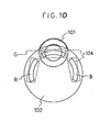
- the device using the monochrome CCD is, as shown in Fig. 9 and Fig. 10, composed of an optical lens mechanism 101 comprising a zoom lens arranged opposite to the film; a filter rotation disk 102 having color filters, a blue filter B, a green filter G and a red filter R, coaxially in the peripheral direction thereof; and a monochrome CCD 103.
- the light quantity of the respective filters B, G and R is balanced by applying a dark ND coating to the filter R to restrict the transmitting light quantity and a ND coating thinner than that to the filter G, with making the light voltage of the filter B to be a reference.
- the device using the monochrome CCD has been generally used, since it can obtain the necessary spectral characteristics freely by combining color filters.
- the film of the ND coating becomes a strong reflection surface, the reflected light on the surface of the monochrome CCD 103 is sometimes reflected by the film of the ND coating to be incident over the monochrome CCD 103.
- a phenomenon to degrade the contrast of the imaging plane of the monochrome CCD 103 (hereinafter referred to as a "flare") tends to be caused.
- the light reflected several times on the surface of the zoom lens reaches the film surface to generate an image being out of focus other than the regular image (hereinafter referred to as a "ghost”) tends to be generated.
- US Patent 4809198 describes a method for setting and managing photographic printing conditions of a photographic printing system, wherein monocolor red, green and blue light is generated, a recording material is exposed thereto, reference images with density steps are prepared, said densities of the three colour lights are measured, the measured densities are stored in a memory, amounts of exposure necessary for obtaining predetermined densities are determined, differences between said amounts of exposure and the reference amounts are obtained, and the amount of exposure for photographic printing is corrected in order to control the printing conditions.
- US 4942424 there is disclosed a colour photographic printing method of printing a colour film on the basis of a value of a light measuring device having a spectral sensitivity distribution which coincides with or is similar to a spectral sensitivity distribution of colour paper layers sensitive to red, green and blue.
- the method comprises the steps of calculating the film characteristics of a film to be printed, comparing the film characteristics of a reference film with that of the film to be printed, and correcting the printing condition of the reference film according to the result of the comparing step as well as calculating the amount of exposure for printing.
- JP-A-05063894 describes a picture reader provided with a photo electric conversion means with plural line sensors arranged at a tilt with respect to the optical axis of a read optical system. The purpose is to reduce the capacitance of a delay element by correcting any of the distances between object images among the plural line sensors with chromatic aberration of an image forming lens.
- JP-A-02150830 there is known a light measuring instrument for a photographic printer.
- colour filters are put in a printing optical path. Respective points of the image of a photographic film, which are projected through the colour filters are measured by an image sensor through a ND filter.
- JP-A-06250298 is a photographic printing/exposing controller. Its purpose is to adjust the exposure of each colour for an original image by means of the control of a colour filter and a shutter.
- the controller makes it unnecessary to use an optical shutter plate having special spectroscopic characteristics.
- the present invention has been completed under the above background and is defined by the appended claims 1-8. It is therefore a primary object of the present invention to provide an image reading device for photographic printing which can prevent the occurrence of the flare, ghost and color divergence and can obtain a clear color image.
- an image reading device for photographic printing comprising an optical lens mechanism, a monochrome CCD image device arranged at a focal position on an optical axis of the optical lens mechanism, a filter rotation plate having a plurality of color filters rotatably arranged on the optical axis, and a cut filter for blocking unnecessary light existing on the optical axis, characterized in that a light quantity correction means having a stepped spectral transmission filter characteristic over the spectral range of visible light is arranged on the optical axis.
- the image reading device for photographic printing of the invention by arranging the light quantity correction means on the optical axis instead of the ND coating applied to the color filters G and R, and by synthesizing the light quantity correction means and the cut filter, the reflected light due to the ND coating and the influences of the boundary plane and the parallel degrees of the cut filter and the color filter disappear, whereby the occurrence of flare, ghost and color divergence can be prevented. Furthermore, by tilting at least one of the cut filters and the light quantity correction means against the optical axis, the reflected light from the image-sensing plane of the monochrome CCD is not reflected to be incident over the image-sensing plane, and thus flare, ghost and color divergence can be further prevented.
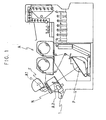
- the photographic printing device A which uses the image reading device for photographic printing of the present invention receives the light irradiated from a light source A1 via a mirror A2, reads the color image stored in the film F fed out from the negative mask N by the image reading device for the photographic printing, and, based on the read image information, performs printing to a photosensitive material P.
- the image reading device for photographic printing 1 comprises an optical lens mechanism 2, a monochrome CCD 3 arranged at a focal position of the optical axis L of the optical lens mechanism 2, a filter rotation plate (hereinafter referred to as "rotation plate") 5 having a plurality of color filters 4 rotatably arranged on the optical axis L, and a cut filter 6 for blocking unnecessary light existing on the optical axis L.
- rotation plate filter rotation plate
- the optical lens mechanism 2 is composed of, for example, a group of zoom lenses for enlarging the image stored in the film F.
- an inter line type CCD solid-state image sensing device can be used, although this is not particularly limited in the present invention.
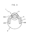
- the rotation plate 5 is in a disk-like form and the respective color filters 4 are housed in the rectangular holes 7 formed in the coaxial positions in the peripheral direction.
- the color filters 4 are a blue filter B, a green filter G and a red filter R in order.
- the driving device of the rotation plate 5 there can be used known motors, for example, a stepping motor and the like.
- the ND coating for restricting the amount of transmitting light is not applied to the filters G and R.
- the cut filter 6 is a filter to which a coating is applied to remove the ultraviolet rays and the infrared rays affecting the light quantity balance of the respective filters B, G and R.
- the image reading device for photographic printing according to the invention has the characteristic feature that a light quantity correction means S1 is arranged in front of the rotation plate 5 (on the right side of Fig. 1).
- the light quantity correction means S1 is, in the present embodiment, based in a front portion of the optical lens mechanism 2.
- This light quantity correction means S1 is arranged so that a stepped spectral characteristic can be obtained, as shown in Fig. 4, while different ND coatings are conventionally applied to the filters G and R, respectively, in order to obtain the sensitivity balance of the monochrome CCD by the respective filters B, G and R.
- the necessary spectral sensitivity can be obtained as a whole.
- the light quantity correction means S1 is such a means that a plurality of metal oxide films which balance the light quantity of the filters B, G and R are combined to be coated on the surface of the color balance filter comprising a transparent glass to obtain the stepped spectral characteristic.
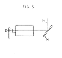
- a color balance mirror M for obtaining the stepwise reflective spectral characteristics as shown in Fig. 4 might be used on the optical axis L, instead of the mirror A2 shown in Fig. 1.
- the coating is applied by combining a plurality of metal oxide films as described above.
- flares can be reduced by arranging the light quantity correction means S1 in front of the optical lens mechanism 2.
- the light quantity correction means S1 is attached with being tilted by 5° or so against the optical axis L.
- the tilt angle of the color balance filter is made to be 5°, but it is not limited thereto, and can be properly selected in the range of, for example, from 5 to 10°, according to the image sensing area.
- the tilt direction is not particularly limited.
- the image reading device for photographic printing 11 has a light quantity correction means S2 different from the light quantity correction means S1 in the image reading device for photographic printing 1 in that the cut filter 6 and the light quantity correction means S1 are synthesized to make one filter.
- the coating to balance the light quantity of the respective filters B, G and R and the coating to remove the ultraviolet rays and infrared rays are applied on the back face and on the surface of one color balance filter 8, respectively.
- this color balance filter 8 is also arranged in front of the optical lens mechanism 12 and tilted by about 5° against the optical axis L, as described above.
- one sheet of color balance filter 8 integrally composed of the cut filter and the color balance filter is used.
- one cut filter 6 and a light quantity correction means S1 can be provided in parallel to be synthesized.
- the image reading device for photographic printing 11 of the present embodiment is not so affected by the parallel degree of respective filters B, G and R and the cut filter 6, compared to the image reading device for photographic printing 1, thereby flares and the like can be further prevented. Furthermore, by integrally synthesizing the cut filter and the color balance filter, the number of parts can be reduced to make the image reading device compact.
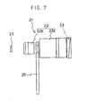
- the image reading device for photographic printing 21 is different from the image reading device for photographic printing 11 in that a rotation plate 25 is arranged within the lens group of the optical lens mechanism 22.
- the optical lens mechanism 22 is divided into the first lens mechanism 22a and the second lens mechanism 22b.
- the light quantity correction means S3 is arranged in front of the first lens mechanism 22a.
- the light quantity correction means S3 can integrally synthesize the cut filter and the color balance filter, or synthesize them in parallel, as in the light quantity correction means S2 in the image reading device for photographic printing 11. Furthermore, at least one of rotation plate 25 and the light quantity correction means S3 can be tilted against the optical axis.
- the image reading device for photographic printing 21 of the present embodiment has a rotation plate 25 arranged within the lens group of the optical lens mechanism 22. Therefore, the reflected light from the image sensing plane of the monochrome CCD 23 is not a parallel beam, whereby the reflected light is not reflected again on the monochrome CCD 23. As a result, the occurrence of flares and ghosts can be prevented.
- the image reading device for photographic printing 31 is different from the image reading device for photographic printing 11 in that the rotation plate 35 is arranged at a position ahead of the optical lens mechanism 32.
- the other features are identical with the image reading device for photographic printing 11.
- the position of the rotation plate 35 is not particularly limited in the present invention. Since the device is made compact, however, it is desired that the rotation plate should be arranged at a position apart from the optical lens mechanism 32 by, for example, 3 to 10 mm.
- the image reading device for photographic printing in the present invention is used to be mounted on the photographic printing device which reads the spectral data of the color image which is stored in the film and incident from the optical lens mechanism and respective filters B, G and R by rotating the rotor plate, then calculates the exposure conditions based on the data, and prints the image on the photosensitive material according to the conditions. Therefore, this printing device can obtain clear prints, while preventing flares, ghosts and the color divergence by the image reading device for photographic printing in the present invention.
- the image reading device for photographic printing of the invention by arranging the light quantity correction means having stepwise spectral characteristics on the optical axis, and by synthesizing the light quantity correction means and the cut filter, the reflected light due to the conventional ND coating and the influences of the boundary plane and the parallel degree between the cut filter and the color filter disappear. Thereby the occurrence of flare, ghost and color divergence can be prevented. Furthermore, by tilting at least one of the cut filter and the light quantity correction means against the optical axis, it is prevented that the reflected light from the image sensing plane of the monochrome CCD is reflected to be incident over the image sensing plane, whereby the occurrence of flare, ghost and color divergence can be further prevented. Furthermore, by integrally synthesizing the light quantity correction means and the cut filter, the number of parts can be reduced to make the image reading device compact.
- the occurrence of the color divergence can be further prevented.
Claims (8)
- Bildlesevorrichtung für den fotografischen Druck, mit einem optischen Linsenmechanismus (2, 12, 22, 32), einem in einer Fokusposition auf einer optischen Achse (L) des optischen Linsenmechanismus (2, 12, 22, 32) angeordneten monochromen CCD-Bildwandler (3, 23), einer Filterdrehplatte (5, 25, 35) mit einer Mehrzahl von Farbfiltern (4), die auf der optischen Achse (L) drehbar angeordnet sind, und einem Ausblendfilter (6) zum Ausblenden von unnötigem Licht, das sich auf der optischen Achse (L) befindet, dadurch gekennzeichnet, dass an der optischen Achse (L) eine Lichtmengenkorrektureinrichtung (S1, S2, S3) angeordnet ist, die über den Spektralbereich des sichtbaren Lichts eine Filtercharakteristik mit abgestuftem Spektraldurchlass aufweist, so dass die durch die Farbfilter (4) hindurchgelassene Lichtmenge ausgeglichen wird.
- Vorrichtung nach Anspruch 1, worin die Lichtmengenkorrektureinrichtung (S1, S2, S3) innerhalb des optischen Linsenmechanismus (2, 12, 22, 32) untergebracht ist.
- Vorrichtung nach Anspruch 1 oder 2, worin die Lichtmengenkorrektureinrichtung (S2) ein Farbausgleichsfilter (8) ist, bei dem auf einer Oberfläche eine Beschichtung zum Einschränken der durchgelassenen Lichtmenge aufgebracht ist.
- Vorrichtung nach Anspruch 1, worin die Lichtmengenkorrektureinrichtung (S1) ein Farbausgleichsspiegel (M) ist, bei dem auf eine Oberfläche eine Beschichtung zum Einschränken der Menge des durchgelassenen Lichts aufgebracht ist.
- Vorrichtung nach Anspruch 1 oder 2, worin die Lichtmengenkorrektureinrichtung und das Ausblendfilter synthetisiert sind.
- Vorrichtung nach Anspruch 1 oder 2, worin die Filterdrehplatte (25) innerhalb des optischen Linsenmechanismus (22) angeordnet ist.
- Vorrichtung nach Anspruch 1 oder 2, worin die Filterdrehplatte (35) vor dem optischen Linsenmechanismus (32) angeordnet ist.
- Vorrichtung nach Anspruch 1 oder 2, worin mindestens die Lichtmengenkorrektureinrichtung oder das Ausblendfilter gegen die optische Achse (L) geneigt ist.
Priority Applications (1)
| Application Number | Priority Date | Filing Date | Title |
|---|---|---|---|
| EP03020696A EP1382997A3 (de) | 1994-11-04 | 1995-10-28 | Bildlesevorrichtung für photographischen Druck |
Applications Claiming Priority (3)
| Application Number | Priority Date | Filing Date | Title |
|---|---|---|---|
| JP271257/94 | 1994-11-04 | ||
| JP27125794 | 1994-11-04 | ||
| JP27125794 | 1994-11-04 |
Related Child Applications (1)
| Application Number | Title | Priority Date | Filing Date |
|---|---|---|---|
| EP03020696A Division EP1382997A3 (de) | 1994-11-04 | 1995-10-28 | Bildlesevorrichtung für photographischen Druck |
Publications (2)
| Publication Number | Publication Date |
|---|---|
| EP0710875A1 EP0710875A1 (de) | 1996-05-08 |
| EP0710875B1 true EP0710875B1 (de) | 2003-09-17 |
Family
ID=17497556
Family Applications (2)
| Application Number | Title | Priority Date | Filing Date |
|---|---|---|---|
| EP03020696A Withdrawn EP1382997A3 (de) | 1994-11-04 | 1995-10-28 | Bildlesevorrichtung für photographischen Druck |
| EP95117017A Expired - Lifetime EP0710875B1 (de) | 1994-11-04 | 1995-10-28 | Bildlesevorrichtung für photographischen Druck |
Family Applications Before (1)
| Application Number | Title | Priority Date | Filing Date |
|---|---|---|---|
| EP03020696A Withdrawn EP1382997A3 (de) | 1994-11-04 | 1995-10-28 | Bildlesevorrichtung für photographischen Druck |
Country Status (6)
| Country | Link |
|---|---|
| US (1) | US6023350A (de) |
| EP (2) | EP1382997A3 (de) |
| KR (1) | KR100261373B1 (de) |
| CN (1) | CN1077297C (de) |
| CA (1) | CA2161709C (de) |
| DE (1) | DE69531760T2 (de) |
Families Citing this family (7)
| Publication number | Priority date | Publication date | Assignee | Title |
|---|---|---|---|---|
| US6118598A (en) * | 1999-04-13 | 2000-09-12 | Hewlett-Packard Company | Method and apparatus for setting focus in an imaging device |
| JP2001105659A (ja) * | 1999-10-07 | 2001-04-17 | Fuji Photo Film Co Ltd | 光学式プリンタ及びプリント方法 |
| US6897432B2 (en) | 2001-03-20 | 2005-05-24 | Hewlett-Packard Development Company, L.P. | Imaging apparatus having discontinuous lens reference surfaces and method of assembling the imaging apparatus |
| US20030197116A1 (en) * | 2002-04-18 | 2003-10-23 | David A. Novais, Eastman Kodak Company | Combination shutter and attenuator disk for an imaging apparatus |
| US7755676B2 (en) * | 2002-08-30 | 2010-07-13 | Fujifilm Corporation | Multi-band image photographing method and apparatus, and program for executing the method |
| JP6884514B2 (ja) * | 2015-04-28 | 2021-06-09 | 株式会社デンソーウェーブ | 光学的情報読取装置 |
| EP3185534B1 (de) | 2015-12-23 | 2020-02-12 | Robert Bosch Gmbh | Kameravorrichtung mit roter haloreduktion |
Family Cites Families (22)
| Publication number | Priority date | Publication date | Assignee | Title |
|---|---|---|---|---|
| GB2060962A (en) * | 1979-07-12 | 1981-05-07 | Thorn Electrical Ind Ltd | Lighting unit for glide path landing |
| US4466725A (en) * | 1982-04-16 | 1984-08-21 | Canon Kabushiki Kaisha | Electromagnetic drive device for camera |
| JPS60146567A (ja) * | 1984-01-10 | 1985-08-02 | Sharp Corp | カラ−画像読取装置 |
| JPH0646811B2 (ja) * | 1984-08-31 | 1994-06-15 | オリンパス光学工業株式会社 | カラ−撮像装置の照明装置 |
| JPS61232763A (ja) * | 1985-04-09 | 1986-10-17 | Dainippon Screen Mfg Co Ltd | 複写光学系の光量ムラ補正装置 |
| JPS6276857A (ja) * | 1985-09-30 | 1987-04-08 | Ricoh Co Ltd | カラ−原稿読取装置 |
| JPH0640194B2 (ja) * | 1985-10-15 | 1994-05-25 | 富士写真フイルム株式会社 | 写真焼付条件の設定管理方法 |
| JP2679014B2 (ja) * | 1986-03-19 | 1997-11-19 | オリンパス光学工業株式会社 | 電子内視鏡装置 |
| US4786964A (en) * | 1987-02-02 | 1988-11-22 | Polaroid Corporation | Electronic color imaging apparatus with prismatic color filter periodically interposed in front of an array of primary color filters |
| US4875074A (en) * | 1987-04-01 | 1989-10-17 | Brother Kogyo Kabushiki Kaisha | Image recording apparatus |
| US4942424A (en) * | 1987-06-12 | 1990-07-17 | Fuji Photo Film Co., Ltd. | Method of and apparatus for printing color photograph as well as color filter for use in the same apparatus |
| US5075768A (en) * | 1988-09-02 | 1991-12-24 | Itek Graphix Corporation | Method and apparatus for color separation scanning |
| US4933779A (en) * | 1988-09-08 | 1990-06-12 | Eastman Kodak Company | Image scanner apparatus of the drum type having an efficient line-of-light illumination system |
| JPH02150830A (ja) * | 1988-12-01 | 1990-06-11 | Fuji Photo Film Co Ltd | 写真プリンタの測光装置 |
| US5033821A (en) * | 1989-10-24 | 1991-07-23 | Asahi Kogaku Kogyo Kabushiki Kaisha | Element selecting device |
| JPH04116433A (ja) * | 1990-09-06 | 1992-04-16 | Hitachi Ltd | 放射温度計および該温度計による温度測定方法 |
| JPH0830857B2 (ja) * | 1990-11-13 | 1996-03-27 | 富士ゼロックス株式会社 | 複写方法 |
| DE4110813A1 (de) * | 1991-04-04 | 1992-10-08 | Agfa Gevaert Ag | Verfahren zum punkt- und zeilenweisen kopieren einer kopiervorlage |
| JP3227191B2 (ja) * | 1991-05-22 | 2001-11-12 | 株式会社リコー | 画像読取装置 |
| JPH0563894A (ja) * | 1991-08-29 | 1993-03-12 | Toshiba Corp | 画像読取装置 |
| US5337164A (en) * | 1992-01-30 | 1994-08-09 | Konica Corporation | Negative film image reading device |
| JPH06250298A (ja) * | 1993-02-26 | 1994-09-09 | Konica Corp | 写真焼付露光制御装置 |
-
1995
- 1995-10-28 EP EP03020696A patent/EP1382997A3/de not_active Withdrawn
- 1995-10-28 DE DE69531760T patent/DE69531760T2/de not_active Expired - Fee Related
- 1995-10-28 EP EP95117017A patent/EP0710875B1/de not_active Expired - Lifetime
- 1995-10-30 CA CA002161709A patent/CA2161709C/en not_active Expired - Fee Related
- 1995-10-31 US US08/551,140 patent/US6023350A/en not_active Expired - Fee Related
- 1995-11-03 CN CN95118752A patent/CN1077297C/zh not_active Expired - Fee Related
- 1995-11-03 KR KR1019950039550A patent/KR100261373B1/ko not_active IP Right Cessation
Also Published As
| Publication number | Publication date |
|---|---|
| DE69531760D1 (de) | 2003-10-23 |
| EP1382997A2 (de) | 2004-01-21 |
| KR100261373B1 (ko) | 2000-07-01 |
| US6023350A (en) | 2000-02-08 |
| CN1130264A (zh) | 1996-09-04 |
| CN1077297C (zh) | 2002-01-02 |
| CA2161709C (en) | 2000-07-18 |
| KR960018643A (ko) | 1996-06-17 |
| CA2161709A1 (en) | 1996-05-05 |
| EP0710875A1 (de) | 1996-05-08 |
| EP1382997A3 (de) | 2007-04-25 |
| DE69531760T2 (de) | 2004-07-01 |
Similar Documents
| Publication | Publication Date | Title |
|---|---|---|
| US5162841A (en) | Exposure controlling apparatus | |
| US4942424A (en) | Method of and apparatus for printing color photograph as well as color filter for use in the same apparatus | |
| EP0710875B1 (de) | Bildlesevorrichtung für photographischen Druck | |
| US7050205B2 (en) | Method of correcting image data picked up from photographic film | |
| US4929971A (en) | Camera and image output apparatus capable of trimmed photographing | |
| US3698809A (en) | Automatic illumination control for photographic printing apparatus | |
| US5497229A (en) | Photometering apparatus having a split light receiving device | |
| JP3248409B2 (ja) | 写真焼付用画像読取り装置 | |
| JPH02149802A (ja) | ネガフィルム測定装置および自動カラー写真焼付装置 | |
| US5760882A (en) | Contact printer and method of making a filter for a contact printer | |
| CA2289323A1 (en) | Image reading device for photographic printing | |
| JPH0627551A (ja) | 露光装置 | |
| US5856864A (en) | Photographic printer and method of making a filter for a photographic printer | |
| JPH05173004A (ja) | Ndフィルタの製造方法と絞り装置 | |
| US5463445A (en) | Method and apparatus for image photometering | |
| US7292376B2 (en) | Device for digitally generating images | |
| JP3248600B2 (ja) | 画像装置 | |
| JPH0583477A (ja) | カラー分離スキヤナー | |
| JPS63177650A (ja) | 画像読取・記録装置 | |
| JPH04319933A (ja) | 写真焼付方法 | |
| JP2547864B2 (ja) | 露光制御装置 | |
| JP2599475B2 (ja) | 露光制御装置 | |
| JPS63285524A (ja) | トリミング撮影に適した撮影装置 | |
| JP2644232B2 (ja) | カラー複写機の露光装置 | |
| JP2725083B2 (ja) | 画像読取方法 |
Legal Events
| Date | Code | Title | Description |
|---|---|---|---|
| PUAI | Public reference made under article 153(3) epc to a published international application that has entered the european phase |
Free format text: ORIGINAL CODE: 0009012 |
|
| AK | Designated contracting states |
Kind code of ref document: A1 Designated state(s): CH DE FR GB IT LI |
|
| 17P | Request for examination filed |
Effective date: 19960614 |
|
| 17Q | First examination report despatched |
Effective date: 20020306 |
|
| GRAH | Despatch of communication of intention to grant a patent |
Free format text: ORIGINAL CODE: EPIDOS IGRA |
|
| GRAS | Grant fee paid |
Free format text: ORIGINAL CODE: EPIDOSNIGR3 |
|
| GRAA | (expected) grant |
Free format text: ORIGINAL CODE: 0009210 |
|
| AK | Designated contracting states |
Kind code of ref document: B1 Designated state(s): CH DE FR GB IT LI |
|
| PG25 | Lapsed in a contracting state [announced via postgrant information from national office to epo] |
Ref country code: LI Free format text: LAPSE BECAUSE OF FAILURE TO SUBMIT A TRANSLATION OF THE DESCRIPTION OR TO PAY THE FEE WITHIN THE PRESCRIBED TIME-LIMIT Effective date: 20030917 Ref country code: IT Free format text: LAPSE BECAUSE OF FAILURE TO SUBMIT A TRANSLATION OF THE DESCRIPTION OR TO PAY THE FEE WITHIN THE PRE;WARNING: LAPSES OF ITALIAN PATENTS WITH EFFECTIVE DATE BEFORE 2007 MAY HAVE OCCURRED AT ANY TIME BEFORE 2007. THE CORRECT EFFECTIVE DATE MAY BE DIFFERENT FROM THE ONE RECORDED.SCRIBED TIME-LIMIT Effective date: 20030917 Ref country code: CH Free format text: LAPSE BECAUSE OF FAILURE TO SUBMIT A TRANSLATION OF THE DESCRIPTION OR TO PAY THE FEE WITHIN THE PRESCRIBED TIME-LIMIT Effective date: 20030917 |
|
| REG | Reference to a national code |
Ref country code: GB Ref legal event code: FG4D Free format text: NOT ENGLISH |
|
| REG | Reference to a national code |
Ref country code: CH Ref legal event code: EP |
|
| REG | Reference to a national code |
Ref country code: GB Ref legal event code: FG4C Free format text: NOTIFICATION HAS BEEN RECEIVED FROM THE EUROPEAN PATENT OFFICE THAT THE PUBLICATION LANGUAGE IS ACTUALLY ENGLISH. |
|
| REF | Corresponds to: |
Ref document number: 69531760 Country of ref document: DE Date of ref document: 20031023 Kind code of ref document: P |
|
| REG | Reference to a national code |
Ref country code: CH Ref legal event code: PL |
|
| ET | Fr: translation filed | ||
| PLBE | No opposition filed within time limit |
Free format text: ORIGINAL CODE: 0009261 |
|
| STAA | Information on the status of an ep patent application or granted ep patent |
Free format text: STATUS: NO OPPOSITION FILED WITHIN TIME LIMIT |
|
| 26N | No opposition filed |
Effective date: 20040618 |
|
| PGFP | Annual fee paid to national office [announced via postgrant information from national office to epo] |
Ref country code: FR Payment date: 20041008 Year of fee payment: 10 |
|
| PGFP | Annual fee paid to national office [announced via postgrant information from national office to epo] |
Ref country code: GB Payment date: 20041027 Year of fee payment: 10 |
|
| PGFP | Annual fee paid to national office [announced via postgrant information from national office to epo] |
Ref country code: DE Payment date: 20051020 Year of fee payment: 11 |
|
| PG25 | Lapsed in a contracting state [announced via postgrant information from national office to epo] |
Ref country code: GB Free format text: LAPSE BECAUSE OF NON-PAYMENT OF DUE FEES Effective date: 20051028 |
|
| GBPC | Gb: european patent ceased through non-payment of renewal fee |
Effective date: 20051028 |
|
| PG25 | Lapsed in a contracting state [announced via postgrant information from national office to epo] |
Ref country code: FR Free format text: LAPSE BECAUSE OF NON-PAYMENT OF DUE FEES Effective date: 20060630 |
|
| REG | Reference to a national code |
Ref country code: FR Ref legal event code: ST Effective date: 20060630 |
|
| PG25 | Lapsed in a contracting state [announced via postgrant information from national office to epo] |
Ref country code: DE Free format text: LAPSE BECAUSE OF NON-PAYMENT OF DUE FEES Effective date: 20070501 |