EP0710540B1 - Verfahren und Vorrichtung zur Herstellung eines optischen Gegenstands - Google Patents
Verfahren und Vorrichtung zur Herstellung eines optischen Gegenstands Download PDFInfo
- Publication number
- EP0710540B1 EP0710540B1 EP95116861A EP95116861A EP0710540B1 EP 0710540 B1 EP0710540 B1 EP 0710540B1 EP 95116861 A EP95116861 A EP 95116861A EP 95116861 A EP95116861 A EP 95116861A EP 0710540 B1 EP0710540 B1 EP 0710540B1
- Authority
- EP
- European Patent Office
- Prior art keywords
- optical material
- mold
- optical
- temperature
- found
- Prior art date
- Legal status (The legal status is an assumption and is not a legal conclusion. Google has not performed a legal analysis and makes no representation as to the accuracy of the status listed.)
- Expired - Lifetime
Links
Images


Classifications
-
- B—PERFORMING OPERATIONS; TRANSPORTING
- B29—WORKING OF PLASTICS; WORKING OF SUBSTANCES IN A PLASTIC STATE IN GENERAL
- B29D—PRODUCING PARTICULAR ARTICLES FROM PLASTICS OR FROM SUBSTANCES IN A PLASTIC STATE
- B29D11/00—Producing optical elements, e.g. lenses or prisms
- B29D11/00009—Production of simple or compound lenses
- B29D11/0048—Moulds for lenses
- B29D11/00528—Consisting of two mould halves joined by an annular gasket
-
- B—PERFORMING OPERATIONS; TRANSPORTING
- B29—WORKING OF PLASTICS; WORKING OF SUBSTANCES IN A PLASTIC STATE IN GENERAL
- B29C—SHAPING OR JOINING OF PLASTICS; SHAPING OF MATERIAL IN A PLASTIC STATE, NOT OTHERWISE PROVIDED FOR; AFTER-TREATMENT OF THE SHAPED PRODUCTS, e.g. REPAIRING
- B29C43/00—Compression moulding, i.e. applying external pressure to flow the moulding material; Apparatus therefor
- B29C43/02—Compression moulding, i.e. applying external pressure to flow the moulding material; Apparatus therefor of articles of definite length, i.e. discrete articles
-
- B—PERFORMING OPERATIONS; TRANSPORTING
- B29—WORKING OF PLASTICS; WORKING OF SUBSTANCES IN A PLASTIC STATE IN GENERAL
- B29C—SHAPING OR JOINING OF PLASTICS; SHAPING OF MATERIAL IN A PLASTIC STATE, NOT OTHERWISE PROVIDED FOR; AFTER-TREATMENT OF THE SHAPED PRODUCTS, e.g. REPAIRING
- B29C43/00—Compression moulding, i.e. applying external pressure to flow the moulding material; Apparatus therefor
- B29C43/32—Component parts, details or accessories; Auxiliary operations
- B29C43/36—Moulds for making articles of definite length, i.e. discrete articles
- B29C43/361—Moulds for making articles of definite length, i.e. discrete articles with pressing members independently movable of the parts for opening or closing the mould, e.g. movable pistons
-
- B—PERFORMING OPERATIONS; TRANSPORTING
- B29—WORKING OF PLASTICS; WORKING OF SUBSTANCES IN A PLASTIC STATE IN GENERAL
- B29C—SHAPING OR JOINING OF PLASTICS; SHAPING OF MATERIAL IN A PLASTIC STATE, NOT OTHERWISE PROVIDED FOR; AFTER-TREATMENT OF THE SHAPED PRODUCTS, e.g. REPAIRING
- B29C43/00—Compression moulding, i.e. applying external pressure to flow the moulding material; Apparatus therefor
- B29C43/32—Component parts, details or accessories; Auxiliary operations
- B29C43/58—Measuring, controlling or regulating
-
- B—PERFORMING OPERATIONS; TRANSPORTING
- B29—WORKING OF PLASTICS; WORKING OF SUBSTANCES IN A PLASTIC STATE IN GENERAL
- B29D—PRODUCING PARTICULAR ARTICLES FROM PLASTICS OR FROM SUBSTANCES IN A PLASTIC STATE
- B29D11/00—Producing optical elements, e.g. lenses or prisms
- B29D11/00009—Production of simple or compound lenses
- B29D11/00038—Production of contact lenses
- B29D11/00057—Production of contact lenses characterised by the shape or surface condition of the edge, e.g. flashless, burrless, smooth
-
- B—PERFORMING OPERATIONS; TRANSPORTING
- B29—WORKING OF PLASTICS; WORKING OF SUBSTANCES IN A PLASTIC STATE IN GENERAL
- B29D—PRODUCING PARTICULAR ARTICLES FROM PLASTICS OR FROM SUBSTANCES IN A PLASTIC STATE
- B29D11/00—Producing optical elements, e.g. lenses or prisms
- B29D11/00009—Production of simple or compound lenses
- B29D11/00413—Production of simple or compound lenses made by moulding between two mould parts which are not in direct contact with one another, e.g. comprising a seal between or on the edges
-
- B—PERFORMING OPERATIONS; TRANSPORTING
- B29—WORKING OF PLASTICS; WORKING OF SUBSTANCES IN A PLASTIC STATE IN GENERAL
- B29C—SHAPING OR JOINING OF PLASTICS; SHAPING OF MATERIAL IN A PLASTIC STATE, NOT OTHERWISE PROVIDED FOR; AFTER-TREATMENT OF THE SHAPED PRODUCTS, e.g. REPAIRING
- B29C43/00—Compression moulding, i.e. applying external pressure to flow the moulding material; Apparatus therefor
- B29C43/32—Component parts, details or accessories; Auxiliary operations
- B29C43/36—Moulds for making articles of definite length, i.e. discrete articles
- B29C43/361—Moulds for making articles of definite length, i.e. discrete articles with pressing members independently movable of the parts for opening or closing the mould, e.g. movable pistons
- B29C2043/3615—Forming elements, e.g. mandrels or rams or stampers or pistons or plungers or punching devices
- B29C2043/3618—Forming elements, e.g. mandrels or rams or stampers or pistons or plungers or punching devices plurality of counteracting elements
-
- B—PERFORMING OPERATIONS; TRANSPORTING
- B29—WORKING OF PLASTICS; WORKING OF SUBSTANCES IN A PLASTIC STATE IN GENERAL
- B29C—SHAPING OR JOINING OF PLASTICS; SHAPING OF MATERIAL IN A PLASTIC STATE, NOT OTHERWISE PROVIDED FOR; AFTER-TREATMENT OF THE SHAPED PRODUCTS, e.g. REPAIRING
- B29C43/00—Compression moulding, i.e. applying external pressure to flow the moulding material; Apparatus therefor
- B29C43/02—Compression moulding, i.e. applying external pressure to flow the moulding material; Apparatus therefor of articles of definite length, i.e. discrete articles
- B29C43/021—Compression moulding, i.e. applying external pressure to flow the moulding material; Apparatus therefor of articles of definite length, i.e. discrete articles characterised by the shape of the surface
-
- B—PERFORMING OPERATIONS; TRANSPORTING
- B29—WORKING OF PLASTICS; WORKING OF SUBSTANCES IN A PLASTIC STATE IN GENERAL
- B29L—INDEXING SCHEME ASSOCIATED WITH SUBCLASS B29C, RELATING TO PARTICULAR ARTICLES
- B29L2011/00—Optical elements, e.g. lenses, prisms
- B29L2011/0016—Lenses
-
- Y—GENERAL TAGGING OF NEW TECHNOLOGICAL DEVELOPMENTS; GENERAL TAGGING OF CROSS-SECTIONAL TECHNOLOGIES SPANNING OVER SEVERAL SECTIONS OF THE IPC; TECHNICAL SUBJECTS COVERED BY FORMER USPC CROSS-REFERENCE ART COLLECTIONS [XRACs] AND DIGESTS
- Y10—TECHNICAL SUBJECTS COVERED BY FORMER USPC
- Y10S—TECHNICAL SUBJECTS COVERED BY FORMER USPC CROSS-REFERENCE ART COLLECTIONS [XRACs] AND DIGESTS
- Y10S425/00—Plastic article or earthenware shaping or treating: apparatus
- Y10S425/808—Lens mold
Definitions
- This invention relates to an optical elements, a method and a device for manufacturing high precision optical elements such as a lens, prism and mirror used in optical instruments.
- US-A-2304217 refers to a method and apparatus for making lenses in accordance with the preamble of claims 1 and 7 using a casing which covers around a top mold, a bottom mold and a sleeve. While material to be molded is heated and pressurized by the top mold and the bottom mold, a high pressure is applied around the top mold, the bottom mold and the sleeve. Consequently, the generation of gas from the material to be molded can be prevented.
- Conventional press-molding methods for optical elements include, for example, an injection molding method and a compression molding method (Published Unexamined (Kokai) Japanese Patent Application No. Hei 5-177725).
- a pellet is injected and filled in a cavity, formed by an insert, after heating, kneading and melting the pellet.
- a plastic material which is molded in a final shape by the injection molding method is placed in a mold kept at a certain temperature, and then is compressed.
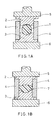
- Fig. 11 shows a conventional molding method.
- 27 is an optical element
- 28 is a top mold
- 29 is a bottom mold
- 30 is a drum mold
- 31 is a section of a press head including a heat pressing mechanism
- 32 is a section of a press stage having a heating mechanism.
- Fig. 12A and Fig. 12B show changes in temperature and pressure in the conventional molding method.
- Fig. 12A shows the temperature of the optical element.
- Fig. 12B indicates the pressure by the press head.
- An optical element (polycarbonate) which was molded into a final shape by the injection molding method is placed in a cavity consisting of top mold 28, bottom mold 29, and drum 30.
- the temperature of the top mold, the bottom mold and the drum mold is set higher than a deflection temperature (measured by D648 (ATM)) and lower than the glass transition point.
- ATM deflection temperature
- press head 31 is lowered.
- the element is molded under extremely high pressure, so that the optical material enters clearance sections between the top mold or the bottom mold and the drum mold.
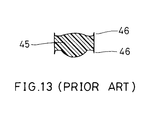
- molded optical element 45 is formed with burr (46 in Fig. 13).
- Optical elements formed with such a burr result in uneven properties and mounting problems for instruments. Therefore, the optical elements with a burr have to be worked to remove the burr. Moreover, burr remaining on the top, bottom and drum mold also has to be removed. As a result, the cost of manufacturing optical elements becomes high.
- the optical elements molded by the conventional injection molding method have gate cut sections. As the temperature of optical elements during molding increases, concave sections are formed at the gate cut sections. The concave section remains on the optically functional area of an optical element. In other words, the optical elements formed in this method have poor shape and optical properties, and inferior yields.
- the gate cut sections are sections where resin is cut at a gate section.
- the gate section is an opening where resin is injected into the cavity of a mold during injection molding processes. Since resin is cut after being injected into the gate section, internal stress is likely to remain and concentrate in a section of the resin, thus forming a defect such as a strain.
- the method of manufacturing optical elements of this invention includes the steps of depositing an optical material, which was already roughly molded, into a space defined by a top mold, a bottom mold and a drum mold and of heating and pressing the optical material.
- the speed Vp of the press head of the optical material is controlled so as to prevent the material from flowing into clearance sections between the outside diameter of the top mold and the inside diameter of the drum mold, and between the outside diameter of the bottom mold and the inside diameter of the drum mold.
- the rate of plastic deformation of the optical material is controlled to less than 10mm/second at least during the final deformation process and the temperature is maintained at (Tg+15) ⁇ Tp ⁇ (Tg+60) during the molding process of an optical material, where Tp is the maximum temperature of the optical material and Tg is the glass transition point of resin of the optical material.
- the optical material is pressed and deformed with 1.5-25.0kgf/cm 2 pressure in a range from the glass transition point (Tg) to the maximum temperature (Tp).
- the optical material is preliminarily deformed until the material reaches the maximum temperature (Tp), and that the material is pressed with 1.5-25.0kgf/cm 2 pressure while being cooled from Tp to the glass transition point (Tg).
- the optical material is roughly molded by an injection molding method before the deformation process.
- the optical material has a gate cut section formed during the injection molding processes, and that the gate cut section is convex.
- the optical mterial which was already roughly molded, has a gate cut section, and that the material is deposited so that the gate cut section faces the internal surface of a drum mold or the moving side of a pressing means.
- the optical elements of this invention are prepared by a method of manufacturing optical elements comprising the steps of: depositing an optical material, which was already roughly molded, into a space defined by a top mold, a bottom mold and a drum mold; and heating and pressing the optical material; wherein the speed Vp of the press head of the optical material is controlled to less than 10mm/second at least during a final deformation process so as to prevent the optical material from flowing into clearance sections between an outside diameter of the top mold or of the bottom mold and an inside diameter of the drum mold and the optical material is heated during molding to a maximum temperature (Tp), with (Tg+15) ⁇ Tp ⁇ (Tg+60) wherein Tg is the glass transition temperature of the optical material.
- Tp maximum temperature
- the element is a lens for use in optical instruments.
- the element is a prism for use in optical instruments.
- the element is a mirror for use in optical instruments.
- the device for manufacturing optical elements of this invention includes a top mold, a bottom mold, a drum mold, and a means to control the speed Vp of the press head of optical material.
- the device heats, presses and molds optical material after the material is deposited into a space between the top, bottom and drum molds.
- the means to control the speed Vp of the press head of the optical material prevents the material from flowing into clearance sections between the outside diameter of the top mold and the inside diameter of the drum mold, and between the outside diameter of the bottom mold and the inside diameter of the drum mold.
- the rate of plastic deformation of the optical mold is controlled to less than 10mm/second by the means and the device further includes a means to maintain temperature at (Tg+15) ⁇ Tp ⁇ (Tg+60) during the molding process of an optical material, where Tp is the maximum temperature of the optical material and Tg is the glass transition point of resin of the optical material.
- the device further includes a means to deform optical material with 1.5-25.0kgf/cm 2 of pressure within a range between the glass transition point (Tg) and the maximum temperature (Tp).
- the device further includes a means to preliminarily deform optical material until the material reaches the maximum temperature (Tp) and a means to deform the material with 1.5-25.0kgf/cm 2 pressure while the material is cooled from Tp to the glass transition point (Tg).
- Tp maximum temperature
- Tg glass transition point
- the device further includes a means to deposit optical material into a space between the top, bottom and drum molds so that the gate cut section of the optical material faces the internal surface of the drum mold and the moving side of a pressing means.
- Optical material enters a clearance section among a top mold, a bottom mold, and a drum mold when the rate of plastic deformation of the material is faster than a certain rate.
- the rate of plastic deformation is controlled by setting the lowering speed of a press head, optical material temperature, and press pressure.
- Tg+15) ⁇ Tp ⁇ (Tg+60) during the molding process of an optical material, where Tp is the maximum temperature and Tg is the glass transition point of the optical material, and pressure is added up to temperature lower than the deflection temperature, so that the transfer surface of the top or bottom mold is transferred onto optical material at high precision and an optical element with preferable optical properties is provided.
- the deflection temperature is measured by D648 (ASTM).
- a means is applied in this invention which leaves a gate cut section of an optical material, preliminary molded by an injection method, in a convex form, thus preventing the gate cut section from becoming concave even when the temperature of the optical material increases during a pressing and molding process.
- an optical element having no burr is manufactured in this invention, so that a process for removing the burr is not required.
- productivity of optical elements improves, and the cost of the elements is reduced.
- a strain is unlikely to remain inside an optical element, so that an optical element such as a thin lens having a small diameter is molded.
- a preferable optical element is provided without being dependent on the direction of supply of the material.
- the yield of optical elements improves, and the cost of manufacturing the elements is reduced.
- Fig. 1A is a cross-sectional view showing an optical material of one embodiment of the invention before being molded.
- Fig. 1B is a cross-sectional view showing the optical material of the embodiment of the invention after being molded.
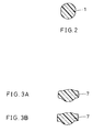
- Fig. 2 is a cross-sectional view of an optical material of the embodiment of the invention.
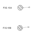
- Fig. 3A is a cross-sectional view of an optical element of the embodiment of the invention.
- Fig. 3B is a cross-sectional view of an optical element of the embodiment of the invention.
- Fig. 4 is a graph showing the no burr-generating molding conditions range of the embodiment of the invention.
- Fig. 5A is a graph showing the change in temperature of an optical element during a molding process of another embodiment of the invention.
- Fig. 5B is a graph showing the change in pressure during the molding process of the embodiment of the invention.
- Fig. 5C is a graph showing the rate of plastic deformation during the molding process of the embodiment of the invention.
- Fig. 6A is a cross-sectional view showing the gate cut section of the optical material of the embodiment of the invention facing the inside surface of a drum mold.
- Fig. 6B is a cross-sectional view showing the gate cut section of the optical material of the embodiment of the invention facing a press head.
- Fig. 6C is a cross-sectional view showing the gate cut section of the optical material of the embodiment of the invention facing a press stage.
- Fig. 7A is a cross-sectional view of an optical material with a gate cut section of another embodiment of the invention molded by the injection molding method.
- Fig. 7B is a cross-sectional view of the optical material with a gate cut section of the embodiment of the invention after being heated.
- Fig. 8A is a graph showing the change in temperature of the optical element of the embodiment of the molding method of the invention during a molding process.
- Fig. 8B is a graph showing the change in pressure of the optical element.
- Fig. 8C is a graph showing plastic deformation of the optical element.
- Fig. 9A is a cross-sectional view showing a heating process of the embodiment of the molding method of the invention.
- Fig. 9B is a cross-sectional view showing a preliminary deformation step of the embodiment of the molding method of the invention.
- Fig. 9C is a cross-sectional view showing a final deformation step of the embodiment of the molding method of the invention.
- Fig. 9D is a cross-sectional view showing a cooling process of the embodiment of the molding method of the invention.
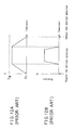
- Fig. 10A is a cross-sectional view of an optical material with a gate cut section of the embodiment of the invention molded by the injection molding method.
- Fig. 10B is a cross-sectional view of the optical material with a gate cut section of the embodiment of the invention after being heated.
- Fig. 11 is a cross-sectional view showing an optical material being pressed and deformed by a conventional molding method.
- Fig. 12A shows the change in temperature of the optical material applied in the conventional method.
- Fig. 12B shows the change in pressure in the conventional method.
- Fig. 13 is a cross-sectional view of an optical element with burr molded by the conventional molding method.
- Fig. 1A is a cross-sectional view of an optical material before being molded.
- Fig. 1B is a cross-sectional view of the optical material after being molded.
- optical material 1 is placed in the space defined by top mold 2, bottom mold 3, and drum mold 4, and between press head 5 and press stage 6.
- a polyolefin resin (a trade mark "ZEONEX”, Nippon Zeon Co., Ltd. 140°C glass transition point Tg, and 123°C deflection temperature Tt) block is cut and worked so as to provide optical material 1 with 2.5mm Rs and 4.675mm central thickness (t) as shown in Fig. 2.
- Cemented carbide was used for top mold 2, bottom mold 3 and drum mold 4, and was worked into preferable shapes.
- the clearance between the outside diameter of top mold 2 or of bottom mold 3 and the inside diameter of drum mold 4 is about 5 ⁇ m.
- Optical element 7 roughly has 2.9mm R1, 4.6mm R2, 3.2mm central thickness (t), and 5.0mm outside diameter.
- Optical material 1 is heated to 170°C Tp (predetermined temperature) by press head 5 and press stage 6 for ten minutes.
- Tp predetermined temperature
- press head 5 is advanced at 0.1mm/sec Vp, and optical material 1 is deformed by top mold 2.
- the speed Vp of press head 5 is the rate of plastic deformation (Vp) of the optical material.
- Press head 5 stops lowering as soon as drum mold 4 is in contact with top mold 2.
- deformed optical material 1 After being kept at predetermined temperature Tp for ten minutes, deformed optical material 1 is cooled down to deflection temperature (Tt) for ten minutes while press head 5 is advancing. Press head 5 and top mold 2 are opened, and optical element 7 is then taken out. When the pressure is removed before the temperature reaches the deflection temperature, the optical material recovers elastically. Thus, the transfer precision of the material deteriorates. With the temperature below the deflection temperature (Tt), press head 5 is released, and top mold 2 is opened so as to remove optical element 7. Under conditions of 170°C Tp (maximum temperature) and 3.5kgf/cm 2 pressure (P), an optical element was provided. The optical element had no burr shown in Fig. 3A, and had a desirable transmitted wave area and a preferable central thickness. The rate of plastic deformation of the optical material was 0.1mm/sec.
- Optical element 7 has no burr as shown in Fig. 3A since no optical material 1 enters the clearance between the outside diameter of top mold 2 or bottom mold 3 and the inside diameter of drum mold 4.
- Fig. 4 is a graph showing the correlations between predetermined temperature Tp and the speed Vp of the press head and indicating the range of generating no burr.
- the horizontal axis indicates maximum temperature Tp of the optical material during the molding process while the vertical axis indicates the rate of plastic deformation Vp of the optical material.
- no burr is generated when maximum temperature Tp and the speed Vp of the press head are controlled.
- An optical element shown in Fig. 3A is provided when the Tp maximum temperature is in a range between a Tt deflection temperature and a Tg+40°C glass transition point, and the rate of plastic deformation was below 10mm/sec. With a Tp maximum temperature in a range between Tg+40°C glass transition point and Tg+60°C glass transition point, an optical element shown in Fig. 3B is obtained.
- the optical element shown in Fig. 3B has no burr, but has sections which almost reached the clearance section.
- Tp maximum temperature is preferably in the range between Tt deflection temperature and Tg+40°C glass transition point.
- Tp maximum temperature is in another range
- a burr is found on optical elements as shown in Fig. 13 (45 indicates the burr).
- Tp predetermined temperature below Tt deflection temperature
- the optical element does not deform since the temperature is in the range of elastic deformation. If pressure is added to an optical material forcibly, the optical element with a crack is provided.
- an optical material melts and deforms while the rate of plastic deformation of the optical material is not dependent on the lowering speed of a press head. Furthermore, the optical material enters a clearance section between the outside diameter of a top mold or a bottom mold and the inside diameter of a drum mold, thus forming a burr.
- the rate of plastic deformation of an optical material is controlled by the advancind speed of a press head in this example, it may be controlled by temperature, pressure or the like.
- optical materials which are mass produced by the injection molding method with small cost may be used.
- the same results are expected from another optical material such as thermoplastic resin (polycarbonate (PC), polymethyl methacrylate (PMMA), and the like).
- the heating time up to temperature Tp, the time at temperature Tp, and the cooling time from temperature Tp to the deflection temeprature are not limited to the ones mentioned above.
- An optical element can be removed from the mold as long as the optical element temperature is less than the deflection temperature.
- the material of the top, bottom and drum mold is not limited to cemented alloy metal; other materials such as SUS and inorganic glass may be applied.
- a protective layer may also be formed on these molds.
- Fig. 5A shows the change in temperature of an optical material.
- Fig. 5B shows the change in pressure.
- Fig. 5C shows the change in plastic deformation.
- the horizontal axes in the figures indicate time.
- Fig. 6A is a cross-sectional view which shows an optical element prepared by the injection molding method being oriented with its gate section facing the internal surface of the drum mold.
- Fig. 6B is a cross-sectional view, which shows the optical element oriented with its gate section facing the top mold.
- Fig. 6C is a cross-sectional view, which shows the optical element being oriented with its gate section facing the bottom mold.
- FIGs. 6A, 6B and 6C 8 indicates the optical material prepared by the injection molding method; 9 is the gate section of the optical material; 10 is the top mold; 11 is the bottom mold; 12 is the drum mold; 13 is a section of a press head having a heating and pressing mechanism; and 14 is a section of a press stage with a heating mechanism.
- optical element 8 prepared by the injection molding method was placed between top mold 10, bottom mold 11 and drum mold 12 while the gate section is set to face the internal surface of drum mold 12.
- Polyolefin resin was used as optical material 8.
- the glass transition point (Tg) was 140°C while the deflection temperature (Tt) was 123°C.
- the optical material has a spherical shape of 4.48mm diameter, and has a gate cut section 41 as shown in Fig. 7A.
- Top mold 10, bottom mold 11, and drum mold 12 used in Example 1 were also used in this example.
- the optical material was placed between press head 13 and press stage 14.
- the pressure (P) was kept at 5.0kgf/cm 2 as shown in Fig. 5B.
- the optical material was heated by press head 5 and press stage 6 until the temperature (Tp) of the material reached above the glass transition point (155°C). The temperature was controlled so as to reach Tp in 15 minutes.
- optical material 8 is slightly in elastic deformation at a temperature below the deflection temperature (Tt). However, at a temperature above the load deflection temperature, the optical material is gradually in plastic deformation.
- the deformation of the optical material proceeds when the temperature exceeds the glass transition point (Tg).
- Tg glass transition point
- Tp glass transition point
- the optical material is then cooled by press head 13 and press stage 14 so as to set the temperature below deflection temperature (Tt) in thirty minutes while pressure is applied to the material.
- Tt deflection temperature
- press head 13 With the temperature below the deflection temperature (Tt), press head 13 is released, and top mold 10 is opened so as to remove optical element 8.
- Tt deflection temperature
- P 5.0kgf/cm 2 pressure
- the optical element had no burr shown in Fig. 3A, and had a desirable transmitted wave area and a preferable central thickness.
- the rate of plastic deformation of the optical material was 0.07mm/sec.
- the rate of plastic deformation was high when the pressure (P) was above 25.5kgf/cm 2 , so that a burr was found on the optical elements. With Tp below Tg+15°C or pressure (P) below 1.5kgf/cm 2 , no burr was found, but central thickness and the surface wavefront of transmitted light were inferior.
- a gate cut section (41 in Fig. 7A) deforms toward the center of the material as shown in Fig. 7B (gate cut section 42), thus forming a concave section.
- the optical element was oriented so as to set the gate cut section facing the internal surface of the drum mold, thereby reducing the concavity of the gate cut section and obtaining preferable optical properties.
- the preferable optical properties were also found when the gate cut section was set to face a movable side of a pressing means (top mold in Example 2).
- the optical properties of an element depend on how a gate section of an optical material is set.
- optical elements can be manufactured in high yield.
- Fig. 8A shows the change in temperature of an optical material.
- Fig. 8B shows the change in pressure.
- Fig. 8C shows the change in plastic deformation.
- the horizontal axes indicate time.
- Fig. 9A is a cross-sectional view, showing an optical material during a heating process.
- Fig. 9B is a cross-sectional view, showing the optical material during a preliminary deformation process.
- Fig. 9C is a cross-sectional view, showing the optical material during a final deformation process.
- Fig. 9D is a cross-sectional view, showing the optical material during a cooling process.
- 15 is the optical material which was previously molded by the injection molding method
- 16 is a top mold
- 17 is a bottom mold
- 18 is a drum mold
- 19 is a first press head having a heating mechanism
- 20 is a first press stage with a heating mechanism
- 21 is a second press head having a heating and pressing mechanism
- 22 is a second press stage with a heating mechanism
- 23 is a third press head with a heating and pressing mechanism
- 24 is a third press stage with a heating mechanism
- 25 is a fourth press head having a heating and pressing mechanism
- 26 is a fourth press stage with a heating mechanism.
- the top or bottom molds, drum molds, and optical materials between the stages shift through carrier rails (not shown in the figures) while they are supported by carrier arms.
- An optical material 15 molded as in Fig. 10A by the injection molding method was placed between first press head 19 and first press stage 20 and between top mold 16, bottom mold 17 and drum mold 18.
- Polyolefin resin was used for optical material 15.
- the glass transition point (Tg) was 140°C while the deflection temperature (Tt) was 123°C.
- the gate cut section shown in Fig. 10A was set to face the internal surface of drum mold 18.
- first press head 19 and first press stage 20 were controlled so as to set the deflection temperature (Tt) of optical material 15 equal to 123°C within sixty seconds (Fig. 9A).
- top mold 16, bottom 17, drum mold 18, and optical material 15 were deposited between second press head 21 and second press stage 22.
- optical material 15 was deformed to deformation level L (Fig. 8B and Fig. 8C) with 20kgf/cm 2 pressure (Py).
- the rate of plastic deformation was 30mm/sec.
- L was 60%.
- the preliminary deformation process lasted sixty seconds.
- the temperature of second press head 21 and second press stage 22 was set so as to bring the temperature of optical material 15 to a maximum of 180°C (Tp).
- Top mold 16, bottom mold 17, drum mold 18, and optical material 15 were deposited between third press head 23 and third press stage 24 in the final deformation process (Fig. 9C).
- the temperature of third press head 23 and third press stage 24 was controlled at a predetermined level (Fig. 8A) so as to cool the temperature of optical material 15 to around the glass transition point (Tg).
- optical material 15 was carried out by applying 5.0kgf/cm 2 pressure (P) with third press head 24.
- the rate of plastic deformation of optical material 15 was 0.27mm/sec.
- top mold 16, bottom mold 17, drum mold 18, and optical material 15 were moved between fourth press head 25 and fourth press stage 26.
- the optical material was then cooled down to less than the deflection temperature (Tt) while it was pressed by 30kgf/cm 2 pressure (Pr) with fourth press head 25. After the cooling process, fourth press head 25 rises.
- Top mold 16 is then opened so as to remove an optical element.
- the optical element had preferable surface wavefront of transmitted light and no burr.
- optical elements with preferable surface wavefront of transmitted light (less than 0.03RMS), desirable central thickness and no burr were obtained when the glass transition point was from Tg+15°C (155°C) to Tg+60°C (200°C) and the pressure was from 1.5kgf/cm 2 to 25.0kgf/cm 2 .
- the rate of plastic deformation was less than 10mm/sec.
- the rate of plastic deformation right before the end of deformation is critical. In the preliminary deformation process, deformation is not complete, so that the rate of plastic deformation in the process has no influence on the creation of burr.
- Example 3 one press head and press stage were applied in the heating process, preliminary deformation process, final deformation process,and cooling process.
- each process may be divided, and multiple processes can be combined.
- the shape of the optical material is not limited to a spherical shape. The shape may be similar to an optical element.
Landscapes
- Engineering & Computer Science (AREA)
- Mechanical Engineering (AREA)
- Health & Medical Sciences (AREA)
- Manufacturing & Machinery (AREA)
- Ophthalmology & Optometry (AREA)
- Casting Or Compression Moulding Of Plastics Or The Like (AREA)
- Moulds For Moulding Plastics Or The Like (AREA)
- Optical Elements Other Than Lenses (AREA)
- Processing And Handling Of Plastics And Other Materials For Molding In General (AREA)
Claims (10)
- Verfahren zur Herstellung optischer Elemente mit den folgenden Schritten:dadurch gekennzeichnet, daßAblegen eines optischen Materials (1), das bereits vorgeformt wurde, in einem durch ein Oberwerkzeug (2), ein Unterwerkzeug (3) und ein Trommelwerkzeug (4) definierten Raum; undErhitzen und Pressen des optischen Materials (1); wobei eine Geschwindigkeit Vp des Preßkopfs (5) des optischen Materials (1) so gesteuert wird, daß verhindert wird, daß das optische Material (1) in Spielraumabschnitte zwischen einem Außendurchmesser des Oberwerkzeugs (2) oder des Unterwerkzeugs (3) und einem Innendurchmesser des Trommelwerkzeugs (4) fließt,
das optische Material (1) während der Formung auf eine Höchsttemperatur (Tp) erhitzt wird, wobei (Tg + 15) ≤ Tp ≤ (Tg + 60), wobei Tg die Glasübergangstemperatur des optischen Materials ist und die Geschwindigkeit Vp des Preßkopfs (5) des optischen Materials mindestens während eines letzten Verformungsprozesses auf unter 10 mm/s gesteuert wird. - Verfahren nach Anspruch 1, bei dem das optische Material (1) mit 1,5-25,0 kgf/cm2 Druck in einem Bereich von dem Glasübergangspunkt (Tg) zu der Höchsttemperatur (Tp) gepreßt und verformt wird.
- Verfahren nach Anspruch 2, bei dem das optische Material vorläufig verformt wird, bis das Material die Höchsttemperatur (Tp) erreicht, und bei dem das optische Material (1) mit 1,5-25,0 kgf/cm2 Druck gepreßt wird, während es von der Höchsttemperatur (Tp) auf den Glasübergangspunkt (Tg) abgekühlt wird.
- Verfahren nach Anspruch 1, bei dem das optische Material vor einem Verformungsprozeß durch ein Spritzgußverfahren vorgeformt wird.
- Verfahren nach Anspruch 4, bei dem das optische Material (1) einen während des Spritzgußprozesses geformten Angußabtrennabschnitt aufweist und bei dem der Angußabtrennabschnitt konvex ist.
- Verfahren nach Anspruch 4, bei dem das optische Material (1), das bereits vorgeformt wurde, einen Angußabtrennabschnitt aufweist und bei dem das optische Material (1) so abgelegt wird, daß der Angußabtrennabschnitt (9) einer Innenfläche des Trommelwerkzeugs (4) oder einer sich bewegenden des Oberwerkzeugs (2) zugewandt ist.
- Einrichtung zur Herstellung optischer Elemente, die folgendes umfaßt: ein Oberwerkzeug (2), ein Unterwerkzeug (3), ein Trommelwerkzeug (4) und ein Mittel zum Steuern einer Geschwindigkeit Vp des Preßkopfs (5) des optischen Materials (1); wobei die Einrichtung das optische Material, nachdem es in einem durch das Oberwerkzeug (2), das Unterwerkzeug (3) und das Trommelwerkzeug (4) definierten Raum abgelegt wurde, erhitzt, preßt und formt; und wobei das Mittel zum Steuern der Geschwindigkeit Vp des Preßkopfs (5) des optischen Materials verhindert, daß das optische Material (1) in Spielraumabschnitte zwischen einem Außendurchmesser des Oberwerkzeugs (2) oder des Unterwerkzeugs (3) und einem Innendurchmesser des Trommelwerkzeugs (4) fließt,
dadurch gekennzeichnet, daß
die Einrichtung weiterhin ein Mittel umfaßt, um die Höchsttemperatur (Tp) während des Formens bei (Tg + 15) ≤Tp ≤ (Tg + 60) zu halten, wobei Tg die Glasübergangstemperatur des optischen Materials ist, und die Geschwindigkeit Vp des Preßkopfs (5) des optischen Materials (1) mindestens während eines letzten Verformungsprozesses auf unter 10 mm/s gesteuert wird. - Einrichtung nach Anspruch 7, wobei die Einrichtung weiterhin ein Mittel zum Verformen des optischen Materials (1) mit 1,5-25,0 kgf/cm2 Druck in einem Bereich zwischen dem Glasübergangspunkt (Tg) und der Höchsttemperatur (Tp) umfaßt.
- Einrichtung nach Anspruch 7, wobei die Einrichtung weiterhin ein Mittel zum vorläufigen Verformen des optischen Materials (1), bis das optische Material die Höchsttemperatur (Tp) erreicht, und ein Mittel zum Verformen des optischen Materials (1) mit 1,5-25,0 kgf/cm2 Druck, während es von der Höchsttemperatur (Tp) auf den Glasübergangspunkt (Tg) abgekühlt wird, umfaßt.
- Einrichtung nach Anspruch 7, wobei die Einrichtung weiterhin ein Mittel zum Ablegen des optischen Materials (1) in dem Raum zwischen dem Oberwerkzeug (2), dem Unterwerkzeug (3) und dem Trommelwerkzeug (4) umfaßt, so daß ein Angußabtrennabschnitt (9) des optischen Materials einer Innenfläche des Trommelwerkzeugs (4) oder einer sich bewegenden des Oberwerkzeugs (2) zugewandt ist.
Applications Claiming Priority (3)
| Application Number | Priority Date | Filing Date | Title |
|---|---|---|---|
| JP268705/94 | 1994-11-01 | ||
| JP26870594 | 1994-11-01 | ||
| JP26870594A JP3267073B2 (ja) | 1994-11-01 | 1994-11-01 | 光学素子の成形方法及び成形された光学素子 |
Publications (3)
| Publication Number | Publication Date |
|---|---|
| EP0710540A2 EP0710540A2 (de) | 1996-05-08 |
| EP0710540A3 EP0710540A3 (de) | 1997-09-10 |
| EP0710540B1 true EP0710540B1 (de) | 2001-04-04 |
Family
ID=17462232
Family Applications (1)
| Application Number | Title | Priority Date | Filing Date |
|---|---|---|---|
| EP95116861A Expired - Lifetime EP0710540B1 (de) | 1994-11-01 | 1995-10-26 | Verfahren und Vorrichtung zur Herstellung eines optischen Gegenstands |
Country Status (6)
| Country | Link |
|---|---|
| US (1) | US5718850A (de) |
| EP (1) | EP0710540B1 (de) |
| JP (1) | JP3267073B2 (de) |
| KR (1) | KR0152386B1 (de) |
| CN (1) | CN1060997C (de) |
| DE (1) | DE69520544T2 (de) |
Families Citing this family (20)
| Publication number | Priority date | Publication date | Assignee | Title |
|---|---|---|---|---|
| US6074579A (en) * | 1992-08-19 | 2000-06-13 | Greshes; Martin | Lens blanks and method of making a lens therefrom |
| US6180033B1 (en) * | 1992-08-19 | 2001-01-30 | Chrysalis Development Company, Llc | Method of making a finished multi-coated and/or laminated eyeglass lens |
| US5965069A (en) * | 1996-01-31 | 1999-10-12 | Matsushita Electric Industrial Co., Ltd. | Method for making optical preforms and optical elements by press |
| JPH10138356A (ja) * | 1996-11-11 | 1998-05-26 | Matsushita Electric Ind Co Ltd | 光学素子成形用素材の製造方法及び光学素子の製造方法並びに光学素子の成形方法 |
| US6230520B1 (en) | 1997-07-18 | 2001-05-15 | Hoya Corporation | Process for preparation of glass optical elements |
| FR2790993B1 (fr) * | 1999-03-17 | 2001-06-15 | Essilor Int | Procede de demoulage d'un article en materiau polymere transparent et son utilisation pour la fabrication d'un article en materiau polymere transparent tel qu'une lentille ophtalmique |
| JP2000281360A (ja) * | 1999-03-29 | 2000-10-10 | Fuji Photo Optical Co Ltd | 成形用光学素材、成形用光学素材製造方法、及び光学部品成形方法 |
| JP3898870B2 (ja) * | 2000-03-31 | 2007-03-28 | フジノン株式会社 | 光学素子成形方法 |
| US6476973B1 (en) | 2001-02-13 | 2002-11-05 | Eastman Kodak Company | Compound surface to aid in the fabrication of a lens with a plano surface |
| US6567223B2 (en) * | 2001-06-01 | 2003-05-20 | Eastman Kodak Company | Molded lens element having a two-dimensional reference molded therein |
| JP4817106B2 (ja) * | 2004-03-29 | 2011-11-16 | コニカミノルタホールディングス株式会社 | 成形方法及び成形装置の制御方法 |
| US20060228094A1 (en) * | 2005-04-08 | 2006-10-12 | Upstream Engineering Oy | Method for manufacturing beam-shaping components |
| CN1982241A (zh) * | 2005-12-16 | 2007-06-20 | 鸿富锦精密工业(深圳)有限公司 | 一种模具装置 |
| JP4973137B2 (ja) * | 2006-11-10 | 2012-07-11 | 株式会社日立製作所 | プリズム、プリズムの製造方法、光学ユニット及び投射型表示装置 |
| JP5412674B2 (ja) * | 2010-03-05 | 2014-02-12 | 富士フイルム株式会社 | 光学素子成形方法および光学素子成形装置 |
| JP6309898B2 (ja) * | 2012-01-16 | 2018-04-11 | ダウ シリコーンズ コーポレーション | 光学物品及び形成方法 |
| CN104589562B (zh) * | 2014-11-26 | 2017-02-22 | 广东新志密封技术有限公司 | 聚四氟乙烯厚制品自动成型方法及设备 |
| EP3557285B1 (de) * | 2018-04-19 | 2022-02-23 | Leica Geosystems AG | Laserdistanzmesser |
| TWI752691B (zh) * | 2020-10-26 | 2022-01-11 | 台灣特宏光電股份有限公司 | 注料模造方法 |
| CN114524609B (zh) * | 2022-03-30 | 2024-06-25 | 中国计量大学 | 一种光纤预制棒的制备装置及其制备方法 |
Family Cites Families (16)
| Publication number | Priority date | Publication date | Assignee | Title |
|---|---|---|---|---|
| US2304217A (en) * | 1938-01-20 | 1942-12-08 | American Optical Corp | Method and apparatus for making lenses |
| US2332674A (en) * | 1940-08-12 | 1943-10-26 | Univis Lens Co | Method of and means for forming unbreakable lenses |
| US2298429A (en) * | 1940-08-23 | 1942-10-13 | Univis Lens Co | Method and apparatus for automatic pressure control in molding of synthetic resinousmaterials |
| US2304663A (en) * | 1940-09-05 | 1942-12-08 | Univis Lens Co | Method for preheating lens making materials |
| US2432668A (en) * | 1942-03-16 | 1947-12-16 | Kingston Arthur William | Production of optical lenses, prisms, and like optical elements |
| FR2480667A1 (fr) * | 1980-04-22 | 1981-10-23 | Renault | Procede de moulage de materiaux composites renforces |
| JPS59212221A (ja) * | 1983-05-17 | 1984-12-01 | Mitsubishi Heavy Ind Ltd | 繊維強化プラスチツクの成形方法 |
| JPS59214622A (ja) * | 1983-05-20 | 1984-12-04 | Hitachi Ltd | プラスチツクレンズ成形用金型の温度制御方法 |
| FR2591525B1 (fr) * | 1985-12-18 | 1988-04-01 | Aerospatiale | Procede et installation de moulage par compression et transfert d'une matiere polymerisable et pieces obtenues par ce procede |
| JPH0228460B2 (ja) * | 1986-03-31 | 1990-06-25 | Hoya Corp | Renzunopuresuseikeisochi |
| US4836960A (en) * | 1987-10-05 | 1989-06-06 | Sola Usa, Inc. | Fabrication of thermoplastic optical components by injection/compression molding |
| JPH01316252A (ja) * | 1988-06-16 | 1989-12-21 | Olympus Optical Co Ltd | 光学素子の成形方法 |
| FR2638391B1 (fr) * | 1988-10-27 | 1991-01-25 | Essilor Int | Procede pour le formage d'une lentille ophtalmique a partir d'un palet en matiere synthetique |
| US5204127A (en) * | 1991-05-10 | 1993-04-20 | Composite Products, Inc. | Compression molding apparatus |
| JP3130099B2 (ja) * | 1991-12-27 | 2001-01-31 | 株式会社リコー | プラスチック成形品の製造方法 |
| US5368790A (en) * | 1992-08-19 | 1994-11-29 | Greshes; Martin | Method for making lenses |
-
1994
- 1994-11-01 JP JP26870594A patent/JP3267073B2/ja not_active Expired - Lifetime
-
1995
- 1995-10-24 US US08/547,298 patent/US5718850A/en not_active Expired - Lifetime
- 1995-10-26 DE DE69520544T patent/DE69520544T2/de not_active Expired - Lifetime
- 1995-10-26 EP EP95116861A patent/EP0710540B1/de not_active Expired - Lifetime
- 1995-11-01 CN CN95120570A patent/CN1060997C/zh not_active Expired - Lifetime
- 1995-11-01 KR KR1019950039171A patent/KR0152386B1/ko not_active IP Right Cessation
Also Published As
| Publication number | Publication date |
|---|---|
| CN1060997C (zh) | 2001-01-24 |
| EP0710540A2 (de) | 1996-05-08 |
| KR0152386B1 (ko) | 1998-10-15 |
| DE69520544D1 (de) | 2001-05-10 |
| JPH08127077A (ja) | 1996-05-21 |
| JP3267073B2 (ja) | 2002-03-18 |
| US5718850A (en) | 1998-02-17 |
| CN1131089A (zh) | 1996-09-18 |
| DE69520544T2 (de) | 2001-10-18 |
| EP0710540A3 (de) | 1997-09-10 |
Similar Documents
| Publication | Publication Date | Title |
|---|---|---|
| EP0710540B1 (de) | Verfahren und Vorrichtung zur Herstellung eines optischen Gegenstands | |
| JP3512595B2 (ja) | プラスチック成形品の成形方法およびプラスチック成形品の成形用金型 | |
| US5275637A (en) | Method of manufacturing a glass optical part | |
| US6284162B1 (en) | Molding method for manufacturing thin thermoplastic lenses | |
| US6440335B1 (en) | Process for molding thermoplastic lenses and, steeply curved and/or thin lenses produced thereby | |
| EP0266952B1 (de) | Gemeinsam verpresste polymere Verbundkörper | |
| JPS6223723A (ja) | 射出圧縮成形方法 | |
| JP2821093B2 (ja) | プラスチック成形品の製造方法およびその成形金型 | |
| JP2008230005A (ja) | プラスチックレンズ成形方法およびレンズプリフォーム | |
| JP2001158627A (ja) | 光学ガラス素子の成形方法及び成形用ガラス素材 | |
| JP2651260B2 (ja) | ガラス光学部品の製造方法 | |
| US5641447A (en) | Method of molding a disc substrate | |
| JP2005193646A (ja) | 光学素子及び光学素子成形型 | |
| JPH02102136A (ja) | 光学素子の成形用型とその製造方法 | |
| JPH0757697B2 (ja) | ガラスレンズの成形方法 | |
| JP2831959B2 (ja) | プラスチック成形品の製造方法およびプラスチック成形装置 | |
| JP3203915B2 (ja) | 光学素子の製造方法及び成形金型並びに成形体の洗浄方法 | |
| JP3719757B2 (ja) | 成形金型および成形方法 | |
| JPS60159021A (ja) | プラスチツクレンズの製造金型 | |
| JPH10180893A (ja) | プラスチックレンズとその製造方法及び装置 | |
| JPS6379727A (ja) | 光学素子の成形方法 | |
| JPH0139337B2 (de) | ||
| JPH09235123A (ja) | 光学素子の成形法 | |
| JPH01153539A (ja) | 光学素子の成形装置 | |
| JPH09188535A (ja) | 光学素子の成形用型 |
Legal Events
| Date | Code | Title | Description |
|---|---|---|---|
| PUAI | Public reference made under article 153(3) epc to a published international application that has entered the european phase |
Free format text: ORIGINAL CODE: 0009012 |
|
| AK | Designated contracting states |
Kind code of ref document: A2 Designated state(s): DE FR GB NL |
|
| PUAL | Search report despatched |
Free format text: ORIGINAL CODE: 0009013 |
|
| AK | Designated contracting states |
Kind code of ref document: A3 Designated state(s): DE FR GB NL |
|
| 17P | Request for examination filed |
Effective date: 19971002 |
|
| 17Q | First examination report despatched |
Effective date: 19990407 |
|
| RTI1 | Title (correction) |
Free format text: PROCESS AND DEVICE FOR THE MANUFACTURING OF OPTICAL ELEMENTS |
|
| GRAG | Despatch of communication of intention to grant |
Free format text: ORIGINAL CODE: EPIDOS AGRA |
|
| RTI1 | Title (correction) |
Free format text: PROCESS AND DEVICE FOR THE MANUFACTURING OF OPTICAL ELEMENTS |
|
| GRAG | Despatch of communication of intention to grant |
Free format text: ORIGINAL CODE: EPIDOS AGRA |
|
| GRAH | Despatch of communication of intention to grant a patent |
Free format text: ORIGINAL CODE: EPIDOS IGRA |
|
| GRAH | Despatch of communication of intention to grant a patent |
Free format text: ORIGINAL CODE: EPIDOS IGRA |
|
| GRAA | (expected) grant |
Free format text: ORIGINAL CODE: 0009210 |
|
| AK | Designated contracting states |
Kind code of ref document: B1 Designated state(s): DE FR GB NL |
|
| REF | Corresponds to: |
Ref document number: 69520544 Country of ref document: DE Date of ref document: 20010510 |
|
| ET | Fr: translation filed | ||
| REG | Reference to a national code |
Ref country code: GB Ref legal event code: IF02 |
|
| PLBE | No opposition filed within time limit |
Free format text: ORIGINAL CODE: 0009261 |
|
| STAA | Information on the status of an ep patent application or granted ep patent |
Free format text: STATUS: NO OPPOSITION FILED WITHIN TIME LIMIT |
|
| 26N | No opposition filed | ||
| PGFP | Annual fee paid to national office [announced via postgrant information from national office to epo] |
Ref country code: NL Payment date: 20140910 Year of fee payment: 20 |
|
| PGFP | Annual fee paid to national office [announced via postgrant information from national office to epo] |
Ref country code: GB Payment date: 20141022 Year of fee payment: 20 Ref country code: DE Payment date: 20141023 Year of fee payment: 20 Ref country code: FR Payment date: 20141008 Year of fee payment: 20 |
|
| REG | Reference to a national code |
Ref country code: DE Ref legal event code: R071 Ref document number: 69520544 Country of ref document: DE |
|
| REG | Reference to a national code |
Ref country code: NL Ref legal event code: MK Effective date: 20151025 |
|
| REG | Reference to a national code |
Ref country code: GB Ref legal event code: PE20 Expiry date: 20151025 |
|
| PG25 | Lapsed in a contracting state [announced via postgrant information from national office to epo] |
Ref country code: GB Free format text: LAPSE BECAUSE OF EXPIRATION OF PROTECTION Effective date: 20151025 |