EP0709999A2 - Verfahren und Einrichtung zur mehrkanaligen Kompensation eines akustischen Echos - Google Patents
Verfahren und Einrichtung zur mehrkanaligen Kompensation eines akustischen Echos Download PDFInfo
- Publication number
- EP0709999A2 EP0709999A2 EP95116767A EP95116767A EP0709999A2 EP 0709999 A2 EP0709999 A2 EP 0709999A2 EP 95116767 A EP95116767 A EP 95116767A EP 95116767 A EP95116767 A EP 95116767A EP 0709999 A2 EP0709999 A2 EP 0709999A2
- Authority
- EP
- European Patent Office
- Prior art keywords
- vector
- echo
- correlation
- estimated
- cross
- Prior art date
- Legal status (The legal status is an assumption and is not a legal conclusion. Google has not performed a legal analysis and makes no representation as to the accuracy of the status listed.)
- Granted
Links
Images


Classifications
-
- H—ELECTRICITY
- H04—ELECTRIC COMMUNICATION TECHNIQUE
- H04M—TELEPHONIC COMMUNICATION
- H04M9/00—Arrangements for interconnection not involving centralised switching
- H04M9/08—Two-way loud-speaking telephone systems with means for conditioning the signal, e.g. for suppressing echoes for one or both directions of traffic
- H04M9/082—Two-way loud-speaking telephone systems with means for conditioning the signal, e.g. for suppressing echoes for one or both directions of traffic using echo cancellers
Definitions
- the present invention relates to a method and apparatus for multi-channel acoustic echo cancellation which cancel a room echo that causes howling and presents a psycho-acoustic problem in a teleconference system provided with a multi-receive-channel system.
- acoustic echo cancellers are widely used, but they are mostly for one-channel use and can cancel only an acoustic echo from one (one channel) loudspeaker to one (one channel) microphone.
- stereo is not uncommon in many TV broadcast programs and music media, for instance, and there is also a growing demand for a multi-channel hands-free communication system.
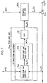
- Fig. 1 A description will be given, with reference to Fig. 1, of a one-channel echo canceller.
- speech uttered by a person at a remote place is provided as a received signal to a received signal terminal 11 and is radiated from a loudspeaker 12.
- k indicates discrete time and x(k) a received signal sample value.
- x(k) will be referred to simply as a received signal.
- An echo canceller 14 cancels an echo y(k) which is produced when the received signal x(k) radiated from the loudspeaker 12 is picked up by a microphone 16 after propagating over an echo path 15.
- received signals x(k) from the current time to L-1 are stored in a received signal storage and vector generating part 17.
- x (k) [x(k), x(k-1), ..., x(k-L+1)] T where * T indicates a transposition.
- an estimated echo generating part 18 formed by an FIR filter the inner product of the received signal vector x (k) of Eq. (2) and an estimated echo path vector (k), which is a filter coefficient vector provided from an echo path estimating part 19, is calculated as follows: As a result, an estimated echo or echo replica ⁇ (k) is generated. This inner product calculation is equivalent to such a convolution as Eq. (1).
- the estimated echo path vector (k) is generated which is used in the estimated echo generating part 18.
- the most common algorithm which is used for the echo path estimation is an NLMS (Normalized Least Mean Square) algorithm.
- NLMS Normalized Least Mean Square
- the residual echo signal e(k) given by Eq. (4) can be reduced.
- a teleconferencing system of the type having an N ( ⁇ 2) channel loudspeaker system and an M ( ⁇ 1) channel microphose system employs, for echo cancellation, such a configuration as shown in Fig. 2. That is to say, an echo cancellation system 23 is composed of N-channel echo cancellers 221, 221, ..., 22 M for processing N-input-one-output time sequence signals, which are each interposed between all of N channels of the receiving side where received signals x l (k) to x N (k) are provided to input terminals ll l to ll N and are radiated from loudspeakers 12 l to 12 N and one channel of the sending side composed of microphones 16 l to 16 M .
- the echo cancellation system has a total of N ⁇ M echo path 15 nm (1 ⁇ n ⁇ N, 1 ⁇ m ⁇ M).
- the N-channel echo cancellers 22 l , 222, ..., 22 M which are each connected between all of the N channels of the receiving side and one channel of the sending side, have such a configuration as shown in Fig 3, which is an extended version of the configuration of the echo canceller 14 depicted in Fig. 1. This is described in detail, for example, in B. Widow and S. D. Stearns, "Adaptive signal processing," Prince-Hall, Inc. pp. 198-200 (1985). Now, consider the N-channel echo canceller 22 m connected to an m-th channel (1 ⁇ m ⁇ M) of the sending side.
- the echo signal y m (k) that is picked up the m-th channel microphone 16 m is obtained by adding together respective received signals of all channels at the sending side after propagation over respective echo paths 15 lm to 15 Nm .
- the following received signal vectors are generated in the received signal storage and vector generating parts (171, 171, ..., 17 N ): where L1, L2, ..., L N are the numbers of taps, which are constants preset corresponding to reverberation times of the respective echo paths 15 1m , 15 1m , ..., 15 Nm .
- x (k) [ x 1 T (k), x 2 T (k), ..., x N T (k)] T
- estimated echo path vectors 1m (k), 2m (k), ..., Nm (k) which are used to simulate N echo paths between the respective receiving side channels and the m-th sending side channel, are combined as follows:
- the updating of the combined estimated echo path vector m (k) is done as follows:
- an estimated echo ⁇ m (k) for the echo y m (k) picked up in the m-th sending channel is generated by the following inner product calculation:
- speaker/microphone systems at points A and B which are connected via a network NW respectively comprise two speakers 12a1, 12a2 and 12b1, 12b2 and two microphones 16a1, 16a2 and 16b1, 16b2.
- the present invention is directed to an N-channel echo cancellation method which comprises the steps of:
- the present invention is directed to an N-channel echo cancellation method which comprises the steps of:
- the present invention is directed to an echo cancellation method for a multi-channel teleconferencing system, which comprises the steps of:
- the echo cancellers according to the present invention have configurations for performing the steps of the first-, second- and third-mentioned methods, respectively.
- the first- or second-mentioned method of the present invention will be described concretely. A description will be given first of the operation of the echo path estimating part of the multi-channel echo canceller in the case where the cross-correlation between multi-channel received signals varies.
- the estimated echo path vector converges to a point ⁇ 11q T (k), 21q T (k) ⁇ of the shortest distance from an initial value ⁇ 11p T (k), 21p T (k) ⁇ .
- This operation is interpreted geometrically as shown in Fig. 5B.
- the steady-state solution ⁇ 11q T , 21q T ⁇ is the intersection of a straight line and its perpendicular line which includes ⁇ h 11p T , h 21p T ⁇ . Accordingly, it is obvious that the norm of filter coefficient error vectors e p and e q generally bear a relationship ⁇ e p ⁇ > ⁇ e q ⁇ .
- the norm of the filter coefficient error vector becomes smaller upon each variation in the cross-correlation between the received signals. That is to say, the variation in the cross-correlation between the multi-channel received signals causes an increase in echo when the echo path estimation is incorrect in the echo canceller, but it can be considered as effective information that permits estimation of the true echo path in the echo path estimating part after the variation in the cross-correlation repeats an infinite number of times. In the past, since such a fact has not been noticed, the cross-correlation between multi-channel received signals has been treated as fixed; therefore, it could have been not supposed that the norm of the error vector becomes small.
- the present invention extracts and utilizes information on the variation in the cross-correlation between received signals of respective channels.
- the multi-channel received signal vectors are combined into a single vector.
- the variation in the cross-correlation between the received signals of the respective channels appears in the auto-correlation which is the correlation between the current combined received signal vector and the past combined received signal vector.
- the projection algorithm has been proposed as a scheme for improving the convergence speed of a speech or similar signal having a high auto-correlation.
- the projection algorithm is described in detail in Ozeki and Umeda, "An Adaptive Filtering Algorithm Using an Orthogonal Projection to an Affine Subspace and Its Properties," Journal of Institute of Electronics, Information and Communication Engineers of Japan (A), J67-App. 126-132, (1984-2).
- v (k) ⁇ 1 x (k)+ ⁇ 2 x (k-1)+...+ ⁇ p x (k-p+1) and the estimated echo path vector (k) is adjusted in the direction of the vector v (k), that is, in the direction in which the correlation to all of p-1 previous combined input signal vectors x (k-1), ..., x (k-p+1) has been removed from the combined vector x (k) of the multi-channel input signals.
- the coefficients ⁇ 1 to ⁇ p are determined so that the vector v (k) becomes a signal having removed similar previous combined input signal vectors from the combined input signal vector.
- Such coefficients ⁇ 1 to ⁇ p can be obtained by calculating the vector g p (k) which satisfies Eq. (27). While ⁇ v (k) is used as the adjustment vector in Eq. (21), v (k) will hereinafter be referred to as an adjustment vector.
- the vector v (k) of Eq. (28) becomes a vector having the variation in the cross-correlation emphasized, with the non-varying component removed.
- the prior art does not recognize that when the cross-correlation between multi-channel received signals varies, the norm of the error vector of the estimated filter coefficients (the estimated echo path vector) becomes small; only an increase in echo is recognized in the prior art.
- the model is simplified and it is assumed that a state change which causes the variation in the cross-correlation, such as the shift or change of the speaker, does not occur. Accordingly, there has not been recognized in the prior art an essential difference between the NLMS algorithm and the projection algorithm as to whether the true transfer function of the echo path can be estimated or not when they are applied to the multi-channel echo canceller; hence, the effectiveness of the projection algorithm in the estimation of the true echo path has not been recognized.
- the coefficients ⁇ 1, ⁇ 2, ..., ⁇ p in Eq. (28) will hereinafter be referred to as pre-filter coefficients, and a vector using them as elements is expressed by the following equation (30) and will be referred to as pre-filter coefficient vector.
- g p (k) [ ⁇ 1 , ⁇ 2 , ..., ⁇ p ] T
- F(k) is the minimum value of the sum of forward a posteriori prediction-error squares.
- b p (k-1) is a p-th order backward linear prediction coefficient vector which satisfies a normal equation R p (k- 1)
- b p (k-1) [0, ..., B(k-1)] T
- its last element is 1.
- B(k-1) is the minimum value of the sum of backward a posteriori prediction-error squares. It is disclosed in J. M. Cioffi and T. Kailath, "Windowed fast transversal adaptive filter algorithms with normalization," IEEE Trans. Acoust., Speech, Signal Processing, vol. ASSP-33, No. 3, pp.
- the adjustment vector v (k) can be calculated with a small amount of calculation.
- the adjustment vector v (k) is derived from the pre-filter coefficient vector g p (k) and is used to adjust the estimated transfer function (the estimated echo path vector) (k) by Eq. (21), it is possible to obtain the estimated echo ⁇ m (k) from the pre-filter coefficient vector g p (k) at high speed and with less computational complexity instead of calculating the adjustment vector v (k), as described below.
- s p-1 (k-1) [s 1 (k-1), s 2 (k-1), ..., s p-1 (k-1)] T
- Fig. 6 illustrates in block form an embodiment of the first method of the present invention applied to the echo canceller 22 m in Fig. 3 which is used in the Fig. 2 teleconferencing system provided with the N-channel loudspeaker system and the M-channel microphone system.
- the parts corresponding to those in Fig. 3 are identified by the same reference numerals.
- a cross-correlation variation extracting part 31 is provided in each of the echo cancellers 221 to 22 M in Fig. 2.
- the received signal x(k) and the residual echo e m (k) in each channel are inputted into the cross-correlation variation extracting part 31, wherein the adjustment vector v (k) is generated.
- the auto-correlation of the combined received signal vector x (k) is removed using the projection algorithm, by which the variation in the cross-correlation between received signals to generate the adjustment vector v (k). That is to say, the cross-correlation variation extracting part 31 stores information about the combined received signal vector x (k) and the residual echo e m (k) defined by Eq. (8), then solves the following equation (52) corresponding to Eq. (27) to obtain g p (k) and generates, by Eq. (28), a decorrelated vector, i.e. the adjustment vector v (k).
- An adjusting part 32 updates the current combined estimated echo path vector m (k) by calculating m (k+1) on the basis of Eqs. (21) and (28) using the adjustment vector v (k) as follows: The combined estimated echo path vector m (k) thus updated is fed to the estimated echo generating part 18 m .
- the variation in the cross-correlation between multi-channel received signal vectors is extracted in the cross-correlation variation extracting part 31 and new multi-channel signal vectors are generated in which the variation in the cross-correlation between the respective received signal vectors are emphasized. Since such a multi-channel signal vector is fed to the adjusting part 32, it is possible to speed up the estimation of the true echo paths.
- Fig. 7 is a block diagram showing a modified form of the cross-correlation variation extracting part, which is formed by a cross-correlation variation coefficient calculating part 31A and a cross-correlation variation emphasized vector generating part 31B and in which the former solves Eq. (27) to obtain the pre-filter coefficient vector g p expressed by Eq. (30) and the latter calculates the adjustment vector v (k) by Eq. (28).
- the cross-correlation variation coefficient calculating part 31A can reduce the amount of calculation of the pre-filter coefficient vector g p (k) through utilization of linear prediction. That is to say, as shown in Fig.
- the cross-correlation variation coefficient calculating part 31A is formed by a linear prediction part 31A1, a pre-filter conductor coefficient vector adjusting part 31A2, a pre-filter coefficient vector adjusting part 31A3 and an error signal vector generating part 31A4.
- the linear prediction part 31A1 calculates the forward linear prediction coefficient vector a p (k) of the combined input signal vector x (k), the minimum value of the sum of forward a posteriori prediction-error squares F(k), the backward linear prediction coefficient vector b p (k) of the combined input signal vector x (k) and the minimum value of the sum of backward a posteriori prediction-error squares B(k).
- the error signal vector generating part 31A4 holds the p latest error signals (residual echoes) e m (k), e m (k-1), ..., e m (k-p+1) iteratively generates the error signal vector e p (k) of Eq. (44) by Eq. (45).
- the pre-filter conductor coefficient vector adjusting part 31A2 calculates the pre-filter conductor coefficient vector f p-1 (k-1) by Eq. (32) and the filter coefficient vector adjusting part 31A3 the pre-filter coefficient vector g p (k) by Eq. (31).
- the pre-filter coefficient vector g p (k) thus obtained is provided to the cross-correlation variation emphasized vector generating part 31B.
- Fig. 9 illustrates a configuration which reduces the amount of calculation in the Fig. 6 embodiment by generating the estimated echo ⁇ m (k), instead of calculating the combined estimated echo path vector m (k), by using the approximate vector z m (k) of the vector m (k) on the basis of the fast projection algorithm described previously in Steps S1 through S11.
- the echo path estimating part 19 m and the estimated echo generating part 18 m in fig. 6 are substituted with the cross-correlation variation coefficient calculating part 31A and the simplified estimated echo generating part 180 m ; the former is identical with that shown in Fig.
- the correlation calculating part 181 calculates the combined input signal vector x (k) and the auto-correlation vector r p-1 (k) of x (k) by Eqs. (40) and (41).
- the smoothing coefficient vector adjusting part 182 calculates by Eq. (50) smoothing coefficient vector s p-1 (k-1) and s p (k) from the pre-filter coefficient vector g p (k).
- the approximated echo path adjusting part 183 calculates by Eq. (51) the approximated echo path vector z m (k) from s p (k) and x (k).
- the inner product calculating part 184 calculates the inner product r p-1 T (k) s p-1 (k-1) of the smoothing coefficient vector s p-1 (k-1) and the correlation vector r p-1 (k).
- the inner product calculating part 185 calculates the inner product z m T (k) x (k) of the input signal vector x (k) and the approximated echo path vector z m (k). These inner products are added together by the adder 186 to obtain the estimated echo signal ⁇ m (k).
- the third method of the present invention will be described concretely.
- a function of actively changing the cross-correlation between received signals of respective channels are adopted, and the received signals added with the variation in the correlation between them are radiated by loudspeakers and used to derive the adjusted vector of the estimated echo.
- the variation in the correlation between received signals of respective channels can be added thereto by (a) filter processing, (b) signal multiplication processing, (c) signal addition processing and (d) pitch shift processing. These methods will hereinafter be described one after another.
- the received signals x1(k), x2(k), ..., x N (k) of respective channels are inputted to time-variant filters with different time-variant characteristics, wherein they are convoluted (indicated by *) with impulse responses q1(k), q2(k), ..., q N (k) of the filters for conversion into signals x ⁇ 1(k), x ⁇ 2(k), ... , x ⁇ N (k) which are expressed as follows:
- the received signals x1(k), x2(k), ..., x N (k) of respective channels are multiplied by different functions u1(k), u2(k), ..., u N (k) for conversion into signals x ⁇ 1(k), x ⁇ 2(k), ... x ⁇ N (k) which are expressed as follows:
- u1(k), u2(k), ..., u N (k) for conversion into signals x ⁇ 1(k), x ⁇ 2(k), ... x ⁇ N (k) which are expressed as follows:
- the received signals x1(k), x2(k), ..., x N (k) of respective channels are added to different functions n1(k), n2(k), n N (k), respectively, for conversion into signals x ⁇ 1(k), x ⁇ 2(k), ..., x ⁇ N (k) which are expressed as follows:
- the frequency characteristics of the received signals x1(k), x2(k), ..., x N (k) of respective channels are each subjected to different time-variant frequency axis expansion or compression, that is, by pitch shift processing, by which the signals are converted into x ⁇ 1(k), x ⁇ 2(k), ..., x ⁇ N (k) signals.
- pitch shift processing by which the signals are converted into x ⁇ 1(k), x ⁇ 2(k), ..., x ⁇ N (k) signals.
- Fig. 11 illustrates an embodiment of the third method of the present invention.
- the parts corresponding to those in Fig. 2 are identified by the same reference numerals.
- a cross-correlation variation adding part 24 is provided at the received signal input side.
- the received signals x1(k), x2(k), ..., x N (k) of the respective channels are converted into x ⁇ 1(k), x ⁇ 2(k), ..., x ⁇ N (k) by being actively added with the variation in their cross-correlation.
- time-variant filters for converting the received signals x1(k), x ⁇ 2(k), ..., x ⁇ N (k) of the respective channels into those x ⁇ 1(k), x2(k), ..., x N (k) which satisfy Eq. (54), through utilization of the impulse response q1(k), q2(k), ..., q N (k) of the filters having different time-variant characteristics. It is said that amplitude information is mainly important for the psycho-acoustic perception and that phase information is not so important. Hence, it is considered that the psycho-acoustic influence of filter processing would be lessened by implementing the time-variant filter so that the amplitude characteristic remain flat with respect to the frequency of each input signal.
- a filer that serves this purpose is an IIR filter which has an all-pass transfer function.
- T and ⁇ respectively.
- G(z) ⁇ z -2 + ⁇ 1 (l+ ⁇ 2 )z -1 + ⁇ 2 ⁇ / ⁇ 1+ ⁇ 1 (1+ ⁇ 2 )z -1 + ⁇ 2 z -2 ⁇
- An advantage of the lattice-type filter configuration in the present invention is that ⁇ 1 and ⁇ 2 can be handled as parameters of independent meanings.
- the group delay characteristic of the transfer function G(z) of Eq. (61) has a peak, the peak frequency depends virtually only on ⁇ 1 and the steepness of the peak depends virtually only on ⁇ 2.
- the values of the gain coefficients A1, A2, ..., A N be equal or take values of the same sign; in this instance, the functions u1(k), u2(k), ..., u N (k) all take values of the same sign. Furthermore, the amount of distortion of each processed signal can be adjusted by the scalar values k1, k2, ..., k N .
- n1(k), n2(k), ..., n N (k) be moderately smaller in amplitude value than the received signals x1(k), x2(k), ..., x N (k) of the respective channels.
- n r1 (k), n r2 (k), ..., n rN (k) are multiplied by scalar values ⁇ 1, ⁇ 2, ..., ⁇ N , by which the functions n1(k), n2(k), ..., n N (k) are expressed as follows: Based on the scalar values ⁇ 1, ⁇ 2, ..., ⁇ N , it is possible to determine the degree to which the magnitude of the signal to be added to each of the received signals x1(k), x2(k), ..., x N (k) is made smaller than the rated value A r .
- the pitch shift processing involves time expansion/compression as well as frequency axis expansion/compression and can be processed in the time domain.
- interpolation processing is needed to make the duration of the processed signal equal to the duration of the original signal, whereas when the time axis is expanded, the duration of the processed signal becomes longer than the duration of the original signal; hence decimation processing is needed.
- Such interpolation/decimation processing can be implemented by detecting a silent duration and extending or removing it.
- the methods of the present invention can be applied to the cancellation of echoes to implement a teleconference system of highly realistic presence which permits transmission of acoustic spatial information from either point by using a multi-channel transmission system and terminal equipment provided with multi-channel microphone and loudspeaker systems between two point.
- a stereo teleconferencing system which connects two points via a two-channel transmission system and uses two-channel microphone and loudspeaker systems as shown in Fig. 4.
- the stereo speech signals that are picked up by two microphones bear a cross-correlation therebetween dependent on the positional relationship between the speakers and the microphones.
- the echo path estimation depends on the cross-correlation and hence is incorrect, with the result that a large echo returns to the point A each time the speaker changes.
- the echo cancellation method of the present invention when the echo cancellation method of the present invention, a variation in the cross-correlation between the stereo received signals by the change of the speaker is extracted and used to correct an error in the echo path estimation; thus, it is possible to suppress the echo from increasing whenever the speaker changes. Furthermore, in the case where speech uttered by one person is picked up by a plurality of microphones, even if the speaker speaks at one place, the cross-correlation between the speech signals picked up by the microphone delicately changes. The method of the present invention permits effective utilization of such a slight variation in the cross-correlation between signals.
- Fig. 13 is a graph showing the results of computer simulations using stereophonically picked up speech uttered by a speaker with his body or head fixed; the prior art method and this invention method are compared in terms of the error vector between the combined estimated echo path vector generated in the echo path estimating part and the combined true echo path vector as indicated by the curves 13A and 13B.
- This invention method used the secondary projection algorithm for the extraction of the variation in the cross-correlation. From Fig. 13 it will be seen that this invention method captures even a delicate variation in the cross-correlation between signals, permitting the correction of an error in the echo path estimation. It can be said that the present invention effectively detects a delicate variation between channels through utilization of past data.
- Fig. 14 is a graph showing the convergence of the estimated echo path vector in the case of stereophonically picked up speech as in the case of Fig. 13, the order p of the projection algorithm being used as a parameter.
- the number L of taps was set to 500+500 and the step size ⁇ was set to 0.5. This graph also indicates that the present invention is effective.
- Fig. 15 illustrates the configuration of teleconferencing system for four points interconnected via a network. At each point, the sending or microphone system is one-channel (monaural). Now, the point D will be described.
- the curves 16A and 16B in Fig. 16 show the convergence of the error vector in the case of using, as received signals, two-channel signals obtained by picking up speech uttered by one speaker with one microphone and applying the speech through two different time-invariant filters on a computer, that is, in the case where the cross-correlation between the received signal is constant.
- the first or second method of the present invention is employed to extract a variation in the cross-correlation between the received signals, since the cross-correlation between the received signals does not vary, echo path estimation is made incorrectly, and hence the effect of echo cancellation is not heightened even compared with that by the conventional method.
- the cross-correlation between the received signals always varies and the echo path estimation is made at all times.
- the configuration therefor is the same as shown in Fig, 11, and the N-channel echo cancellers 221, 222, ..., 22 M are identical in construction with that shown in Fig. 6.
- the curves 17A and 17B in Fig. 17 indicates the results of computer simulations done on the method of extracting and using the variation in the cross-correlation between received signals in the cases where the same received signals as those used in the case of Fig.
- the conventional echo cancellation method is applied to a teleconferencing system usually composed of a multi-channel loudspeaker system and one or more microphone channels
- when received signals of respective channels have a cross-correlation therebetween incorrect echo path estimation is made, with the result that the echo increases upon each variation in the cross-correlation between the received signals.
- the first or second method of the present invention extracts and utilizes the variation in the cross-correlation between received signals to correct an error in the echo path estimation, and hence is effective in settling the above-said problem.
- the third method of the present invention has the function of adding a variation to the cross-correlation between received signals, and hence does not completely freeze at a wrong solution in the echo path estimation but continues the echo path estimation in the direction in which to reduce the error; thus, the third method also effective in solving the problem.
- the first or second method effectively works when the cross-correlation between received signal varies, and when the cross-correlation does not vary, the third method effectively works to make the correction of the estimated echo path to converge in a short time.
Landscapes
- Engineering & Computer Science (AREA)
- Signal Processing (AREA)
- Cable Transmission Systems, Equalization Of Radio And Reduction Of Echo (AREA)
- Filters That Use Time-Delay Elements (AREA)
Applications Claiming Priority (6)
| Application Number | Priority Date | Filing Date | Title |
|---|---|---|---|
| JP26273894 | 1994-10-26 | ||
| JP262738/94 | 1994-10-26 | ||
| JP26273894 | 1994-10-26 | ||
| JP5000295 | 1995-03-09 | ||
| JP50002/95 | 1995-03-09 | ||
| JP05000295A JP3397269B2 (ja) | 1994-10-26 | 1995-03-09 | 多チャネル反響消去方法 |
Publications (3)
| Publication Number | Publication Date |
|---|---|
| EP0709999A2 true EP0709999A2 (de) | 1996-05-01 |
| EP0709999A3 EP0709999A3 (de) | 1997-05-14 |
| EP0709999B1 EP0709999B1 (de) | 2003-06-25 |
Family
ID=26390434
Family Applications (1)
| Application Number | Title | Priority Date | Filing Date |
|---|---|---|---|
| EP95116767A Expired - Lifetime EP0709999B1 (de) | 1994-10-26 | 1995-10-24 | Verfahren und Einrichtung zur mehrkanaligen Kompensation eines akustischen Echos |
Country Status (5)
| Country | Link |
|---|---|
| US (1) | US5661813A (de) |
| EP (1) | EP0709999B1 (de) |
| JP (1) | JP3397269B2 (de) |
| CA (1) | CA2161358C (de) |
| DE (1) | DE69531136T2 (de) |
Cited By (5)
| Publication number | Priority date | Publication date | Assignee | Title |
|---|---|---|---|---|
| WO1998047276A1 (fr) * | 1997-04-16 | 1998-10-22 | France Telecom | Procede d'annulation d'echo acoustique multi-voies et annuleur d'echo acoustique multi-voies |
| WO1998053595A1 (fr) * | 1997-05-21 | 1998-11-26 | France Telecom | Procede et dispositif de reduction d'echo acoustique multivoies et de spatialisation sonore |
| EP0944228A1 (de) * | 1998-03-05 | 1999-09-22 | Nippon Telegraph and Telephone Corporation | Verfahren und Einrichtung zur mehrkanaligen Kompensation eines akustischen Echos |
| WO2001045375A1 (fr) * | 1999-12-14 | 2001-06-21 | France Telecom | Procede temps reel de traitemten et de gestion pour l'annulation d'echo entre haut-parleur et microphone d'un terminal informatique |
| WO2003007500A1 (fr) | 2001-07-11 | 2003-01-23 | Yamaha Corporation | Procede de suppression d'echo multivoies, procede de transfert de son multivoies, dispositif de suppression d'echo stereo, appareil de transfert d'echo stereo, et appareil de calcul de fonction de transfert |
Families Citing this family (65)
| Publication number | Priority date | Publication date | Assignee | Title |
|---|---|---|---|---|
| US5761318A (en) * | 1995-09-26 | 1998-06-02 | Nippon Telegraph And Telephone Corporation | Method and apparatus for multi-channel acoustic echo cancellation |
| US5923749A (en) * | 1995-12-06 | 1999-07-13 | Telefonaktiebolaget Lm Ericsson | Method and system for eliminating acoustic echos in a digital telecommunication system |
| JP3654470B2 (ja) * | 1996-09-13 | 2005-06-02 | 日本電信電話株式会社 | サブバンド多チャネル音声通信会議用反響消去方法 |
| US5764512A (en) * | 1996-10-04 | 1998-06-09 | Lucent Technologies Inc. | Intelligent acoustic systems peripheral |
| SE512903C2 (sv) * | 1997-10-29 | 2000-06-05 | Telia Ab | Metod och anordning vid stereoakustisk ekosläckning |
| US6895093B1 (en) * | 1998-03-03 | 2005-05-17 | Texas Instruments Incorporated | Acoustic echo-cancellation system |
| US6785391B1 (en) * | 1998-05-22 | 2004-08-31 | Nippon Telegraph And Telephone Corporation | Apparatus and method for simultaneous estimation of transfer characteristics of multiple linear transmission paths |
| JP3781902B2 (ja) * | 1998-07-01 | 2006-06-07 | 株式会社リコー | 音像定位制御装置および音像定位制御方式 |
| EP1180300B1 (de) * | 1999-05-25 | 2006-07-19 | BRITISH TELECOMMUNICATIONS public limited company | Akusticher echokompensator |
| US6694020B1 (en) * | 1999-09-14 | 2004-02-17 | Agere Systems, Inc. | Frequency domain stereophonic acoustic echo canceller utilizing non-linear transformations |
| DE19960242C1 (de) * | 1999-12-14 | 2001-06-21 | Infineon Technologies Ag | Verfahren und Anordnung zur Kompensation von Signalechos bei der Duplex-Datenübertragung bei der diskreten Multitonmodulation |
| JP4734714B2 (ja) * | 2000-12-22 | 2011-07-27 | ヤマハ株式会社 | 収音再生方法およびその装置 |
| WO2005020120A2 (en) * | 2003-08-20 | 2005-03-03 | Koninklijke Philips Electronics N.V. | A system and method for detecting signal artifacts |
| JP4630956B2 (ja) * | 2004-03-30 | 2011-02-09 | 学校法人早稲田大学 | ハウリング周波数成分強調方法およびその装置、ハウリング検出方法およびその装置、ハウリング抑圧方法およびその装置、ピーク周波数成分強調方法およびその装置 |
| US7352858B2 (en) * | 2004-06-30 | 2008-04-01 | Microsoft Corporation | Multi-channel echo cancellation with round robin regularization |
| US8457614B2 (en) * | 2005-04-07 | 2013-06-04 | Clearone Communications, Inc. | Wireless multi-unit conference phone |
| US8594320B2 (en) * | 2005-04-19 | 2013-11-26 | (Epfl) Ecole Polytechnique Federale De Lausanne | Hybrid echo and noise suppression method and device in a multi-channel audio signal |
| US7876906B2 (en) | 2006-05-30 | 2011-01-25 | Sonitus Medical, Inc. | Methods and apparatus for processing audio signals |
| US8291912B2 (en) | 2006-08-22 | 2012-10-23 | Sonitus Medical, Inc. | Systems for manufacturing oral-based hearing aid appliances |
| US8270638B2 (en) | 2007-05-29 | 2012-09-18 | Sonitus Medical, Inc. | Systems and methods to provide communication, positioning and monitoring of user status |
| US8433080B2 (en) | 2007-08-22 | 2013-04-30 | Sonitus Medical, Inc. | Bone conduction hearing device with open-ear microphone |
| US8224013B2 (en) | 2007-08-27 | 2012-07-17 | Sonitus Medical, Inc. | Headset systems and methods |
| US7682303B2 (en) | 2007-10-02 | 2010-03-23 | Sonitus Medical, Inc. | Methods and apparatus for transmitting vibrations |
| US8050398B1 (en) | 2007-10-31 | 2011-11-01 | Clearone Communications, Inc. | Adaptive conferencing pod sidetone compensator connecting to a telephonic device having intermittent sidetone |
| US8199927B1 (en) | 2007-10-31 | 2012-06-12 | ClearOnce Communications, Inc. | Conferencing system implementing echo cancellation and push-to-talk microphone detection using two-stage frequency filter |
| US8795172B2 (en) | 2007-12-07 | 2014-08-05 | Sonitus Medical, Inc. | Systems and methods to provide two-way communications |
| US7974845B2 (en) | 2008-02-15 | 2011-07-05 | Sonitus Medical, Inc. | Stuttering treatment methods and apparatus |
| US8270637B2 (en) | 2008-02-15 | 2012-09-18 | Sonitus Medical, Inc. | Headset systems and methods |
| US8023676B2 (en) * | 2008-03-03 | 2011-09-20 | Sonitus Medical, Inc. | Systems and methods to provide communication and monitoring of user status |
| US20090226020A1 (en) | 2008-03-04 | 2009-09-10 | Sonitus Medical, Inc. | Dental bone conduction hearing appliance |
| US8150075B2 (en) | 2008-03-04 | 2012-04-03 | Sonitus Medical, Inc. | Dental bone conduction hearing appliance |
| WO2010035658A1 (ja) * | 2008-09-26 | 2010-04-01 | 日本電気株式会社 | 信号処理方法、信号処理装置、および信号処理プログラム |
| US8433082B2 (en) | 2009-10-02 | 2013-04-30 | Sonitus Medical, Inc. | Intraoral appliance for sound transmission via bone conduction |
| JP5604275B2 (ja) * | 2010-12-02 | 2014-10-08 | 富士通テン株式会社 | 相関低減方法、音声信号変換装置および音響再生装置 |
| US9712866B2 (en) | 2015-04-16 | 2017-07-18 | Comigo Ltd. | Cancelling TV audio disturbance by set-top boxes in conferences |
| US9565493B2 (en) | 2015-04-30 | 2017-02-07 | Shure Acquisition Holdings, Inc. | Array microphone system and method of assembling the same |
| US9554207B2 (en) | 2015-04-30 | 2017-01-24 | Shure Acquisition Holdings, Inc. | Offset cartridge microphones |
| CN105280195B (zh) * | 2015-11-04 | 2018-12-28 | 腾讯科技(深圳)有限公司 | 语音信号的处理方法及装置 |
| US9653060B1 (en) * | 2016-02-09 | 2017-05-16 | Amazon Technologies, Inc. | Hybrid reference signal for acoustic echo cancellation |
| US9659555B1 (en) * | 2016-02-09 | 2017-05-23 | Amazon Technologies, Inc. | Multichannel acoustic echo cancellation |
| US10367948B2 (en) | 2017-01-13 | 2019-07-30 | Shure Acquisition Holdings, Inc. | Post-mixing acoustic echo cancellation systems and methods |
| CN107749304B (zh) * | 2017-09-07 | 2021-04-06 | 电信科学技术研究院 | 有限冲激响应滤波器系数矢量的可持续更新方法及装置 |
| US10522167B1 (en) * | 2018-02-13 | 2019-12-31 | Amazon Techonlogies, Inc. | Multichannel noise cancellation using deep neural network masking |
| US11523212B2 (en) | 2018-06-01 | 2022-12-06 | Shure Acquisition Holdings, Inc. | Pattern-forming microphone array |
| US11297423B2 (en) | 2018-06-15 | 2022-04-05 | Shure Acquisition Holdings, Inc. | Endfire linear array microphone |
| US11310596B2 (en) | 2018-09-20 | 2022-04-19 | Shure Acquisition Holdings, Inc. | Adjustable lobe shape for array microphones |
| US11558693B2 (en) | 2019-03-21 | 2023-01-17 | Shure Acquisition Holdings, Inc. | Auto focus, auto focus within regions, and auto placement of beamformed microphone lobes with inhibition and voice activity detection functionality |
| CN118803494B (zh) | 2019-03-21 | 2025-09-19 | 舒尔获得控股公司 | 具有抑制功能的波束形成麦克风瓣的自动对焦、区域内自动对焦、及自动配置 |
| CN113841419B (zh) | 2019-03-21 | 2024-11-12 | 舒尔获得控股公司 | 天花板阵列麦克风的外壳及相关联设计特征 |
| CN114051738B (zh) | 2019-05-23 | 2024-10-01 | 舒尔获得控股公司 | 可操纵扬声器阵列、系统及其方法 |
| CN114051637B (zh) | 2019-05-31 | 2025-10-28 | 舒尔获得控股公司 | 集成语音及噪声活动检测的低延时自动混波器 |
| CN114467312A (zh) | 2019-08-23 | 2022-05-10 | 舒尔获得控股公司 | 具有改进方向性的二维麦克风阵列 |
| US12028678B2 (en) | 2019-11-01 | 2024-07-02 | Shure Acquisition Holdings, Inc. | Proximity microphone |
| US11552611B2 (en) | 2020-02-07 | 2023-01-10 | Shure Acquisition Holdings, Inc. | System and method for automatic adjustment of reference gain |
| USD944776S1 (en) | 2020-05-05 | 2022-03-01 | Shure Acquisition Holdings, Inc. | Audio device |
| WO2021243368A2 (en) | 2020-05-29 | 2021-12-02 | Shure Acquisition Holdings, Inc. | Transducer steering and configuration systems and methods using a local positioning system |
| CN112087178A (zh) * | 2020-09-14 | 2020-12-15 | 四川长虹电器股份有限公司 | 一种永磁同步电机的参数识别方法 |
| CN116918351A (zh) | 2021-01-28 | 2023-10-20 | 舒尔获得控股公司 | 混合音频波束成形系统 |
| US12452584B2 (en) | 2021-01-29 | 2025-10-21 | Shure Acquisition Holdings, Inc. | Scalable conferencing systems and methods |
| CN113192527B (zh) * | 2021-04-28 | 2024-03-19 | 北京达佳互联信息技术有限公司 | 用于消除回声的方法、装置、电子设备和存储介质 |
| US12542123B2 (en) | 2021-08-31 | 2026-02-03 | Shure Acquisition Holdings, Inc. | Mask non-linear processor for acoustic echo cancellation |
| WO2023059655A1 (en) | 2021-10-04 | 2023-04-13 | Shure Acquisition Holdings, Inc. | Networked automixer systems and methods |
| EP4427465A1 (de) | 2021-11-05 | 2024-09-11 | Shure Acquisition Holdings, Inc. | Verteilter algorithmus zur automatischen mischung von sprache über drahtlose netzwerke |
| WO2023133513A1 (en) | 2022-01-07 | 2023-07-13 | Shure Acquisition Holdings, Inc. | Audio beamforming with nulling control system and methods |
| CN115857052B (zh) * | 2023-02-22 | 2023-05-09 | 中国民用航空飞行学院 | 具有降噪功能的航行气象信息接收设备及播报装置 |
Family Cites Families (8)
| Publication number | Priority date | Publication date | Assignee | Title |
|---|---|---|---|---|
| US3794766A (en) * | 1973-02-08 | 1974-02-26 | Bell Telephone Labor Inc | Delay equalizing circuit for an audio system using multiple microphones |
| US4131760A (en) * | 1977-12-07 | 1978-12-26 | Bell Telephone Laboratories, Incorporated | Multiple microphone dereverberation system |
| CA2004379C (en) * | 1988-12-01 | 1993-07-06 | Tetsu Taguchi | Echo canceller with means for determining filter coefficients from autocorrelation and cross-correlation coefficients |
| JP2792311B2 (ja) * | 1992-01-31 | 1998-09-03 | 日本電気株式会社 | 多チャンネルエコー除去方法および装置 |
| JP2508574B2 (ja) * | 1992-11-10 | 1996-06-19 | 日本電気株式会社 | 多チャンネルエコ―除去装置 |
| JPH084243B2 (ja) * | 1993-05-31 | 1996-01-17 | 日本電気株式会社 | 多チャンネルエコー除去方法および装置 |
| US5327496A (en) * | 1993-06-30 | 1994-07-05 | Iowa State University Research Foundation, Inc. | Communication device, apparatus, and method utilizing pseudonoise signal for acoustical echo cancellation |
| US5473686A (en) * | 1994-02-01 | 1995-12-05 | Tandy Corporation | Echo cancellation apparatus |
-
1995
- 1995-03-09 JP JP05000295A patent/JP3397269B2/ja not_active Expired - Lifetime
- 1995-10-24 DE DE69531136T patent/DE69531136T2/de not_active Expired - Lifetime
- 1995-10-24 US US08/547,545 patent/US5661813A/en not_active Expired - Lifetime
- 1995-10-24 EP EP95116767A patent/EP0709999B1/de not_active Expired - Lifetime
- 1995-10-25 CA CA002161358A patent/CA2161358C/en not_active Expired - Lifetime
Cited By (13)
| Publication number | Priority date | Publication date | Assignee | Title |
|---|---|---|---|---|
| WO1998047276A1 (fr) * | 1997-04-16 | 1998-10-22 | France Telecom | Procede d'annulation d'echo acoustique multi-voies et annuleur d'echo acoustique multi-voies |
| FR2762467A1 (fr) * | 1997-04-16 | 1998-10-23 | France Telecom | Procede d'annulation d'echo acoustique multi-voies et annuleur d'echo acoustique multi-voies |
| US6556682B1 (en) | 1997-04-16 | 2003-04-29 | France Telecom | Method for cancelling multi-channel acoustic echo and multi-channel acoustic echo canceller |
| FR2763774A1 (fr) * | 1997-05-21 | 1998-11-27 | France Telecom | Procede et dispositif de reduction d'echo acoustique multivoies et de spatialisation sonore |
| US6424720B1 (en) | 1997-05-21 | 2002-07-23 | France Telecom | Method and device for reducing multi-channel acoustic echo and adapting sound to space conditions |
| WO1998053595A1 (fr) * | 1997-05-21 | 1998-11-26 | France Telecom | Procede et dispositif de reduction d'echo acoustique multivoies et de spatialisation sonore |
| EP0944228A1 (de) * | 1998-03-05 | 1999-09-22 | Nippon Telegraph and Telephone Corporation | Verfahren und Einrichtung zur mehrkanaligen Kompensation eines akustischen Echos |
| US6553122B1 (en) | 1998-03-05 | 2003-04-22 | Nippon Telegraph And Telephone Corporation | Method and apparatus for multi-channel acoustic echo cancellation and recording medium with the method recorded thereon |
| WO2001045375A1 (fr) * | 1999-12-14 | 2001-06-21 | France Telecom | Procede temps reel de traitemten et de gestion pour l'annulation d'echo entre haut-parleur et microphone d'un terminal informatique |
| US7555116B1 (en) | 1999-12-14 | 2009-06-30 | France Telecom | Real time processing and management method for cancelling out the echo between a loudspeaker and a microphone of a computer terminal |
| WO2003007500A1 (fr) | 2001-07-11 | 2003-01-23 | Yamaha Corporation | Procede de suppression d'echo multivoies, procede de transfert de son multivoies, dispositif de suppression d'echo stereo, appareil de transfert d'echo stereo, et appareil de calcul de fonction de transfert |
| US7925006B2 (en) | 2001-07-11 | 2011-04-12 | Yamaha Corporation | Multi-channel echo cancel method, multi-channel sound transfer method, stereo echo canceller, stereo sound transfer apparatus and transfer function calculation apparatus |
| US7925008B2 (en) | 2001-07-11 | 2011-04-12 | Yamaha Corporation | Multi-channel echo cancel method, multi-channel sound transfer method, stereo echo canceller, stereo sound transfer apparatus and transfer function calculation apparatus |
Also Published As
| Publication number | Publication date |
|---|---|
| DE69531136D1 (de) | 2003-07-31 |
| EP0709999B1 (de) | 2003-06-25 |
| CA2161358C (en) | 1999-09-28 |
| CA2161358A1 (en) | 1996-04-27 |
| JPH08181639A (ja) | 1996-07-12 |
| US5661813A (en) | 1997-08-26 |
| EP0709999A3 (de) | 1997-05-14 |
| DE69531136T2 (de) | 2004-05-06 |
| JP3397269B2 (ja) | 2003-04-14 |
Similar Documents
| Publication | Publication Date | Title |
|---|---|---|
| EP0709999B1 (de) | Verfahren und Einrichtung zur mehrkanaligen Kompensation eines akustischen Echos | |
| US6246760B1 (en) | Subband echo cancellation method for multichannel audio teleconference and echo canceller using the same | |
| EP1855457B1 (de) | Kompensation von Mehrkanalechos durch Dekorrelation | |
| EP0766446B1 (de) | Verfahren und Einrichtung zur mehrkanaligen Kompensation eines akustischen Echos | |
| US5208786A (en) | Multi-channel signal separation | |
| US5774562A (en) | Method and apparatus for dereverberation | |
| EP1848243B1 (de) | System und Verfahren zur Mehrkanal-Echokompensation | |
| CN100477704C (zh) | 用于与自适应波束形成组合的回声抵消的方法和设备 | |
| US5272695A (en) | Subband echo canceller with adjustable coefficients using a series of step sizes | |
| EP0944228B1 (de) | Verfahren und Einrichtung zur mehrkanaligen Kompensation eines akustischen Echos | |
| US9203972B2 (en) | Efficient audio signal processing in the sub-band regime | |
| US6700977B2 (en) | Method and apparatus for cancelling multi-channel echo | |
| JP3099870B2 (ja) | 音響エコーキャンセラ | |
| EP0809893A1 (de) | Echokompensator mit kalman-filter zur optimalen adaption | |
| US6381272B1 (en) | Multi-channel adaptive filtering | |
| Gilloire et al. | State of the art in acoustic echo cancellation | |
| Makino et al. | Subband stereo echo canceller using the projection algorithm with fast convergence to the true echo path | |
| US6694020B1 (en) | Frequency domain stereophonic acoustic echo canceller utilizing non-linear transformations | |
| JP3402427B2 (ja) | 多チャネル反響消去方法及び装置 | |
| US6968352B1 (en) | Device for digital processing with frequency filtering and reduced computation complexity | |
| JP4041770B2 (ja) | 音響エコー消去方法、その装置、プログラム及びその記録媒体 | |
| JP2007511966A (ja) | 通信システムにおけるエコーを低減するための方法および装置 | |
| JP3616341B2 (ja) | 多チャネルエコーキャンセル方法、その装置、そのプログラム及び記録媒体 | |
| JP2002223182A (ja) | 反響消去方法、その装置、そのプログラム及びその記録媒体 | |
| JP3131202B2 (ja) | 多重線形伝達経路の伝達特性の分離推定装置、分離推定方法及びその方法を読みとり可能なプログラムとして記録した記録媒体 |
Legal Events
| Date | Code | Title | Description |
|---|---|---|---|
| PUAI | Public reference made under article 153(3) epc to a published international application that has entered the european phase |
Free format text: ORIGINAL CODE: 0009012 |
|
| 17P | Request for examination filed |
Effective date: 19951025 |
|
| AK | Designated contracting states |
Kind code of ref document: A2 Designated state(s): DE FR GB |
|
| PUAL | Search report despatched |
Free format text: ORIGINAL CODE: 0009013 |
|
| AK | Designated contracting states |
Kind code of ref document: A3 Designated state(s): DE FR GB |
|
| GRAH | Despatch of communication of intention to grant a patent |
Free format text: ORIGINAL CODE: EPIDOS IGRA |
|
| GRAH | Despatch of communication of intention to grant a patent |
Free format text: ORIGINAL CODE: EPIDOS IGRA |
|
| GRAA | (expected) grant |
Free format text: ORIGINAL CODE: 0009210 |
|
| AK | Designated contracting states |
Designated state(s): DE FR GB |
|
| REG | Reference to a national code |
Ref country code: GB Ref legal event code: FG4D |
|
| REF | Corresponds to: |
Ref document number: 69531136 Country of ref document: DE Date of ref document: 20030731 Kind code of ref document: P |
|
| PLBE | No opposition filed within time limit |
Free format text: ORIGINAL CODE: 0009261 |
|
| STAA | Information on the status of an ep patent application or granted ep patent |
Free format text: STATUS: NO OPPOSITION FILED WITHIN TIME LIMIT |
|
| ET | Fr: translation filed | ||
| 26N | No opposition filed |
Effective date: 20040326 |
|
| PGFP | Annual fee paid to national office [announced via postgrant information from national office to epo] |
Ref country code: FR Payment date: 20140730 Year of fee payment: 20 |
|
| PGFP | Annual fee paid to national office [announced via postgrant information from national office to epo] |
Ref country code: GB Payment date: 20141022 Year of fee payment: 20 Ref country code: DE Payment date: 20141031 Year of fee payment: 20 |
|
| REG | Reference to a national code |
Ref country code: DE Ref legal event code: R071 Ref document number: 69531136 Country of ref document: DE |
|
| REG | Reference to a national code |
Ref country code: GB Ref legal event code: PE20 Expiry date: 20151023 |
|
| PG25 | Lapsed in a contracting state [announced via postgrant information from national office to epo] |
Ref country code: GB Free format text: LAPSE BECAUSE OF EXPIRATION OF PROTECTION Effective date: 20151023 |