EP0709591B1 - Ausrückeranordnung für eine Kraftfahrzeug-Reibungskupplung - Google Patents
Ausrückeranordnung für eine Kraftfahrzeug-Reibungskupplung Download PDFInfo
- Publication number
- EP0709591B1 EP0709591B1 EP95117531A EP95117531A EP0709591B1 EP 0709591 B1 EP0709591 B1 EP 0709591B1 EP 95117531 A EP95117531 A EP 95117531A EP 95117531 A EP95117531 A EP 95117531A EP 0709591 B1 EP0709591 B1 EP 0709591B1
- Authority
- EP
- European Patent Office
- Prior art keywords
- ring
- spring
- releasing
- arrangement according
- axially
- Prior art date
- Legal status (The legal status is an assumption and is not a legal conclusion. Google has not performed a legal analysis and makes no representation as to the accuracy of the status listed.)
- Expired - Lifetime
Links
- 230000005540 biological transmission Effects 0.000 claims description 69
- 210000002105 tongue Anatomy 0.000 claims description 53
- 238000002485 combustion reaction Methods 0.000 claims description 9
- 239000002184 metal Substances 0.000 claims description 6
- 230000002093 peripheral effect Effects 0.000 claims description 6
- 238000006073 displacement reaction Methods 0.000 claims description 4
- 230000007423 decrease Effects 0.000 claims description 3
- 230000036316 preload Effects 0.000 description 20
- 238000007789 sealing Methods 0.000 description 5
- 230000008878 coupling Effects 0.000 description 4
- 238000010168 coupling process Methods 0.000 description 4
- 238000005859 coupling reaction Methods 0.000 description 4
- 238000000034 method Methods 0.000 description 4
- 230000008569 process Effects 0.000 description 4
- 230000004308 accommodation Effects 0.000 description 3
- 210000000078 claw Anatomy 0.000 description 3
- 238000009434 installation Methods 0.000 description 3
- 238000010276 construction Methods 0.000 description 2
- 230000000694 effects Effects 0.000 description 2
- 239000012528 membrane Substances 0.000 description 2
- 230000009471 action Effects 0.000 description 1
- 230000000712 assembly Effects 0.000 description 1
- 238000000429 assembly Methods 0.000 description 1
- 230000004323 axial length Effects 0.000 description 1
- 238000005452 bending Methods 0.000 description 1
- 230000008901 benefit Effects 0.000 description 1
- 230000015572 biosynthetic process Effects 0.000 description 1
- 238000010586 diagram Methods 0.000 description 1
- 230000005489 elastic deformation Effects 0.000 description 1
- 230000006872 improvement Effects 0.000 description 1
- 239000000463 material Substances 0.000 description 1
- 230000009467 reduction Effects 0.000 description 1
- 230000000284 resting effect Effects 0.000 description 1
- 230000000630 rising effect Effects 0.000 description 1
Images

Classifications
-
- F—MECHANICAL ENGINEERING; LIGHTING; HEATING; WEAPONS; BLASTING
- F16—ENGINEERING ELEMENTS AND UNITS; GENERAL MEASURES FOR PRODUCING AND MAINTAINING EFFECTIVE FUNCTIONING OF MACHINES OR INSTALLATIONS; THERMAL INSULATION IN GENERAL
- F16D—COUPLINGS FOR TRANSMITTING ROTATION; CLUTCHES; BRAKES
- F16D23/00—Details of mechanically-actuated clutches not specific for one distinct type
- F16D23/12—Mechanical clutch-actuating mechanisms arranged outside the clutch as such
- F16D23/14—Clutch-actuating sleeves or bearings; Actuating members directly connected to clutch-actuating sleeves or bearings
- F16D23/143—Arrangements or details for the connection between the release bearing and the diaphragm
- F16D23/144—With a disengaging thrust-ring distinct from the release bearing, and secured to the diaphragm
- F16D23/146—Arrangements for the connection between the thrust-ring and the release bearing
-
- F—MECHANICAL ENGINEERING; LIGHTING; HEATING; WEAPONS; BLASTING
- F16—ENGINEERING ELEMENTS AND UNITS; GENERAL MEASURES FOR PRODUCING AND MAINTAINING EFFECTIVE FUNCTIONING OF MACHINES OR INSTALLATIONS; THERMAL INSULATION IN GENERAL
- F16D—COUPLINGS FOR TRANSMITTING ROTATION; CLUTCHES; BRAKES
- F16D13/00—Friction clutches
- F16D13/58—Details
- F16D13/70—Pressure members, e.g. pressure plates, for clutch-plates or lamellae; Guiding arrangements for pressure members
- F16D2013/706—Pressure members, e.g. pressure plates, for clutch-plates or lamellae; Guiding arrangements for pressure members the axially movable pressure plate is supported by leaf springs
Definitions
- the invention relates to a release arrangement for a Powertrain between an internal combustion engine and one Gearbox of a motor vehicle arranged friction clutch.
- the release arrangement includes a concentric to the axis of rotation release ring attached to the spring tongues, which itself supported on the motor side of the spring tongues and one in the direction the axis of rotation movable, for example on the transmission slidable release bearing with a rotating one inner bearing ring and a non-rotating outer Bearing ring.
- To the release bearing which is usually difficult to access in a coupling enclosing the coupling Bell of the gearbox is easier to assemble are snap connection means that can be axially coupled to one another provided between the release ring and the rotating bearing ring.
- the snap connection means are approximated by conical power transmission ring surfaces on the release ring and formed and comprise the rotating bearing ring a radially resilient load transmission ring, which between the power transmission ring surfaces can be snapped.
- the snap connection means by preload forces within the clutch actuation system are preloaded in the disengaging direction, to ensure that the components of the snap connection always remain in mutual investment.
- this motor vehicle it is not always possible for this motor vehicle to have this preload to keep up permanently and at the same time for if possible to ensure low preload forces.
- Preload forces too high at this point the life of the release bearing reduce and at the same time the function of the friction clutch affect because the biasing force of the force of Counteract the main clutch spring. For example, under certain circumstances by vibrations of the internal combustion engine the contact of the individual parts of the snap connection at short notice are lost, so that increased wear at these points occurs.
- a release arrangement is known from FR 2 622 265 A, at which on the diaphragm spring tongues the main clutch spring forming a diaphragm is attached to a support ring which is riveted to an axially resilient washer.
- the washer is in a circumferential groove on the rotating bearing ring of the Release bearing snap-in or fixed to the carrier ring an additional power transmission ring, which in turn snap into the circumferential groove of the rotating bearing ring is.
- the improvement according to the invention is characterized in that that the spring element is arranged with a bias, the value of the snap connection means that are not coupled to one another is dimensioned so that both this value of the preload as well as the value of the bias of the spring element in the case of coupled fasteners a branch of the spring force-spring characteristic of the spring element lie in which the spring force with increasing spring travel decreases.
- the biasing element thus ensures in a manner known per se regardless of possibly via the clutch actuation system exercised forces for a permanent investment contact between the power transmission surfaces that are over the load transmission element support each other.
- the biasing element can be specially adapted to this task, so that even in the short term Loss of system contact is avoided. Because the biasing element in the area of the rotating bearing ring and the Disengagement ring or the disengagement elements is arranged is only little additional space is required.
- the preload element frees the clutch control system including the Release bearing before a possible overload due to the previously required for the pretensioning of the snap connection means Forces in the actuation system.
- the spring element designed as a plate or diaphragm spring is in a preferred embodiment on the engine side of the Release ring arranged in the area of its outer circumference held the release ring and in the area of its inner circumference supported on the rotating bearing ring.
- the space requirement of one such an arrangement is relatively small and it can Disc or diaphragm springs with a relatively wide bending surface be used.
- the release ring expediently has an approximately radial protruding, essentially annular flange with which he rests on the motor side of the release elements and one essentially axially extending ring region which in a radial one delimited radially by the disengaging elements Reaches opening and on its inner peripheral surface Power transmission ring surface of the release ring forms.
- On the outer circumference the flange of the release ring is a support ring, especially in the form of a beaded around the flange Sheet metal ring arranged at an axial distance from the flange an annular support edge for supporting the spring element having.
- Such an arrangement can be manufactured inexpensively be and enables the accommodation of the plate or.
- Diaphragm spring in an area outside of the detachable Snap connection means take up space.
- the Prestressing element can therefore also be used in conventional constructions of release assemblies can be used without their components, especially the load transmission ring, changed should be.
- the sheet metal ring can be a ring-shaped closed sheet metal part or act around a sheet metal strip bent into a ring, which is special is inexpensive.
- the Disc spring or diaphragm spring already when not closed Snap connection, d. H. before assembly under tension is pre-assembled.
- the flange of the release ring can be used here rest on the disengaging elements with a first curvature, wherein the first curvature towards the axis of rotation in a second opposite Curvature merges with the spring element biased snap connectors not coupled is present.
- This can advantageously the biasing force this spring on the descending branch of its spring force-spring characteristic be set so that during the assembly process of the snap connection with increasing Spring travel a lower spring force has to be overcome but then in the installation position again a higher and therefore more reliable Level reached.
- the biasing element is designed as a diaphragm spring, it has a spring body resting on the support ring spring tongues pointing radially inwards. Through this configuration can the diaphragm spring to a greater extent Adjust installation conditions easily.
- the biasing element is arranged on the motor side of the clutch release elements.
- the release elements provided, which has the advantage that there already provided space without axial enlargement of the release arrangement can be exploited.
- Release ring expediently an approximately radially projecting, essentially annular flange with which it is on the motor side of the release elements rests and one in essentially axially extending ring region, which in a radial one delimited radially by the disengaging elements Opening.
- the ring area preferably has a Release bearing facing axial face and forms on it inner circumferential surface of the power transmission ring surface the release ring.
- the biasing element can in this way between the end face of the release ring and one axially clamped opposite surface of the rotating bearing ring become.
- the biasing element can be one or more plate or comprise diaphragm springs, at least one of which with its inner circumference on the axial end face of the Release ring supported.
- the support on the rotating bearing ring can be done directly or via an additional, on the rotating bearing ring in turn supported, ring-shaped Disc.
- the disc is conveniently seated here on an axially facing end face of the release ring Heel of the rotating bearing ring and can also be used for centering the diaphragm or diaphragm spring can be used, especially when the biasing element is only a single one includes such a spring.
- the biasing element at least one Pair of spring elements designed as a plate spring or diaphragm spring has, which are supported on their outer circumference and of which a first spring element with its inner circumference on the face of the release ring and a second Spring element with its inner circumference on the rotating bearing ring supports.
- This arrangement requires radial Comparatively little space and also allows the Support of the spring elements on a comparatively small Inner diameter, so that, if necessary, additional Disks, especially on the rotating side Bearing rings, can be dispensed with.
- a annular washer can be arranged, the mutual Support of the two spring elements to each other easier and designed with less wear.
- the support disc holds the spring element or elements cannot be lost if the snap connection is not yet closed on the rotating bearing ring and can, as above for one arranged on the motor side of the release elements Disc or diaphragm spring has been described be used, the plate or diaphragm spring also not yet closed snap connection on the falling Preload their spring characteristic to assemble the To facilitate release arrangement.
- the support disc can also be used to center each Spring element are used, for example, by their outer circumference has axially projecting tabs which Grip over the outer circumference of each spring element.
- it can alternatively also relate to the axial extending ring area of the release ring in the range of whose end face is a centering part, for example a centering plate part be attached, of which the rag essentially protrude axially.
- the lobes can go radially inward have curved ends that also the biasing element secure captive and, if necessary, to preload the only pre-assembled on the release ring biasing element can be.
- the load transmission ring is a radial one elastic ring that when closing the snap connection one of the two components of the snap connection means is expanded before it due to its radial inherent elasticity behind the load transfer ring surfaces of this component snaps.
- the load transmission ring is designed as an open ring is, whose ends are initially essentially in the plane of the open ring run approximately radially outwards, then axially bent towards the release bearing, then again to run radially outward. The ends are from the outside accessible so that the load transfer ring by pushing apart the ends widened again and the snap connection can be solved.
- the radial below the axial bent area of the two ends of the load transmission ring is in a preferred embodiment for accommodation exploited at least part of the biasing element, by at least that with its inner circumference on the axial End face of the release ring supported spring element with the axially bent region of the two ends axially overlaps.
- This configuration is particularly the case with its inner circumference plate or supported on the end face of the release ring Diaphragm springs are advantageous to the axial length of the To keep the release arrangement as low as possible.
- the release ring has an approximately radially projecting has essentially annular flange with which it on the Motor side of the release elements rests, as well as one axially extending ring portion having into a centric one, delimited radially by the disengaging elements Reaches opening and on its inner peripheral surface Power transmission ring surface of the release ring forms that the Load transmission ring is designed as an open ring, the Ends for releasing the snap connection at least approximately in the space axially between the area of the opening delimiting Insert the ends of the release elements and the release bearing and that the biasing element forms a passage space or limited, through which the ends in particular without contact are guided radially outwards. To prevent, that the ends of the biasing element during operation do not touch, this is expediently relative to the disengaging ring or to the disengaging elements non-rotatably positioned or fixed.
- the spring element is expediently in the region of its outer circumference directly on the release elements and in the area of his Supported on the inner circumference of the rotating bearing ring. Such an arrangement is independent of the attachment of the Release ring, which allows the freedom of design of the release ring is not restricted.
- the opening of the spring element for the passage of the ends the load transmission ring is expedient as to the axis of rotation concentric slot formed.
- This Variant is particularly suitable for trained as a plate spring Spring elements.
- the spring element can also be used as a diaphragm spring with radial spring tongues projecting inwards and separated by radial slots be formed, in which case the Ends of the load transmission ring by at least one in the circumferential direction widened these slots radially outward are led.
- the fixation of the disc spring or diaphragm spring Spring element is made in the circumferential direction to the assignment the cutouts or interruptions to the load transmission ring ensure in a simple manner that protrude axially from the outer circumference of the spring element, the reach between the disengaging elements and the spring element fix non-rotatably. In this way, those between the Disengaging elements of the friction clutch already present Openings used for positioning.
- the spring element is expediently in the support area of its Inner circumference and its outer circumference to reduce wear arched opposite.
- the bulges set the surface pressure down in these areas.
- the spring element is in the area its outer circumference by means of the release elements Retaining springs fixed, d. H. pre-assembled.
- the fixation takes place expediently from the side of the release bearing, wherein the retaining springs with axially extending arms the spaces penetrate between the release elements and the release elements reach behind.
- the non-rotating outer bearing ring is for this purpose on its side facing the disengaging elements one radially inward, a short distance from rotating inner bearing ring ending cover plate, while on the rotating bearing ring at a short distance from Cover disc arranged, supporting the biasing element A labyrinth seal together with the cover plate forms. Due to the radial coverage of this disc and the cover plate can at least on this side of the release bearing the effort for sealing the bearings can be reduced.
- the snap connection means have been related above with conical load transmission ring surfaces and one Load transmission ring described. It is understood that too other embodiments of snap connection means used can be. In particular, are meant under conical Ring surfaces generally tapering in the axial direction Ring surfaces are understood, the curvature z. B. the material cross-section rounding the load transmission ring for reduction the surface pressure is adjusted. Furthermore, the release elements in the foregoing as spring tongues the main clutch spring forming diaphragm described. Both Release elements can also be release levers, which cooperate with a separate clutch main spring.
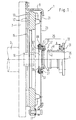
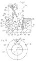
- the friction clutch 1 schematically shows a drive train of a motor vehicle between its internal combustion engine and transmission arranged friction clutch 1.
- the friction clutch 1 includes a coaxial on a crankshaft 3 of the internal combustion engine to the axis of rotation 5 attached flywheel 7, a on Flywheel 7 held clutch housing 9, on which Tangential leaf springs 11 but a pressure plate 13 rotatably is guided axially movable. Between the pressure plate 13 and the flywheel 7 is a clutch disc 15 with its friction linings 17 can be clamped.
- the clutch disc 15 has a hub 19 with a transmission input shaft, not shown one of the crankshaft 3 or the internal combustion engine axially opposite gearbox of the motor vehicle can be coupled.
- the flywheel 7 and / or the clutch disc 15 can in a conventional manner with a torsional vibration damper be provided.
- a clutch main spring here a diaphragm spring 21 clamped, which a variety of whose inner circumference protrudes radially inwards by radially running slots separate spring tongues 23 Has.
- the diaphragm spring 21 tensions the friction linings 17 of the clutch disc 15 between the pressure plate 13 and the flywheel 7 a.
- the spring tongues 23 form disengagement elements, via the friction clutch 1 can be disengaged if the Spring tongues 23 by means of a generally designated 25 Release arrangement in the direction of arrow A from the flywheel 7 be pulled away.
- the Diaphragm spring 21 with its outer circumference on the clutch housing 9 and on a smaller diameter on the pressure plate 13 from. Components acting on the release arrangement 25 Clutch actuation systems are not shown.
- the release assembly 25 includes one on the radially inner one Ends of a central passage opening 27 for the not Spring tongues defining the gear input shaft shown in more detail 23 attached release ring 29 and a release bearing 31 with a non-rotating outer bearing ring 33, on which the clutch actuation system, not shown attacks and a rotating inner bearing ring 35.
- the rotating bearing ring 35 is generally indicated at 37
- Snap connection means can be coupled to the disengaging ring 29.
- Fig. 1 shows the snap connection means 37 before Assembly while Fig. 2 shows the closed snap connection means shows.
- To form the snap connection means 37 is on the inner circumference of the disengaging ring 29 towards the disengaging bearing 31 tapering, essentially conical power transmission ring surface 39 integrally formed, while the rotating bearing ring 35 its outer circumference is curved toward the crankshaft or conically extending power transmission ring surface 41 has.
- the power transmission ring surface 41 settles to the crankshaft end of the inner bearing ring 35 in a tapered conical surface 43.
- Release ring 29 is a radially resilient load transmission ring 45 arranged, as best shown in FIG. 2, when closed Snap connection means 37 between the power transmission ring surfaces 39, 41, so that the release force in Direction of arrow A from the release bearing 31 on the spring tongue 23 can be transmitted.
- the release ring 29, as shown in FIG. 2, essentially has one axially extending ring portion 47, the inner periphery the power transmission ring surface 39 forms and one the spring tongues 23 engaging radially on the motor side protruding, substantially annular flange 49.
- the release ring 29 engages with several, in the circumferential direction distributed claws 51 through the slots between adjacent ones Spring tongues 23 and is on the transmission side of the Spring tongues 23 by means of one engaging in the claws Retaining rings 53 attached to the spring tongues 23.
- the load transfer ring 45 is designed as an open, radially resilient ring, the ends 55 of which, as best shown in FIG.
- the load transmission ring lies before the release bearing 31 is installed 45 substantially loosely in the ring area 47 assembly, the inner bearing ring 35 is in the ring area 47 inserted, the conical surface 43 with its section 57 on the edge 65 of the opening 59 load transmission ring 45 expands until the load transmission ring 45 due to its internal stress behind the load transmission ring surface 41 snaps.
- the release bearing 31 can then in Direction of arrow A until the load transfer ring 45 also contacts the load transmission ring surface 39. With the snap connection closed in this way The ends 55 of the load transmission ring 45 run without contact both through the opening 49 and without contact related to the other components of the release arrangement 25th
- a diaphragm spring 67 is provided on its outer circumference is held on the flange 49 by means of a support ring 69 and with their spring tongues 71 under tension on the motor side Front end of the rotating inner bearing ring 35 of the release bearing 31 is present.
- the diaphragm spring 67 thus loads independently possible forces of the clutch actuation system the snap connection means 37 in the closing direction. Despite possible vibrations of the internal combustion engine thus a permanent contact of the snap connection means 37 guaranteed.
- the flange 49 lies with a curvature to reduce wear 73 on the spring tongues 23.
- the curvature 73 settles radially inward into an opposite, second curvature 75 while moving radially outward from the spring tongues 23 extends axially away.
- the diaphragm spring 67 by means of a support edge 77 engaging support ring 69 in this way by flanging on the outer circumference of the flange 49 of the release ring 29 are attached.
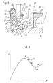
- FIG. 3 shows the spring force-spring travel characteristic of the diaphragm spring 67, the spring force F of which initially increases with a increasing spring travel s to a maximum force value F max , then decreases along a falling branch 79 to a minimum value F min and then increases again.
- the diaphragm spring 67 is installed in such a way that it is pretensioned to a value F 1 of the descending branch 79 when the release bearing 31 is not yet assembled, so that the maximum force F max has already been overcome.
- F 2 denotes the preload of the diaphragm spring 67 when the release bearing 31 is installed. This value is also on the descending branch 79 of the characteristic curve, but shifted towards the minimum F min . The preload force of the diaphragm spring 67 is thus reduced during the assembly of the release bearing, which facilitates the assembly.
- the bearing ring 35 is pushed in beyond the operating position determined by F 2 , the preload of the diaphragm spring 67 being able to increase slightly beyond F min to the subsequent, rising branch up to the preload F 3 .
- the release bearing 31 moves back in the direction of arrow A due to the preload of the diaphragm spring 67, as a result of which the preload increases again to the value F 2 .
- the spring force F 2 is sufficient to ensure a secure contact between the load transmission ring 45 and the force transmission ring surfaces 39, 41 during operation of the friction clutch, so that no wear can occur at this point. Due to the preload of the diaphragm spring 67 before assembly of the release bearing 31, it is ensured that no unfavorably high spring forces have to be overcome during the assembly process.
- a clutch main spring which is equipped with separate release levers.
- load transmission ring 45 and its Ends 55 differ from the illustrated embodiment and also the fixing of the release ring 29 on the release elements can be solved differently, without the basic idea of the invention, the detachable snap connection by an additional To preload the tensioning element within itself.
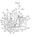
- the release arrangement 25a from FIG. 4 differs from the arrangement of FIG. 2 primarily in that the again by a disc-shaped spring, for example a plate spring, but here a diaphragm spring 67a is formed
- Preload element on the gear side of the spring tongues 23a is arranged and over a rotating inner Bearing ring 35a surrounding disk 81 with its inner circumference on an axial end face 83 of the ring region 47a of the release ring 29a supports.
- the diaphragm spring 67a With its outer circumference is the diaphragm spring 67a supported on a disc 85, which in turn on one facing the end face 83 of the disengagement ring 29a Paragraph 87 of the bearing ring 35a is supported.
- the disk 85 carries centering means 89 for the diaphragm spring on its outer circumference 67a. Due to its slightly conical shape, the diaphragm spring 67a in the construction space radially within the axial Bends 61a of the ends 55a of the load transmission ring 45a reach into what the space required in the axial direction the release assembly 25a reduced.
- the disc 81 can optionally be omitted if the diaphragm spring 67a rests directly on the end face 83.
- the Disc 81 on the one hand, enables larger radial diameter changes the inner circumference of the diaphragm spring 67a their travel and on the other hand, the disk 81, as in Fig. 4 shown for the axial securing and pre-assembly of the Diaphragm spring 67a on the bearing ring 35a can be used.
- the inner ring 35a is related to a paragraph referring to paragraph 87 91 provided, via which the disk 81 under elastic Deformation with its inner diameter is snapped.
- the remaining travel shown at 93 is the Diaphragm spring 67a is kept larger with the release bearing 31a installed than the distance shown at 95 between the Edge 65a and the section striking against it during assembly 57a of the ends 55a of the load transmission ring 45a.
- the spring travel 93 is sufficient to the load transmission ring 45a over the conical surface 43a into the one in FIG. 4 bring shown operating position. Travel 93 can in this way analogously to the embodiment of FIG. 2 used to close the snap fastener to be carried out on the sloping branch of the spring characteristic.
- the disk 85 runs in front of one with a narrow axial distance Sealing disc 97, which is located on the outer bearing ring 33 on the the side facing the release ring 29a radially to close to the inner bearing ring 35a extends.
- the disks 85, 97 form a labyrinth seal for the release bearing 31a, wherein the disk 85 in addition to its support and centering function has a sealing function.
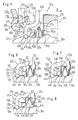
- the release arrangements shown in Figs. 5 to 8 differ from the arrangement of FIG. 4 in the first Line in that instead of a single plate or diaphragm spring two such spring elements are provided are supported on each other on their outer circumference and with its inner circumference between the release ring on the one hand or the inner ring of the release bearing on the other hand are. It is understood that, if necessary, several of these Spring pairs can be arranged in series one behind the other.
- Fig. 5 shows two plate or diaphragm spring-shaped spring elements 67b, which is located on its outer circumference via an intermediate washer Support 99 against each other.
- the intermediate plate 99 enables a defined support of the two spring elements 67b to each other.
- the disk 81b supports the spring element on the motor side 67b on the end face 83b of the release ring 29b from and holds the spring elements 67b captively on the bearing ring 35b.
- the Disc 85b has a smaller diameter than in the variant 4 and is only used to support the transmission side Spring element 67b and for sealing the Release bearing 31b used.
- a plurality of spring elements 67b can have their outer diameter are kept so small that they are essentially radially inside of the through the axially extending portion 61b Ends 55b of the load transmission ring 45b run. This makes possible an axially and radially very space-saving accommodation the spring elements 67b.
- the release arrangement 25c according to FIG. 6 differs of the arrangement of Fig. 5 primarily in that instead of the washer which in turn as a plate or Membrane spring formed spring elements 67c on its outer circumference several circumferentially offset, axially projecting tabs 101, which in between spaces the tab 101 of the respective other spring element 67c grip and bring the spring elements 67c radially together.
- the gear-side spring element 67c can, as indicated in FIG. 6, if necessary on the shoulder 87c of the bearing ring 35c be centered.
- the disks are located in the release arrangement 25d in FIG. 7 or diaphragm spring-like spring elements 67d in the area of their Outer circumference directly to each other and are radial to each other Direction through axially extending tabs 103 one of the spring elements 67d separate component, here the Supporting spring element 67d on the motor side on the end face 83d Disc 81d, centered relative to each other.
- the total centering the arrangement can again here on the transmission side Spring element 67d on the shoulder 87d of the bearing ring 35d.
- the disk 81d can, as in the above 4 to 6 described variants for the axial Securing and pre-assembly of the spring elements used become.
- FIGS. 4 to 7 are the spring elements on the inner, rotating bearing ring of the Release bearing pre-assembled or axially secured.
- Fig. 8 shows a variant in which on the outer circumference of the ring area 47e of the disengagement ring 29e axially fixed a centering plate 105 is placed on its outer circumference several in the circumferential direction offset, projecting axially towards the release bearing Rag 107 carries.
- the tabs 107 overlap on their Outer circumference supported, plate-like or diaphragm-like Spring elements 67e and center them relatively to each other and to the release ring 29e.
- the release ring 29e Ends 109 of the tabs 107 are facing radially inward bent and secure the spring elements 67e in the axial direction. While the gear-side spring element 67e in turn on a disk 85e supported on the bearing ring 35e with its The inner spring element is supported 67e directly on the end face 83e of the ring area 47e on.
- the attachment of the release ring 29 according to FIG. 1 at the ends of the diaphragm spring tongues 23 can from the flange 49 of the release ring 29 several distributed in the circumferential direction Tongues in the axial direction.
- the tongues grip here in the radial slots between adjacent Diaphragm spring tongues 23 and fix the release ring 29 rotatably on the diaphragm spring tongues 23.
- For axial fixation can have an annular spring element on the release bearing 31 facing side of the spring tongues 23 arranged be, that with several, circumferentially distributed tongues reaches through the slots between the diaphragm spring tongues 23 and the flange 49 of the release ring 29 from radial reaches outside. It is understood that this type of The release ring is also fixed to the diaphragm spring tongues the variants of FIGS. 2 to 10 can be used.
- this is for bracing the snap connection means provided resilient biasing element between the Diaphragm spring tongues held release ring on the one hand and one supported on the rotating inner bearing ring of the release bearing Disc on the other hand clamped.
- the following will be Embodiments explained in which the biasing element directly between the diaphragm spring tongues and the aforementioned Disc is clamped. Even in these cases the biasing element is formed so that it the ends of the Load transfer ring of the snap connection means in operation contact-free from other components of the release arrangement can hold and at the same time for releasing the snap connection means keeps accessible.
- FIGS. 9 and 10 show a release arrangement 25h, the Release ring 29h with lugs 133h that between adjacent Grab spring tongues 23h, is provided and by means of an annular Spring element 135h and its between the spring tongues 23h through tongues 137h on the spring tongues 23h is fixed.
- the lugs 133h can be kept so short that the spaces between the spring tongues 23h do not fill in completely.
- the ends 55h of the load transmission ring 45h reach through the axially extending area 47h provided opening 59h, whereby the load transmission ring 45h compared to 23h on the diaphragm spring tongues positioned release ring 29h is in turn positioned.
- the opening 59h is similar to the variants previously described axially closed, causing the load transmission ring 45h is held captive on the release ring 29h.
- the snap connection means 37h are by a plate spring 67h axially clamped.
- the plate spring contains 67h in it otherwise essentially closed surface one for Rotation axis 5h concentric slot 131h, through the ends 55h of the load transmission ring 45h without contact step through so that they can be operated from the outside.
- the plate spring 67h has several distributed on its outer circumference axially protruding lugs 139, which also enter the gaps engage between adjacent diaphragm spring tongues and the assignment of the slot 13lh to the ends 55h of the load transmission ring Ensure 45h.
- the plate spring is 67h on their outer circumference on the one hand and their inner circumference on the other hand provided with support arches 141 and 143, respectively which they attach themselves to the membrane spring tongues on their outer circumference 23h and on its inner circumference on the inner bearing ring 35h at 85h supported disc 85h.
- the curvature 141 am
- the outer edge of the plate spring 67h encompasses a spring element 145, that extends with claws 147 between the diaphragm spring tongues 23h and embraces it from the back.
- the washer supported on the shoulder 87h of the bearing ring 35h 85h again forms together with the cover plate 97h of the outer bearing ring 33h a labyrinth seal.
- FIGS. 9 and 10 show a variant of arrangements of FIGS. 9 and 10 show a disengagement arrangement 25i which differs from that Arrangement differs only in that instead the diaphragm spring 67h with a diaphragm spring 67i with radial internal spring tongues 149 for the axial bracing of the Snap connection means 37i between the diaphragm spring tongues 23i and the disk 85i supported on the inner bearing ring 35i is clamped.
- the diaphragm spring 67i is rotationally symmetrical built up, the spring tongues 149 by radially extending Slots 151 are separated.
Landscapes
- Engineering & Computer Science (AREA)
- General Engineering & Computer Science (AREA)
- Mechanical Engineering (AREA)
- Mechanical Operated Clutches (AREA)
Description
- einen konzentrisch zur Drehachse an den Ausrückelementen befestigten, auf der Motorseite der Ausrückelemente abgestützten Ausrückring,
- ein in Richtung der Drehachse bewegliches Ausrücklager mit einem rotierenden, insbesondere inneren Lagerring und einem nicht rotierenden, insbesondere äußeren Lagerring und
- axial miteinander kuppelbare Schnappverbindungsmittel zwischen dem Ausrückring und dem rotierenden Lagerring, umfassend Kraftübertragungsflächen, insbesondere angenähert konisch verlaufende Kraftübertragungs-Ringflächen an dem Ausrückring und dem rotierenden Lagerring und wenigstens ein radial federndes Lastübertragungselement, insbesondere in Form eines radial federnden Lastübertragungsrings, welches zwischen die Kraftübertragungsflächen schnappbar ist, wobei zwischen dem Ausrückring oder den Ausrückelementen einerseits und dem rotierenden Lagerring andererseits ein im wesentlichen axial federndes Vorspannelement eingespannt ist, welches die Schnappverbindungsmittel axial gegeneinander vorspannt und wenigstens ein im wesentlichen ringförmiges, axial federndes, zur Drehachse konzentrisches und als Tellerfeder oder als Membranfeder mit radial abstehenden Federzungen ausgebildetes Federelement umfaßt.
- Fig. 1
- einen teilweisen Axiallängsschnitt durch eine Kraftfahrzeug-Reibungskupplung mit einer erfindungsgemäßen Ausrückeranordnung, deren Schnappverbindungsmittel durch eine auf der Motorseite eines Ausrückrings angeordnete Membranfeder vorspannbar ist;
- Fig. 2
- eine Detaildarstellung der Ausrückeranordnung;
- Fig. 3
- ein Diagramm mit einer die Federkraft F in Abhängigkeit vom Federweg s repräsentierenden Kennlinie einer Vorspann-Membranfeder;
- Fig. 4 bis 8
- Detaildarstellungen von Varianten der Ausrückeranordnung mit zwei auf der Getriebeseite des Ausrückrings angeordneten Vorspann-Membranfedern
- Fig. 9
- einen teilweisen Axiallängsschnitt durch eine Variante einer Ausrückerandordnung, bei welcher Enden eines Lastübertragungsrings durch eine Öffnung einer die Schnappverbindung vorspannenden Tellerfeder geführt sind;
- Fig. 10
- eine Axialansicht der Tellerfeder aus Fig. 9;
- Fig. 11
- einen teilweisen Axiallängsschnitt durch eine Variante der Ausrückeranordnung mit einer die Schnappverbindung vorspannenden Membranfeder; und
- Fig. 12
- eine Axialansicht der Membranfeder aus Fig. 11.
Claims (29)
- Ausrückeranordnung für eine im Antriebsstrang zwischen einer Brennkraftmaschine und einem Getriebe eines Kraftfahrzeugs angeordnete Reibungskupplung (1), deren zusammen mit der Reibungskupplung (1) um eine Drehachse (5) rotierende, insbesondere durch Federzungen einer Membranfeder (21) gebildete, im wesentlichen radial zur Drehachse (5) hin sich erstreckende Ausrückelemente (23) zum Ausrücken der Reibungskupplung (1) zum Getriebe hin bewegbar sind, umfassendwobei zwischen dem Ausrückring (29) oder den Ausrückelementen (23) einerseits, und dem rotierenden Lagerring (35) andererseits ein im wesentlichen axial federndes Vorspannelement (67) eingespannt ist, welches die Schnappverbindungsmittel (39) axial gegeneinander vorspannt und wenigstens ein im wesentlichen ringförmiges, axial federndes, zur Drehachse (5) konzentrisches und als Tellerfeder oder als Membranfeder mit radial abstehenden Federzungen ausgebildetes Federelement (67) umfaßt,einen konzentrisch zur Drehachse (5) an den Ausrückelementen (23) befestigten, auf der Motorseite der Ausrückelemente (23) abgestützten Ausrückring (29),ein in Richtung der Drehachse (5) bewegliches Ausrücklager (31) mit einem rotierenden, insbesondere inneren Lagerring (35) und einem nicht rotierenden, insbesondere äußeren Lagerring (33) undaxial miteinander kuppelbare Schnappverbindungsmittel (39) zwischen dem Ausrückring(29) und dem rotierenden Lagerring (35), umfassend Kraftübertragungsflächen (39, 41), insbesondere angenähert konisch verlaufende Kraftübertragungs-Ringflächen an dem Ausrückring (29) und dem rotierenden Lagerring (35) und wenigstens ein radial federndes Lastübertragungselement (45), insbesondere in Form eines radial federnden Lastübertragungsrings, welches zwischen die Kraftübertragungsflächen (39, 41) schnappbar ist,
dadurch gekennzeichnet,
daß das Federelement (67) mit einer Vorspannung angeordnet ist, deren Wert bei nicht miteinander gekuppelten Schnappverbindungsmitteln (37) so bemessen ist, daß sowohl dieser Wert der Vorspannung als auch der Wert der Vorspannung des Federelements (67) bei miteinander gekuppelten Schnappverbindungsmitteln (37) auf einem Ast (79) der Federkraft-Federweg-Kennlinie des Federelements (67) liegen, in welchem die Federkraft mit wachsendem Federweg abnimmt. - Ausrückeranordnung nach Anspruch 1, dadurch gekennzeichnet, daß zum Schließen der Schnappverbindung die Schnappverbindungsmittel (37) über deren gekuppelte Stellung hinaus relativ zueinander in eine Schließstellung zu bewegen sind, in der der Wert die Vorspannung des Federelementes (67) ein Minimum der Kennlinie durchlaufen hat.
- Ausrückeranordnung nach Anspruch 2, dadurch gekennzeichnet, daß das Federelement (67) auf der Motorseite des Ausrückrings (29) angeordnet ist, im Bereich seines Außenumfangs an dem Ausrückring (29) gehalten ist und im Bereich seines Innenumfangs am rotierenden Lagerring (35) abgestützt ist.
- Ausrückeranordnung nach Anspruch 3, dadurch gekennzeichnet, daß der Ausrückring (29) einen angenähert radial abstehenden, im wesentlichen ringförmigen Flansch (49) hat, mit dem er auf der Motorseite der Ausrückelemente (23) aufliegt sowie einen im wesentlichen axial sich erstreckenden Ringbereich (47) aufweist, der in eine von den Ausrückelementen (23) radial begrenzte, zentrische Öffnung (27) hineinreicht und aut seiner inneren Umfangsfläche die Kraftübertragungs-Ringfläche (39) des Ausrückrings (29) bildet und daß am Außenumfang des Flansches (49) ein Stützring (69), insbesondere in Form eines um den Flansch herum gebördelten Blechrings angeordnet ist, der in axialem Abstand zum Flansch (49) eine ringförmige Stützkante (77) für die Abstützung des Federelements (67) aufweist.
- Ausrückeranordnung nach Anspruch 4, dadurch gekennzeichnet, daß der Flansch (49) des Ausrückrings (29) mit einer ersten Wölbung (73) an den Ausrückelementen (23) anliegt, und daß die erste Wölbung (73) zur Drehachse (5) hin in eine zweite entgegengesetzte Wölbung (75) übergeht, an der das Federelement (67) bei nicht miteinander gekuppelten Schnappverbindungsmitteln (37) vorgespannt anliegt.
- Ausrückeranordnung nach Anspruch 1, dadurch gekennzeichnet, daß das Vorspannelement (67a-e, h, i) auf der Getriebeseite der Ausrückelemente (23a-e, h, i) angeordnet ist, daß der Ausrückring (29a-e) einen angenähert radial abstehenden, im wesentlichen ringförmigen Flansch (49a-e) hat, mit dem er auf der Motorseite der Ausrückelemente (23a-e) aufliegt sowie einen im wesentlichen axial sich erstreckenden Ringbereich (47a-e) aufweist, der in eine von den Ausrückelementen (23a-e) radial begrenzte, zentrische Öffnung (27a-e) hineinreicht, eine zum Ausrücklager (31a-e) weisende axiale Stirnfläche (83, 83a-e) hat und auf seiner inneren Umfangsfläche die Kraftübertragungs-Ringfläche (39a-e) des Ausrückrings (29a-e) bildet, und daß das Vorspannelement (67a-e) zwischen der Stirnfläche (83, 83b-e) des Ausrückrings (29a-e) und einer axial entgegengerichteten Fläche (87; 87b-e) des rotierenden Lagerrings (35a-e) eingespannt ist.
- Ausrückeranordnung nach Anspruch 6, aaaurcn gekennzeichnet, daß zumindest das eine Federelement (67a-e) als im wesentlichen ringscheibenförmige Tellerfeder oder Membranfeder ausgebildet ist, die mit ihrem Innenumfang an der axialen Stirnfläche (83; 83b-e) des Ausrückrings (29a-e) abgestützt ist.
- Ausrückeranordnung nach Anspruch 7, dadurch gekennzeichnet, daß der rotierende Lagerring (35a) eine ringförmige Scheibe (85) trägt, die sich an einem axial zur Stirnfläche (83) des Ausrückrings (29a) weisenden Absatz (87a) des rotierenden Lagerrings (35a) abstützt und daß das Vorspannelement (67a) ein einziges Federelement (67a) aufweist, das sich mit seinem Außenumfang an der Scheibe (85) abstützt.
- Ausrückeranordnung nach Anspruch 8, dadurch gekennzeichnet, daß die Scheibe (85) an ihrem Außenumfang Zentriermittel (89) für das Federelement (67a) aufweist.
- Ausrückeranordnung nach Anspruch 7, dadurch gekennzeichnet, daß das Vorspannelement wenigstens ein Paar als Tellerfeder oder Membranfeder ausgebildete Federelemente (67b-e) aufweist, die sich an ihrem Außenumfang aneinander abstützen, und von denen ein erstes Federelement (67b-e) mit seinem Innenumfang an der Stirnfläche (83b-e) des Ausrückrings (29b-e) und ein zweites Federelement (67b-e) mit seinem Innenumfang an dem rotierenden Lagerring (35b-e) abgestützt ist.
- Ausrückeranordnung nach Anspruch 10, dadurch gekennzeichnet, daß axial zwischen dem ersten und dem zweiten Federelement (67b) eine ringförmige Zwischenscheibe (99) angeordnet ist.
- Ausrückeranordnung nach Anspruch 10, dadurch gekennzeichnet, daß das erste und zweite Federelement (67c) an ihrem Außenumfang axial abstehende Lappen (101) tragen, die in Aussparungen am jeweils anderen Federelement (67c) eingreifen.
- Ausrückeranordnung nach einem der Ansprüche 10 bis 12, dadurch gekennzeichnet, daß axial zwischen dem zweiten Federelement (67b-e) und einem zur Stirnfläche (83b-e) des Ausrückrings (29b-e) weisenden Absatz (87b-e) des rotierenden Lagerrings (35b-e) eine ringförmige Scheibe (85b-e) angeordnet ist.
- Ausrückeranordnung nach einem der Ansprüche 7 bis 13, dadurch gekennzeichnet, daß axial zwischen der Stirnfläche (83; 83b-d) des Ausrückrings (29a-d) und dem mit seinem Innenumfang an der Stirnfläche (83; 83b-d) abgestütztem Federelement (67a-d) eine ringförmige Stützscheibe (81; 81b-d) angeordnet ist, und daß der rotierende Lagerring (35a-d) auf der dem Federelement (67a-d) abgewandten Seite der Stützscheibe (81; 81b-d) einen die Stützscheibe (81; 81b-d) axial sichernden Absatz (91; 91b-d) aufweist.
- Ausrückeranordnung nach Anspruch 14, dadurch gekennzeichnet, daß das Lastübertragungselement (45a-d) und der Ausrückring (29a-d) einander zugeordnete Anschläge (57a-d, 65a-d) bilden, die das axiale Bewegungsspiel des Lastübertragungselements (45a-d) zum Ausrücklager (31a-d) hin beim Schließen der Schnappverbindungsmittel (37a-d) auf einen Maximalwert begrenzen, der kleiner ist als ein bei geschlossenen Schnappverbindungsmitteln (37a-d) verbleibender Restfederweg des Federelements (67a-d).
- Ausrückeranordnung nach Anspruch 14 oder 15, dadurch gekennzeichnet, daß vom Außenumfang der Stützscheibe (81d) Lappen (103) axial abstehen, die den Außenumfang jedes Federelements (67d) zu dessen Zentrierung übergreifen.
- Ausrückeranordnung nach einem der Ansprüche 7 bis 14, dadurch gekennzeichnet, daß auf dem axial sich erstreckenden Ringbereich (47e) des Ausrückrings (29e) im Bereich von dessen Stirnfläche (83e) ein Zentrierteil (105), insbesondere ein Zentrierblechteil aufgesetzt ist, von dem Lappen (107) im wesentlichen axial abstehen, die den Außenumfang jedes Federelements (67e) zu dessen Zentrierung übergreifen.
- Ausrückeranordnung nach Anspruch 17, dadurch gekennzeichnet, daß die Lappen (107) nach radial innen gebogene Enden (109) zur Sicherung des Federelements (67e) bei Vormontage am Ausrückring (29e) haben.
- Ausrückeranordnung nach einem der Ansprüche 7 bis 18, dadurch gekennzeichnet, daß der Lastübertragungsring (45a-e) als offener Ring ausgebildet ist, dessen Enden (55a-e) zunächst im wesentlichen in der Ebene des offenen Rings angenähert radial nach außen verlaufen, dann axial zum Ausrücklager (31a-e) hin abgebogen sind, um dann erneut nach radial außen zu verlaufen, und daß zumindest das mit seinem Innenumfang an der axialen Stirnfläche (83; 83b-e) des Ausrückrings (29a-e) abgestützte Federelemente (67a-e) mit dem axial abgebogenen Bereich (61a-e) der beiden Enden (55a-e) des Lastübertragungsrings (45a-e) axial überlappt.
- Ausrückeranordnung nach Anspruch 6, dadurch gekennzeichnet, daß der Ausrückring (29h, i) einen angenähert radial abstehenden, im wesentlichen ringförmigen Flansch (49h, i) hat, mit dem er auf der Motorseite der Ausrückelemente (23h, i) aufliegt, sowie einen im wesentlichen axial sich erstreckenden Ringbereich (47h, i) aufweist, der in eine von den Ausrückelementen (23h, i) radial begrenzte, zentrische Öffnung (131h, i) hineinreicht und auf seiner inneren Umfangsfläche die Kraftübertragungs-Ringfläche (39h, i) des Ausrückrings (29h, i) bildet, daß der Lastübertragungsring (45h, i) als offener Ring ausgebildet ist, dessen Enden (55h, i) zum Lösen der Schnappverbindungsmittel (37h, i) zumindest angenähert in den Raum axial zwischen dem Bereich der die zentrische Öffnung (27h, i) begrenzenden Enden der Ausrückelemente (23h, i) und dem Ausrücklager (31h, i) hineinreichen, und daß das Vorspannelement (67h, i) einen Durchlaßraum (131h, i) bildet oder begrenzt, durch den hindurch die Enden (55h, i) insbesondere berührungsfrei radial nach außen geführt sind.
- Ausrückeranordnung nach Anspruch 20, dadurch gekennzeichnet, daß das Vorspannelement (67h, i) sich im Bereich seines Außenumfangs direkt an den Ausrückelementen (23h, i) und im Bereich seines Innenumfangs an dem rotierenden Lagerring (35h, i) abstützt.
- Ausrückeranordnung nach Anspruch 21, dadurch gekennzeichnet, daß die Öffnung (131h) des Federeiements (67h) für den Durchtritt der Enden (55h) des Lastübertragungsrings (45h) als zur Drehachse (5h) konzentrisch verlaufender Schlitz ausgebildet ist.
- Ausrückeranordnung nach Anspruch 21, dadurch gekennzeichnet, daß die Membranfeder (67i) radial nach innen ragende, durch radiale Schlitze (15)1 getrennte Federzungen (149) aufweist und daß die Enden (55i) des Lastübertragungsrings (45i) durch zumindest einen in Umfangsrichtung verbreiterten (131i) dieser Schlitze radial nach außen geführt sind.
- Ausrückeranordnung nach Anspruch 23, dadurch gekennzeichnet, daß die Membranfeder (67i) mehrere in gleichen Winkelabständen voneinander angeordnete verbreiterte Schlitze (131i) hat.
- Ausrückeranordnung nach einem der Ansprüche 21 bis 24, dadurch gekennzeichnet, daß vom Außenumfang des Federelements (67h; i) Nasen (139; 139i) axial abstehen, die zwischen die Ausrückelemente (23h, i) greifen und das Federelement (67h, i) verdrehfest fixieren.
- Ausrückeranordnung nach einem der Ansprüche 21 bis 25, dadurch gekennzeichnet, daß das Federelement (67h, i) im Abstützbereich seines Innenumfangs und seines Außenumfangs zur Verschleißminderung entgegengesetzt gewölbt ist.
- Ausrückeranordnung nach Anspruch 26, dadurch gekennzeichnet, daß der rotierende Lagerring (35h, i) des Ausrücklagers (31h, i) eine ringförmige Scheibe (85h, i) trägt, die sich an einem axial zur Stirnfläche des Ausrückrings (29h, i) weisenden Absatz (87h, i) des rotierenden Lagerrings (35h, i) unmittelbar neben dem Ausrücklager (31h, i) abstützt und an der sich seinerseits das Federelement (67h, i) mit seinem inneren Bereich abstützt.
- Ausrückeranordnung nach Anspruch 26 oder 27, dadurch gekennzeichnet, daß das Federelement (67h, i) im Bereich seines Außenumfangs an den Ausrückelementen (23h, i) mittels Haltefedern (145; 145i) fixiert ist.
- Ausrückeranordnung nach einem der Ansprüche 1 bis 28, dadurch gekennzeichnet, daß der nicht rotierende, äußere Lagerring (33; 33a, b, h, i) auf seiner den Ausrückelementen (23; 23a-e, h, i) zugewandten Seite eine nach radial innen reichende, in geringem Abstand vom rotierenden, inneren Lagerring (35; 35a-e, h, i) endende Deckscheibe (97; 97a-e, h i) trägt, und daß am rotierenden Lagerring (35; 35a-e, h, i) eine in geringem Abstand zur Deckscheibe (97; 97a-e, n, i) angeordnete Scheibe (85; 85a-e, h, i) angeordnet ist, die zusammen mit der Deckscheibe (97; 97a-e, h, i) eine Labyrinthdichtung bildet und an der das Vorspannelement (67; 67a-e, h, i) axial abgestützt ist.
Applications Claiming Priority (9)
| Application Number | Priority Date | Filing Date | Title |
|---|---|---|---|
| DE4211477A DE4211477C2 (de) | 1992-04-06 | 1992-04-06 | Reibungskupplung mit verspannter Schnappverbindung |
| DE4211476 | 1992-04-06 | ||
| DE4211476 | 1992-04-06 | ||
| DE4211478A DE4211478C2 (de) | 1992-04-06 | 1992-04-06 | Reibungskupplung mit verspannter Schnappverbindung |
| DE4211478 | 1992-04-06 | ||
| DE4211477 | 1992-04-06 | ||
| DE4303489A DE4303489A1 (de) | 1992-04-06 | 1993-02-06 | Reibungskupplung mit verspannter Schnappverbindung |
| DE4303489 | 1993-02-06 | ||
| EP93105700A EP0565063B1 (de) | 1992-04-06 | 1993-04-06 | Ausrückeranordnung für eine Kraftfahrzeug-Reibungskupplung |
Related Parent Applications (2)
| Application Number | Title | Priority Date | Filing Date |
|---|---|---|---|
| EP93105700.4 Division | 1993-04-06 | ||
| EP93105700A Division EP0565063B1 (de) | 1992-04-06 | 1993-04-06 | Ausrückeranordnung für eine Kraftfahrzeug-Reibungskupplung |
Publications (3)
| Publication Number | Publication Date |
|---|---|
| EP0709591A2 EP0709591A2 (de) | 1996-05-01 |
| EP0709591A3 EP0709591A3 (de) | 1996-05-29 |
| EP0709591B1 true EP0709591B1 (de) | 1999-12-01 |
Family
ID=27435430
Family Applications (2)
| Application Number | Title | Priority Date | Filing Date |
|---|---|---|---|
| EP93105700A Expired - Lifetime EP0565063B1 (de) | 1992-04-06 | 1993-04-06 | Ausrückeranordnung für eine Kraftfahrzeug-Reibungskupplung |
| EP95117531A Expired - Lifetime EP0709591B1 (de) | 1992-04-06 | 1993-04-06 | Ausrückeranordnung für eine Kraftfahrzeug-Reibungskupplung |
Family Applications Before (1)
| Application Number | Title | Priority Date | Filing Date |
|---|---|---|---|
| EP93105700A Expired - Lifetime EP0565063B1 (de) | 1992-04-06 | 1993-04-06 | Ausrückeranordnung für eine Kraftfahrzeug-Reibungskupplung |
Country Status (3)
| Country | Link |
|---|---|
| EP (2) | EP0565063B1 (de) |
| BR (1) | BR9301458A (de) |
| DE (2) | DE59302649D1 (de) |
Families Citing this family (3)
| Publication number | Priority date | Publication date | Assignee | Title |
|---|---|---|---|---|
| DE19548859C1 (de) * | 1995-12-27 | 1997-02-20 | Fichtel & Sachs Ag | Verliersichere Vorlastfeder |
| FR2944770B1 (fr) * | 2009-04-27 | 2012-12-14 | Peugeot Citroen Automobiles Sa | Dispositif de montage d'un organe de friction et procede de montage de l'organe sur un arbre. |
| DE202010016772U1 (de) * | 2010-11-23 | 2011-03-24 | Zf Friedrichshafen Ag | Ausrückeinrichtung für eine gezogene Kraftfahrzeugkupplung |
Family Cites Families (11)
| Publication number | Priority date | Publication date | Assignee | Title |
|---|---|---|---|---|
| FR834298A (fr) * | 1937-02-27 | 1938-11-16 | Gen Motors Corp | Embrayage à friction perfectionné |
| FR2539473B1 (fr) * | 1983-01-17 | 1986-04-11 | Valeo | Montage de butee de debrayage, et mecanisme d'embrayage comportant une piece d'accostage propre a un tel montage |
| FR2544039B1 (de) | 1983-04-11 | 1986-06-27 | Valeo | |
| GB8404519D0 (en) * | 1984-02-21 | 1984-03-28 | Automotive Prod Plc | Friction clutch for vehicle |
| DE3537788C2 (de) | 1985-10-24 | 1994-02-10 | Fichtel & Sachs Ag | Schnappverbindung für eine gezogene Membranfederkupplung |
| FR2622265B1 (fr) | 1987-10-22 | 1991-09-20 | Automotive Prod France | Mecanisme de debrayage notamment pour embrayage de vehicule |
| FR2629882B1 (fr) * | 1988-04-08 | 1993-01-29 | Valeo | Montage de butee de debrayage, notamment pour vehicule automobile |
| FR2633354B1 (fr) | 1988-06-23 | 1993-04-09 | Valeo | Montage pour l'assujettissement d'une piece d'accostage a un diaphragme, notamment pour vehicule automobile |
| FR2633353B1 (fr) | 1988-06-23 | 1992-12-24 | Valeo | Ensemble d'accostage pour butee de debrayage, notamment pour vehicule automobile |
| KR930004649A (ko) * | 1991-08-17 | 1993-03-22 | 원본미기재 | 당김형태 마찰 클러치의 부정합체계 |
| FR2688039B1 (fr) * | 1992-02-28 | 1998-06-26 | Valeo | Montage de butee de debrayage, notamment pour vehicule automobile. |
-
1993
- 1993-04-06 BR BR9301458A patent/BR9301458A/pt not_active IP Right Cessation
- 1993-04-06 EP EP93105700A patent/EP0565063B1/de not_active Expired - Lifetime
- 1993-04-06 EP EP95117531A patent/EP0709591B1/de not_active Expired - Lifetime
- 1993-04-06 DE DE59302649T patent/DE59302649D1/de not_active Expired - Fee Related
- 1993-04-06 DE DE59309892T patent/DE59309892D1/de not_active Expired - Fee Related
Also Published As
| Publication number | Publication date |
|---|---|
| DE59309892D1 (de) | 2000-01-05 |
| BR9301458A (pt) | 1993-10-13 |
| EP0565063A2 (de) | 1993-10-13 |
| EP0709591A3 (de) | 1996-05-29 |
| EP0565063A3 (de) | 1994-04-20 |
| EP0565063B1 (de) | 1996-05-22 |
| DE59302649D1 (de) | 1996-06-27 |
| EP0709591A2 (de) | 1996-05-01 |
Similar Documents
| Publication | Publication Date | Title |
|---|---|---|
| DE102005037514B4 (de) | Drehmomentübertragungseinrichtung | |
| DE10362428B3 (de) | Verschleißausgleichsvorrichtung für eine Reibungskupplung sowie Reibungskupplung | |
| DE112008001069B4 (de) | Reibungskupplung | |
| EP0382197B1 (de) | Kupplungsscheibe | |
| DE69808414T2 (de) | Reibungskupplung für kraftfahrzeuge mit verschleiss-nachstelleinrichtung | |
| DE4419424B4 (de) | Einheitliche Reibungsbaugruppe, Herstellungsverfahren für eine solche Baugruppe und Drehschwingungsdämpfer mit einer derartigen Baugruppe | |
| DE10205996B4 (de) | Drehmitnahme-Steckverbindung zur Momentenübertragung in einem Kraftfahrzeug-Antriebsstrang | |
| DE102016211217B3 (de) | Fliehkraftkupplung mit reibungsminimiertem Koppelbolzen und Antriebsstrang | |
| DE19547558A1 (de) | Reibungskupplung mit Hilfsfeder zur Unterstützung der Ausrückkraft | |
| EP0709591B1 (de) | Ausrückeranordnung für eine Kraftfahrzeug-Reibungskupplung | |
| DE69503721T2 (de) | Drehschwingungsdämpfer, insbesondere für Kraftfahrzeuge | |
| DE4319150C2 (de) | Kupplungsscheibe, insbesondere für eine Kraftfahrzeugkupplung | |
| DE69405208T2 (de) | Kupplungseinheit wobei das gehäuse mit einer schnappverbindung auf dem schwungrad befestigt ist | |
| DE3334657C2 (de) | ||
| DE3422019A1 (de) | Reibungskupplung mit platzsparender anordnung der blattfedern | |
| DE69506324T2 (de) | Doppelter torsionsschwingungsdämpfer, insbesondere für kraftfahrzeuge | |
| DE4211477C2 (de) | Reibungskupplung mit verspannter Schnappverbindung | |
| DE69716006T2 (de) | Befestigung eines kupplungsrücklagers | |
| DE3916853A1 (de) | Reibungskupplung mit separater lagerung der kupplungsscheibe | |
| DE102016222892A1 (de) | Drehmomentübertragungseinrichtung | |
| DE112020003622T5 (de) | Vorrichtung zur Dämpfung von Torsionsschwingungen | |
| DE69419007T2 (de) | Torsionsdämpfer, insbesondere für kraftfahrzeuge mit beschränkten axialabmessungen | |
| EP1363178B1 (de) | Schaltarretierung | |
| DE69806565T2 (de) | Kupplungsmechanismus für eine reibungskupplung mit hilfskraftbetätigung | |
| EP1443233A1 (de) | Reibungskupplung |
Legal Events
| Date | Code | Title | Description |
|---|---|---|---|
| PUAI | Public reference made under article 153(3) epc to a published international application that has entered the european phase |
Free format text: ORIGINAL CODE: 0009012 |
|
| PUAL | Search report despatched |
Free format text: ORIGINAL CODE: 0009013 |
|
| 17P | Request for examination filed |
Effective date: 19951107 |
|
| AC | Divisional application: reference to earlier application |
Ref document number: 565063 Country of ref document: EP |
|
| AK | Designated contracting states |
Kind code of ref document: A2 Designated state(s): DE FR GB |
|
| AK | Designated contracting states |
Kind code of ref document: A3 Designated state(s): DE FR GB |
|
| RAP1 | Party data changed (applicant data changed or rights of an application transferred) |
Owner name: MANNESMANN SACHS AKTIENGESELLSCHAFT |
|
| GRAG | Despatch of communication of intention to grant |
Free format text: ORIGINAL CODE: EPIDOS AGRA |
|
| 17Q | First examination report despatched |
Effective date: 19990212 |
|
| GRAG | Despatch of communication of intention to grant |
Free format text: ORIGINAL CODE: EPIDOS AGRA |
|
| GRAH | Despatch of communication of intention to grant a patent |
Free format text: ORIGINAL CODE: EPIDOS IGRA |
|
| GRAH | Despatch of communication of intention to grant a patent |
Free format text: ORIGINAL CODE: EPIDOS IGRA |
|
| GRAA | (expected) grant |
Free format text: ORIGINAL CODE: 0009210 |
|
| AC | Divisional application: reference to earlier application |
Ref document number: 565063 Country of ref document: EP |
|
| AK | Designated contracting states |
Kind code of ref document: B1 Designated state(s): DE FR GB |
|
| RIN1 | Information on inventor provided before grant (corrected) |
Inventor name: HUSSE, ULRICH Inventor name: STUERMER, WINFRIED Inventor name: MUELLER, KARL Inventor name: RIESE, HANS-WALTER Inventor name: MUELLER, ROLAND Inventor name: MISCHLER, MANFRED |
|
| GBT | Gb: translation of ep patent filed (gb section 77(6)(a)/1977) |
Effective date: 19991202 |
|
| REF | Corresponds to: |
Ref document number: 59309892 Country of ref document: DE Date of ref document: 20000105 |
|
| ET | Fr: translation filed | ||
| PLBE | No opposition filed within time limit |
Free format text: ORIGINAL CODE: 0009261 |
|
| STAA | Information on the status of an ep patent application or granted ep patent |
Free format text: STATUS: NO OPPOSITION FILED WITHIN TIME LIMIT |
|
| 26N | No opposition filed | ||
| REG | Reference to a national code |
Ref country code: GB Ref legal event code: IF02 |
|
| PGFP | Annual fee paid to national office [announced via postgrant information from national office to epo] |
Ref country code: GB Payment date: 20030326 Year of fee payment: 11 |
|
| PGFP | Annual fee paid to national office [announced via postgrant information from national office to epo] |
Ref country code: FR Payment date: 20030408 Year of fee payment: 11 |
|
| PG25 | Lapsed in a contracting state [announced via postgrant information from national office to epo] |
Ref country code: GB Free format text: LAPSE BECAUSE OF NON-PAYMENT OF DUE FEES Effective date: 20040406 |
|
| PGFP | Annual fee paid to national office [announced via postgrant information from national office to epo] |
Ref country code: DE Payment date: 20040408 Year of fee payment: 12 |
|
| GBPC | Gb: european patent ceased through non-payment of renewal fee | ||
| PG25 | Lapsed in a contracting state [announced via postgrant information from national office to epo] |
Ref country code: FR Free format text: LAPSE BECAUSE OF NON-PAYMENT OF DUE FEES Effective date: 20041231 |
|
| REG | Reference to a national code |
Ref country code: FR Ref legal event code: ST |
|
| PG25 | Lapsed in a contracting state [announced via postgrant information from national office to epo] |
Ref country code: DE Free format text: LAPSE BECAUSE OF NON-PAYMENT OF DUE FEES Effective date: 20051101 |