EP0708962B1 - Optiches aufzeichnungsmedium und speichersystem - Google Patents
Optiches aufzeichnungsmedium und speichersystem Download PDFInfo
- Publication number
- EP0708962B1 EP0708962B1 EP93913506A EP93913506A EP0708962B1 EP 0708962 B1 EP0708962 B1 EP 0708962B1 EP 93913506 A EP93913506 A EP 93913506A EP 93913506 A EP93913506 A EP 93913506A EP 0708962 B1 EP0708962 B1 EP 0708962B1
- Authority
- EP
- European Patent Office
- Prior art keywords
- recording
- layer
- disc
- zns
- substrate
- Prior art date
- Legal status (The legal status is an assumption and is not a legal conclusion. Google has not performed a legal analysis and makes no representation as to the accuracy of the status listed.)
- Expired - Lifetime
Links
Images


Classifications
-
- G—PHYSICS
- G11—INFORMATION STORAGE
- G11B—INFORMATION STORAGE BASED ON RELATIVE MOVEMENT BETWEEN RECORD CARRIER AND TRANSDUCER
- G11B7/00—Recording or reproducing by optical means, e.g. recording using a thermal beam of optical radiation by modifying optical properties or the physical structure, reproducing using an optical beam at lower power by sensing optical properties; Record carriers therefor
- G11B7/24—Record carriers characterised by shape, structure or physical properties, or by the selection of the material
- G11B7/241—Record carriers characterised by shape, structure or physical properties, or by the selection of the material characterised by the selection of the material
- G11B7/252—Record carriers characterised by shape, structure or physical properties, or by the selection of the material characterised by the selection of the material of layers other than recording layers
-
- G—PHYSICS
- G11—INFORMATION STORAGE
- G11B—INFORMATION STORAGE BASED ON RELATIVE MOVEMENT BETWEEN RECORD CARRIER AND TRANSDUCER
- G11B19/00—Driving, starting, stopping record carriers not specifically of filamentary or web form, or of supports therefor; Control thereof; Control of operating function ; Driving both disc and head
- G11B19/02—Control of operating function, e.g. switching from recording to reproducing
- G11B19/12—Control of operating function, e.g. switching from recording to reproducing by sensing distinguishing features of or on records, e.g. diameter end mark
-
- G—PHYSICS
- G11—INFORMATION STORAGE
- G11B—INFORMATION STORAGE BASED ON RELATIVE MOVEMENT BETWEEN RECORD CARRIER AND TRANSDUCER
- G11B7/00—Recording or reproducing by optical means, e.g. recording using a thermal beam of optical radiation by modifying optical properties or the physical structure, reproducing using an optical beam at lower power by sensing optical properties; Record carriers therefor
- G11B7/12—Heads, e.g. forming of the optical beam spot or modulation of the optical beam
- G11B7/125—Optical beam sources therefor, e.g. laser control circuitry specially adapted for optical storage devices; Modulators, e.g. means for controlling the size or intensity of optical spots or optical traces
- G11B7/126—Circuits, methods or arrangements for laser control or stabilisation
-
- G—PHYSICS
- G11—INFORMATION STORAGE
- G11B—INFORMATION STORAGE BASED ON RELATIVE MOVEMENT BETWEEN RECORD CARRIER AND TRANSDUCER
- G11B7/00—Recording or reproducing by optical means, e.g. recording using a thermal beam of optical radiation by modifying optical properties or the physical structure, reproducing using an optical beam at lower power by sensing optical properties; Record carriers therefor
- G11B7/24—Record carriers characterised by shape, structure or physical properties, or by the selection of the material
- G11B7/2403—Layers; Shape, structure or physical properties thereof
- G11B7/24035—Recording layers
-
- G—PHYSICS
- G11—INFORMATION STORAGE
- G11B—INFORMATION STORAGE BASED ON RELATIVE MOVEMENT BETWEEN RECORD CARRIER AND TRANSDUCER
- G11B7/00—Recording or reproducing by optical means, e.g. recording using a thermal beam of optical radiation by modifying optical properties or the physical structure, reproducing using an optical beam at lower power by sensing optical properties; Record carriers therefor
- G11B7/24—Record carriers characterised by shape, structure or physical properties, or by the selection of the material
- G11B7/2403—Layers; Shape, structure or physical properties thereof
- G11B7/24067—Combinations of two or more layers with specific interrelation
-
- G—PHYSICS
- G11—INFORMATION STORAGE
- G11B—INFORMATION STORAGE BASED ON RELATIVE MOVEMENT BETWEEN RECORD CARRIER AND TRANSDUCER
- G11B7/00—Recording or reproducing by optical means, e.g. recording using a thermal beam of optical radiation by modifying optical properties or the physical structure, reproducing using an optical beam at lower power by sensing optical properties; Record carriers therefor
- G11B7/24—Record carriers characterised by shape, structure or physical properties, or by the selection of the material
- G11B7/241—Record carriers characterised by shape, structure or physical properties, or by the selection of the material characterised by the selection of the material
- G11B7/242—Record carriers characterised by shape, structure or physical properties, or by the selection of the material characterised by the selection of the material of recording layers
- G11B7/243—Record carriers characterised by shape, structure or physical properties, or by the selection of the material characterised by the selection of the material of recording layers comprising inorganic materials only, e.g. ablative layers
-
- G—PHYSICS
- G11—INFORMATION STORAGE
- G11B—INFORMATION STORAGE BASED ON RELATIVE MOVEMENT BETWEEN RECORD CARRIER AND TRANSDUCER
- G11B7/00—Recording or reproducing by optical means, e.g. recording using a thermal beam of optical radiation by modifying optical properties or the physical structure, reproducing using an optical beam at lower power by sensing optical properties; Record carriers therefor
- G11B7/24—Record carriers characterised by shape, structure or physical properties, or by the selection of the material
- G11B7/241—Record carriers characterised by shape, structure or physical properties, or by the selection of the material characterised by the selection of the material
- G11B7/252—Record carriers characterised by shape, structure or physical properties, or by the selection of the material characterised by the selection of the material of layers other than recording layers
- G11B7/257—Record carriers characterised by shape, structure or physical properties, or by the selection of the material characterised by the selection of the material of layers other than recording layers of layers having properties involved in recording or reproduction, e.g. optical interference layers or sensitising layers or dielectric layers, which are protecting the recording layers
-
- G—PHYSICS
- G11—INFORMATION STORAGE
- G11B—INFORMATION STORAGE BASED ON RELATIVE MOVEMENT BETWEEN RECORD CARRIER AND TRANSDUCER
- G11B7/00—Recording or reproducing by optical means, e.g. recording using a thermal beam of optical radiation by modifying optical properties or the physical structure, reproducing using an optical beam at lower power by sensing optical properties; Record carriers therefor
- G11B7/24—Record carriers characterised by shape, structure or physical properties, or by the selection of the material
- G11B7/26—Apparatus or processes specially adapted for the manufacture of record carriers
- G11B7/266—Sputtering or spin-coating layers
-
- G—PHYSICS
- G11—INFORMATION STORAGE
- G11B—INFORMATION STORAGE BASED ON RELATIVE MOVEMENT BETWEEN RECORD CARRIER AND TRANSDUCER
- G11B7/00—Recording or reproducing by optical means, e.g. recording using a thermal beam of optical radiation by modifying optical properties or the physical structure, reproducing using an optical beam at lower power by sensing optical properties; Record carriers therefor
- G11B7/24—Record carriers characterised by shape, structure or physical properties, or by the selection of the material
- G11B7/241—Record carriers characterised by shape, structure or physical properties, or by the selection of the material characterised by the selection of the material
- G11B7/242—Record carriers characterised by shape, structure or physical properties, or by the selection of the material characterised by the selection of the material of recording layers
- G11B7/243—Record carriers characterised by shape, structure or physical properties, or by the selection of the material characterised by the selection of the material of recording layers comprising inorganic materials only, e.g. ablative layers
- G11B2007/24302—Metals or metalloids
- G11B2007/24312—Metals or metalloids group 14 elements (e.g. Si, Ge, Sn)
-
- G—PHYSICS
- G11—INFORMATION STORAGE
- G11B—INFORMATION STORAGE BASED ON RELATIVE MOVEMENT BETWEEN RECORD CARRIER AND TRANSDUCER
- G11B7/00—Recording or reproducing by optical means, e.g. recording using a thermal beam of optical radiation by modifying optical properties or the physical structure, reproducing using an optical beam at lower power by sensing optical properties; Record carriers therefor
- G11B7/24—Record carriers characterised by shape, structure or physical properties, or by the selection of the material
- G11B7/241—Record carriers characterised by shape, structure or physical properties, or by the selection of the material characterised by the selection of the material
- G11B7/242—Record carriers characterised by shape, structure or physical properties, or by the selection of the material characterised by the selection of the material of recording layers
- G11B7/243—Record carriers characterised by shape, structure or physical properties, or by the selection of the material characterised by the selection of the material of recording layers comprising inorganic materials only, e.g. ablative layers
- G11B2007/24302—Metals or metalloids
- G11B2007/24314—Metals or metalloids group 15 elements (e.g. Sb, Bi)
-
- G—PHYSICS
- G11—INFORMATION STORAGE
- G11B—INFORMATION STORAGE BASED ON RELATIVE MOVEMENT BETWEEN RECORD CARRIER AND TRANSDUCER
- G11B7/00—Recording or reproducing by optical means, e.g. recording using a thermal beam of optical radiation by modifying optical properties or the physical structure, reproducing using an optical beam at lower power by sensing optical properties; Record carriers therefor
- G11B7/24—Record carriers characterised by shape, structure or physical properties, or by the selection of the material
- G11B7/241—Record carriers characterised by shape, structure or physical properties, or by the selection of the material characterised by the selection of the material
- G11B7/242—Record carriers characterised by shape, structure or physical properties, or by the selection of the material characterised by the selection of the material of recording layers
- G11B7/243—Record carriers characterised by shape, structure or physical properties, or by the selection of the material characterised by the selection of the material of recording layers comprising inorganic materials only, e.g. ablative layers
- G11B2007/24302—Metals or metalloids
- G11B2007/24316—Metals or metalloids group 16 elements (i.e. chalcogenides, Se, Te)
-
- G—PHYSICS
- G11—INFORMATION STORAGE
- G11B—INFORMATION STORAGE BASED ON RELATIVE MOVEMENT BETWEEN RECORD CARRIER AND TRANSDUCER
- G11B7/00—Recording or reproducing by optical means, e.g. recording using a thermal beam of optical radiation by modifying optical properties or the physical structure, reproducing using an optical beam at lower power by sensing optical properties; Record carriers therefor
- G11B7/24—Record carriers characterised by shape, structure or physical properties, or by the selection of the material
- G11B7/241—Record carriers characterised by shape, structure or physical properties, or by the selection of the material characterised by the selection of the material
- G11B7/252—Record carriers characterised by shape, structure or physical properties, or by the selection of the material characterised by the selection of the material of layers other than recording layers
- G11B7/257—Record carriers characterised by shape, structure or physical properties, or by the selection of the material characterised by the selection of the material of layers other than recording layers of layers having properties involved in recording or reproduction, e.g. optical interference layers or sensitising layers or dielectric layers, which are protecting the recording layers
- G11B2007/25705—Record carriers characterised by shape, structure or physical properties, or by the selection of the material characterised by the selection of the material of layers other than recording layers of layers having properties involved in recording or reproduction, e.g. optical interference layers or sensitising layers or dielectric layers, which are protecting the recording layers consisting essentially of inorganic materials
- G11B2007/25706—Record carriers characterised by shape, structure or physical properties, or by the selection of the material characterised by the selection of the material of layers other than recording layers of layers having properties involved in recording or reproduction, e.g. optical interference layers or sensitising layers or dielectric layers, which are protecting the recording layers consisting essentially of inorganic materials containing transition metal elements (Zn, Fe, Co, Ni, Pt)
-
- G—PHYSICS
- G11—INFORMATION STORAGE
- G11B—INFORMATION STORAGE BASED ON RELATIVE MOVEMENT BETWEEN RECORD CARRIER AND TRANSDUCER
- G11B7/00—Recording or reproducing by optical means, e.g. recording using a thermal beam of optical radiation by modifying optical properties or the physical structure, reproducing using an optical beam at lower power by sensing optical properties; Record carriers therefor
- G11B7/24—Record carriers characterised by shape, structure or physical properties, or by the selection of the material
- G11B7/241—Record carriers characterised by shape, structure or physical properties, or by the selection of the material characterised by the selection of the material
- G11B7/252—Record carriers characterised by shape, structure or physical properties, or by the selection of the material characterised by the selection of the material of layers other than recording layers
- G11B7/257—Record carriers characterised by shape, structure or physical properties, or by the selection of the material characterised by the selection of the material of layers other than recording layers of layers having properties involved in recording or reproduction, e.g. optical interference layers or sensitising layers or dielectric layers, which are protecting the recording layers
- G11B2007/25705—Record carriers characterised by shape, structure or physical properties, or by the selection of the material characterised by the selection of the material of layers other than recording layers of layers having properties involved in recording or reproduction, e.g. optical interference layers or sensitising layers or dielectric layers, which are protecting the recording layers consisting essentially of inorganic materials
- G11B2007/25708—Record carriers characterised by shape, structure or physical properties, or by the selection of the material characterised by the selection of the material of layers other than recording layers of layers having properties involved in recording or reproduction, e.g. optical interference layers or sensitising layers or dielectric layers, which are protecting the recording layers consisting essentially of inorganic materials containing group 13 elements (B, Al, Ga)
-
- G—PHYSICS
- G11—INFORMATION STORAGE
- G11B—INFORMATION STORAGE BASED ON RELATIVE MOVEMENT BETWEEN RECORD CARRIER AND TRANSDUCER
- G11B7/00—Recording or reproducing by optical means, e.g. recording using a thermal beam of optical radiation by modifying optical properties or the physical structure, reproducing using an optical beam at lower power by sensing optical properties; Record carriers therefor
- G11B7/24—Record carriers characterised by shape, structure or physical properties, or by the selection of the material
- G11B7/241—Record carriers characterised by shape, structure or physical properties, or by the selection of the material characterised by the selection of the material
- G11B7/252—Record carriers characterised by shape, structure or physical properties, or by the selection of the material characterised by the selection of the material of layers other than recording layers
- G11B7/257—Record carriers characterised by shape, structure or physical properties, or by the selection of the material characterised by the selection of the material of layers other than recording layers of layers having properties involved in recording or reproduction, e.g. optical interference layers or sensitising layers or dielectric layers, which are protecting the recording layers
- G11B2007/25705—Record carriers characterised by shape, structure or physical properties, or by the selection of the material characterised by the selection of the material of layers other than recording layers of layers having properties involved in recording or reproduction, e.g. optical interference layers or sensitising layers or dielectric layers, which are protecting the recording layers consisting essentially of inorganic materials
- G11B2007/2571—Record carriers characterised by shape, structure or physical properties, or by the selection of the material characterised by the selection of the material of layers other than recording layers of layers having properties involved in recording or reproduction, e.g. optical interference layers or sensitising layers or dielectric layers, which are protecting the recording layers consisting essentially of inorganic materials containing group 14 elements except carbon (Si, Ge, Sn, Pb)
-
- G—PHYSICS
- G11—INFORMATION STORAGE
- G11B—INFORMATION STORAGE BASED ON RELATIVE MOVEMENT BETWEEN RECORD CARRIER AND TRANSDUCER
- G11B7/00—Recording or reproducing by optical means, e.g. recording using a thermal beam of optical radiation by modifying optical properties or the physical structure, reproducing using an optical beam at lower power by sensing optical properties; Record carriers therefor
- G11B7/24—Record carriers characterised by shape, structure or physical properties, or by the selection of the material
- G11B7/241—Record carriers characterised by shape, structure or physical properties, or by the selection of the material characterised by the selection of the material
- G11B7/252—Record carriers characterised by shape, structure or physical properties, or by the selection of the material characterised by the selection of the material of layers other than recording layers
- G11B7/257—Record carriers characterised by shape, structure or physical properties, or by the selection of the material characterised by the selection of the material of layers other than recording layers of layers having properties involved in recording or reproduction, e.g. optical interference layers or sensitising layers or dielectric layers, which are protecting the recording layers
- G11B2007/25705—Record carriers characterised by shape, structure or physical properties, or by the selection of the material characterised by the selection of the material of layers other than recording layers of layers having properties involved in recording or reproduction, e.g. optical interference layers or sensitising layers or dielectric layers, which are protecting the recording layers consisting essentially of inorganic materials
- G11B2007/25713—Record carriers characterised by shape, structure or physical properties, or by the selection of the material characterised by the selection of the material of layers other than recording layers of layers having properties involved in recording or reproduction, e.g. optical interference layers or sensitising layers or dielectric layers, which are protecting the recording layers consisting essentially of inorganic materials containing nitrogen
-
- G—PHYSICS
- G11—INFORMATION STORAGE
- G11B—INFORMATION STORAGE BASED ON RELATIVE MOVEMENT BETWEEN RECORD CARRIER AND TRANSDUCER
- G11B7/00—Recording or reproducing by optical means, e.g. recording using a thermal beam of optical radiation by modifying optical properties or the physical structure, reproducing using an optical beam at lower power by sensing optical properties; Record carriers therefor
- G11B7/24—Record carriers characterised by shape, structure or physical properties, or by the selection of the material
- G11B7/241—Record carriers characterised by shape, structure or physical properties, or by the selection of the material characterised by the selection of the material
- G11B7/252—Record carriers characterised by shape, structure or physical properties, or by the selection of the material characterised by the selection of the material of layers other than recording layers
- G11B7/257—Record carriers characterised by shape, structure or physical properties, or by the selection of the material characterised by the selection of the material of layers other than recording layers of layers having properties involved in recording or reproduction, e.g. optical interference layers or sensitising layers or dielectric layers, which are protecting the recording layers
- G11B2007/25705—Record carriers characterised by shape, structure or physical properties, or by the selection of the material characterised by the selection of the material of layers other than recording layers of layers having properties involved in recording or reproduction, e.g. optical interference layers or sensitising layers or dielectric layers, which are protecting the recording layers consisting essentially of inorganic materials
- G11B2007/25715—Record carriers characterised by shape, structure or physical properties, or by the selection of the material characterised by the selection of the material of layers other than recording layers of layers having properties involved in recording or reproduction, e.g. optical interference layers or sensitising layers or dielectric layers, which are protecting the recording layers consisting essentially of inorganic materials containing oxygen
-
- G—PHYSICS
- G11—INFORMATION STORAGE
- G11B—INFORMATION STORAGE BASED ON RELATIVE MOVEMENT BETWEEN RECORD CARRIER AND TRANSDUCER
- G11B7/00—Recording or reproducing by optical means, e.g. recording using a thermal beam of optical radiation by modifying optical properties or the physical structure, reproducing using an optical beam at lower power by sensing optical properties; Record carriers therefor
- G11B7/24—Record carriers characterised by shape, structure or physical properties, or by the selection of the material
- G11B7/241—Record carriers characterised by shape, structure or physical properties, or by the selection of the material characterised by the selection of the material
- G11B7/252—Record carriers characterised by shape, structure or physical properties, or by the selection of the material characterised by the selection of the material of layers other than recording layers
- G11B7/257—Record carriers characterised by shape, structure or physical properties, or by the selection of the material characterised by the selection of the material of layers other than recording layers of layers having properties involved in recording or reproduction, e.g. optical interference layers or sensitising layers or dielectric layers, which are protecting the recording layers
- G11B2007/25705—Record carriers characterised by shape, structure or physical properties, or by the selection of the material characterised by the selection of the material of layers other than recording layers of layers having properties involved in recording or reproduction, e.g. optical interference layers or sensitising layers or dielectric layers, which are protecting the recording layers consisting essentially of inorganic materials
- G11B2007/25716—Record carriers characterised by shape, structure or physical properties, or by the selection of the material characterised by the selection of the material of layers other than recording layers of layers having properties involved in recording or reproduction, e.g. optical interference layers or sensitising layers or dielectric layers, which are protecting the recording layers consisting essentially of inorganic materials containing sulfur
-
- G—PHYSICS
- G11—INFORMATION STORAGE
- G11B—INFORMATION STORAGE BASED ON RELATIVE MOVEMENT BETWEEN RECORD CARRIER AND TRANSDUCER
- G11B7/00—Recording or reproducing by optical means, e.g. recording using a thermal beam of optical radiation by modifying optical properties or the physical structure, reproducing using an optical beam at lower power by sensing optical properties; Record carriers therefor
- G11B7/004—Recording, reproducing or erasing methods; Read, write or erase circuits therefor
- G11B7/0045—Recording
- G11B7/00454—Recording involving phase-change effects
-
- G—PHYSICS
- G11—INFORMATION STORAGE
- G11B—INFORMATION STORAGE BASED ON RELATIVE MOVEMENT BETWEEN RECORD CARRIER AND TRANSDUCER
- G11B7/00—Recording or reproducing by optical means, e.g. recording using a thermal beam of optical radiation by modifying optical properties or the physical structure, reproducing using an optical beam at lower power by sensing optical properties; Record carriers therefor
- G11B7/24—Record carriers characterised by shape, structure or physical properties, or by the selection of the material
- G11B7/241—Record carriers characterised by shape, structure or physical properties, or by the selection of the material characterised by the selection of the material
- G11B7/252—Record carriers characterised by shape, structure or physical properties, or by the selection of the material characterised by the selection of the material of layers other than recording layers
- G11B7/253—Record carriers characterised by shape, structure or physical properties, or by the selection of the material characterised by the selection of the material of layers other than recording layers of substrates
- G11B7/2533—Record carriers characterised by shape, structure or physical properties, or by the selection of the material characterised by the selection of the material of layers other than recording layers of substrates comprising resins
-
- G—PHYSICS
- G11—INFORMATION STORAGE
- G11B—INFORMATION STORAGE BASED ON RELATIVE MOVEMENT BETWEEN RECORD CARRIER AND TRANSDUCER
- G11B7/00—Recording or reproducing by optical means, e.g. recording using a thermal beam of optical radiation by modifying optical properties or the physical structure, reproducing using an optical beam at lower power by sensing optical properties; Record carriers therefor
- G11B7/24—Record carriers characterised by shape, structure or physical properties, or by the selection of the material
- G11B7/241—Record carriers characterised by shape, structure or physical properties, or by the selection of the material characterised by the selection of the material
- G11B7/252—Record carriers characterised by shape, structure or physical properties, or by the selection of the material characterised by the selection of the material of layers other than recording layers
- G11B7/254—Record carriers characterised by shape, structure or physical properties, or by the selection of the material characterised by the selection of the material of layers other than recording layers of protective topcoat layers
- G11B7/2542—Record carriers characterised by shape, structure or physical properties, or by the selection of the material characterised by the selection of the material of layers other than recording layers of protective topcoat layers consisting essentially of organic resins
Definitions
- the present invention is directed in general to optical recording media and systems for recording on such media. More particularly, the present invention is directed to optical media for recording in phase transformation and alloying modes as well as certain improved optical media constructions.
- the alloying mode for recording on optical recording media is one of several different recording modes.
- the optical recording medium includes lower and upper discrete layers of recording material, one deposited on top of the other on a transparent substrate.
- the lower of the two recording layers is presented to a recording or reading laser beam and has a characteristic reflectance.
- the two layers in the region of the irradiation are heated sufficiently to at least partially form an alloy of the materials constituting the lower and upper discrete recording layers.
- the alloyed portion has a reflectance different from that of the lower layer.
- US-A-4,682,321 discloses an optical recording medium for use in the alloying mode and is incorporated herein by reference.
- one problem is the selection of recording layer materials which provide a significant difference in reflectance between recorded, i.e., alloyed, and unrecorded portions.
- the problem of selecting suitable recording materials is further subject to a consideration regarding the desirability to utilize a high recording data rate, which results in a short time duration of exposure to the recording laser beam.
- Such short duration exposure can limit the extent of alloying and thereby disadvantageously limit the amount by which the reflectance changes due to the alloying.
- the need to provide a relatively long duration exposure to the recording laser beam to ensure proper alloying undesirably limits the recording data rate.
- the phase transformation mode is another of the conventional optical recording modes.
- the optical recording medium includes a single recording layer which may be in a predominantly amorphous or crystalline phase state, depending on the material and the manner of its deposition. Upon irradiation with a recording laser beam of appropriate power level, the irradiated portion transforms its phase state. As a function of the recording material, the reflectances of amorphous and crystalline portions are different, so that the phase transformed portions correspond to recorded information.
- US-A-4,975,355 discloses an optical recording medium for use in the phase transformation mode and is incorporated herein by reference.
- phase transformation mode includes recording laser power level considerations which are generally different from those of the alloying mode.
- Optical recording media in the form of optical discs can experience several different structural problems.
- plastic materials such as acrylic and polycarbonate, are widely used for making disc substrates.
- Such materials are known to absorb moisture from their environment and to expand or contract as a function of such moisture absorption as well as the environmental temperature. Since the temperature and humidity characteristics of the typical storage and use environments can vary over a significant range, a corresponding significant change in physical dimensions of the substrate can occur. Such dimensional changes can adversely affect the ability to accurately read information from the disc.
- Such changes can also cause difficulties in two-sided optical discs which include two substrates either bonded together or to a reinforced plate.
- the expansion or contraction of each disc resulting from changes in environmental conditions can cause generation of stresses within the disc which cannot be relieved. Warping of the complete disc assembly can result from such stresses.
- Inorganic oxides, sulfides, nitrides and mixtures thereof are generally used as the protective layer. More particularly, mixtures of ZnS and SiO 2 have been found to have desirable properties for use as a protective layer.
- a particular problem experienced with such constructions is that the adhesion between the plastic substrate and the protective layer is insufficient.
- a further structural problem experienced with optical discs occurs in cases where an inorganic protective layer is provided over the recording layer and an organic resin layer is provided over the protective layer.
- the resin layer is typically applied over the protective layer by a spin coating process.
- a particular problem experienced with this type of construction is that the adhesion between the protective layer and the resin layer is insufficient.
- EP 0 469 727 A1 discloses an optical recording medium for recording information which comprises a two-faced structure including two substrates each carrying a thin film recording layer and being closely arranged.
- EP-A-0 150 829 discloses an optical recording medium in accordance with the first part of claim 1.
- the recording layer comprises two sublayers which can be converted into a single layer when irradiated by a recording beam.
- the present invention has been made in view of the above circumstances and has as an object to provide an optical recording medium which is not subject to the aforementioned problems and disadvantages.
- An optical recording medium for recording information in accordance with the present invention comprises the features defined in claim 1.
- the first and second sublayers can be at least partially converted into a signal alloy layer when irradiated with a laser beam, and information can be recorded by the at least partial conversion.
- the optical recording medium may comprise a first protective layer disposed on the substrate and substantially composed of a material selected from a group consisting of a mixture in the range from (ZnS) 80 (SiO 2 ) 20 to (ZnS) 20 (SiO 2 ) 80 , a mixture in the range from (ZnS) 80 (Sin) 20 to (ZnS) 20 (SiN) 80 and a mixture in the range from (ZnS) 80 (Al 2 O 3 ) 20 to (ZnS) 20 (Al 2 O 3 ) 80 .
- the first sublayer may have a composition on a line connecting Sb 2 Te 3 and GeTe on a ternary Ge-Sb-Te composition diagram, and the second sublayer may have a composition Bi 2 Te 3 .
- a second protective layer may be disposed on the recording layer and substantially composed of a material selected from a group consisting of a mixture in the range from (ZnS) 80 (SiO 2 ) 20 to (ZnS) 20 (SiO 2 ) 80 , a mixture in the range from (ZnS) 80 (SiN) 20 to (ZnS) 20 (SiN) 80 and a mixture in the range from (ZnS) 80 (Al 2 O 3 ) 20 to (ZnS) 20 (Al 2 O 3 ) 80 ; and a resin layer may be disposed on the second protective layer.
- the optical recording medium may comprise a substrate composed of a first organic material; a protective layer disposed on at least a portion of the substrate; the layer of recording material being disposed on the protective layer; and the protective layer being composed of an inorganic material and a second organic material for enhancing bonding between the protective layer and the substrate.
- the inorganic material is substantially composed of a material selected from the group consisting of a mixture in the range from (ZnS) 80 (SiO 2 ) 20 to (ZnS) 80 (SiO 2 ) 20 , a mixture in the range from (ZnS) 80 (SiN) 20 to (ZnS) 20 (SiN) 80 and a mixture in the range from (ZnS) 80 (Al 2 O 3 ) 20 to (ZnS) 20 (Al 2 O 3 ) 80 , and the second organic material is a hydrocarbon.
- the optical recording medium may comprise an inorganic protective layer; the recording layer being arranged between the substrate and the protective layer; an organic plasma polymer film disposed on the protective layer; and an organic region protecting layer disposed on the polymer film.
- Fig. 1 illustrates a cross-sectional view of an optical disc 100 suitable for recording in the alloying mode, constructed in accordance with an embodiment of the invention.
- Disc 100 includes a substrate 102 preferably composed of plastic material such as polymethylmethacrylic (PMMA) resin, acrylic, polycarbonate.
- a protective layer 104 composed of a dielectric inorganic material is disposed on substrate 102.
- Layer 104 is preferably composed of a mixture of ZnS and SiO 2 in the range from (ZnS) 80 (SiO 2 ) 20 to (ZnS) 20 (SiO 2 ) 80 .
- Substrate 102 and protective layer 104 are required to be substantially optically transparent in a range of wavelength of the recording and reading laser beams, e.g., 400 to 900 nanometers(nm).
- Protective layer 104 should remain mechanically stable and non-deforming, even upon exposure to the high temperatures occurring during laser recording.
- the present inventors experimented with the use of protective layer compositions of only ZnS and found its mechanical stability inferior to a mixture of ZnS and SiO 2 . Further, based on such experimentation it was found that deformation experienced due to recording was especially low for mixtures in the range from (ZnS) 80 (SiO 2 ) 20 to (ZnS) 50 (SiO 2 ) 50 .
- a recording layer 106 is disposed on layer 104 and consists of a lower recording sublayer 108 composed of Ge-Sb-Te and an upper recording sublayer 110 composed of Bi-Te.
- Layer 104 isolates the recording layers (108, 110) from the plastic substrate (102) to prevent degradation of the recording layer, e.g., by corrosion, that may otherwise result from contact with the substrate.
- a protective layer 112 is disposed on recording sublayer 110 and preferably has substantially the same composition as protective layer 104.
- An organic resin layer 114 is disposed on protective layer 112 and is preferably composed of an ultraviolet curing material comprising, for example, an acrylic monomer mixed, prior to curing, with a photopolymerization initiator.
- a method for the construction of discs 100 begins with providing substrate 102.
- Optical discs can be constructed to have any one of several different diameters according to known formats. The thickness of the substrate corresponding to each such diameter is as conventionally practiced.
- Substrate 102 is provided with a pre-groove for guiding the recording or reading laser, as known in the art.
- Protective layer 104 is deposited on substrate 102 by sputtering.
- Fig. 2 diagrammatically illustrates a sputtering apparatus 120 for performing the deposition.
- Device 120 includes a vacuum chamber 122, a rotary type vacuum pump 124 connected through a valve to vacuum chamber 122, a cryo pump 126 connected through a valve to vacuum chamber 122, valved lines 128 and 130 for introducing gases into or exhausting gases from chamber 122, a holder 132 for holding substrate 102 onto which the deposition is being conducted, a target 134 containing the material to be sputtered onto substrate 102, and a shutter 136 which can be opened to expose the substrate to target 134 during the sputtering operation.
- the apparatus 120 also includes a high frequency power source, not shown, for application to target 134 to turn on the glow discharge of the target material to deposit onto substrate 102.
- target 134 is provided either as two separate components respectively consisting of ZnS and SiO 2 or as a mixture of ZnS and SiO 2 .
- Rotary pump 124 is operated to reduce the pressure in chamber 122 to approximately 0.2 Torr.
- cryo pump 126 is operated to achieve a desired degree of vacuum, e.g., approximately less than 1 ⁇ 10 -5 Torr.
- an inert gas such as argon is introduced through line 128 while the high frequency voltage is applied to target 134.
- Layer 104 is preferably deposited to have a thickness in the range from 5 nm to 20 nm and preferably 5 nm to 10 nm.
- recording sublayer 108 is deposited on layer 104 by sputtering in device 120.
- Chamber 122 is appropriately evacuated and target 134 is provided having a composition Ge 22 Sb 22 Te 56 .
- target 134 having a diameter of 4 inches (102 mm ⁇ ) was used.
- the radio frequency power supply is operated to impress 70W of power on target 134 while argon gas is introduced through line 128.
- Shutter 136 is opened to enable deposition of layer 108 onto layer 104 to achieve a thickness in the range from 30 nm to 60 nm and preferablly 35 nm to 50 nm.
- layer 108 has a composition on a line connecting Sb 2 Te 3 and GeTe on a ternary Ge-Sb-Te composition diagram.
- the compositions Ge 2 Sb 2 Te 5 , GeSb 4 Te 7 , and GeSb 2 Te 4 occur on this line.
- recording layer 110 is deposited on layer 108 by sputtering in apparatus 120.
- Chamber 122 is appropriately evacuated and target 134 is provided having a composition, Bi 2 Te 3 .
- target 134 having a diameter of 5 inches (127 mm ⁇ ) was used.
- the radio frequency power supply is operated to impress 70W of power on target 134 while argon gas is introduced through line 128.
- Shutter 136 is opened to enable deposition of layer 110 onto layer 108 to achieve a thickness in the range from 20 nm to 50 nm and preferably 30 nm to 40 nm.
- layer 110 has a composition Bi 2 Te 3 .
- apparatus 120 can be provided with multiple targets which can be separately exposed by shutter 136 and to which the radio frequency power supply can be separately applied. As a result, successive depositions can be conducted within apparatus 120 without the need to open the chamber to change target 134, or to completely reevacuate the chamber before the subsequent deposition.
- protective layer 112 is deposited onto layer 110 in a manner substantially the same as described above for layer 104.
- resin layer 114 is deposited by a spin coating process as an ultraviolet curing material such as the above noted acrylic monomer mixed with a photopolymerization initiator. Then the deposited layer is subjected to ultraviolet radiation to result in curing. Layer 114 is deposited to have a thickness in the range from 5 ⁇ m to 20 ⁇ m and preferably to a thickness of approximately 10 pm.
- An alloying mode disc was constructed by the method described above.
- the layer thickness can be defined by a conduct of multiple interference conditions and was subjected to a recording operation utilizing an 830 nm recording laser beam focused through an objective lens having a numerical aperture of 0.55.
- the recording laser beam was generated to have a pulse width of 60 nanoseconds (ns) while the optical disc was rotated at a linear velocity of 5 m/s, and the recording frequency was kept at 1 MHz.
- the recording laser beam power was varied to investigate its effect on recording quality.
- Fig. 3 illustrates a plot of carrier-to-noise ratio (C/N) as a function of recording laser power, for a fixed reading laser beam power. As seen in Fig. 3, a satisfactory C/N of approximately 45dB was achieved and maintained for laser power levels in excess of approximately 7mW. It was observed that reflectance in recorded portions of layer 106 was approximately twice the reflectance in unrecorded portions.
- C/N carrier-to-noise ratio
- Figs. 4A and 4B illustrate results of analysis of the physical distribution of the elements across a cross section of recording layer 106 before and after recording, respectively, using an energy-dispersive X-ray analyzer. As seen in Figs. 4A and 4B, all four elements originally contained in layers 108 and 110 became uniformly distributed across layer 106, thereby indicating that complete alloying occurred as a result of recording.
- Each disc included a plastic substrate on which was formed, in order, a first protective layer of (ZnS) 80 (SiO 2 ) 20 , a first recording sublayer of Ge 24 Sb 22 Te 54 , a second recording sublayer of Bi 2 Te 3 , and a second protective layer of (ZnS) 80 (SiO 2 ) 20 .
- Fig. 5 illustrates a plot of recording layer reflectances as a function of the thickness of layer 104. As seen in the plot, there does not appear to be any significant effect due to layer thickness for thicknesses of 10 nm or less and only minimal adverse effect for thicknesses up to 20 nm.
- optical recording media for use in the phase transformation mode is subject to a constraint on the recording laser power level.
- the present inventors have observed that this is especially true in the case in which the recording layer is in the amorphous state prior to recording, so that the recording laser beam transforms the irradiated portions into the crystalline state.
- an optical disc for use in the phase transformation mode was constructed having a single recording layer of Ge-Sb-Te, that layer being in the amorphous state prior to recording.
- Information was recorded on the disc using an 830 nm laser beam focused through an objective lens having a numerical aperture of 0.55.
- the recording laser was generated to have a pulse width of 60 ns while the optical disc was rotated at a linear velocity of 5 m/s, the recording data frequency was kept at 1 MHz.
- Fig. 6 is a plot of C/N as a function of recording laser beam power, for a fixed reading laser beam power. As seen in Fig. 6, a satisfactory C/N of approximately 45 dB is achieved in a limited range of recording beam power of 8 mW - 10 mW. It was confirmed that the reduction in C/N above 10 mW beam power was due to the retransformation effect described above, by using a TEM (transmission electron microscopy) observation.
- TEM transmission electron microscopy
- a C/N characteristic such as illustrated in Fig. 6 indicates a need to control laser power when this type of optical disc is employed, it does not necessarily define a precise range of power for all data rates and recording techniques.
- One recording technique for which further consideration of adjusting laser power is necessary is the pulse width modulation (PWM) technique.
- PWM pulse width modulation
- US-A-5,003,526 which is incorporated herein by reference.
- data is encoded in accordance with the length of irradiated regions on the disc. It is the present inventors' experience that when practicing PWM recording on a phase transformation type disc, the laser power must be adjusted as a function of pulse length in order to avoid occurrence of retransformation.
- the recording apparatus determines the type of the disc on which data is to be recorded and adjusts the laser power level as a function of the disc type.
- each disc for use in the system preferably has associated therewith an indication of its type.
- the disc has in the substrate thereof rows of pits formed in its inner or outer periphery, in a region not normally utilized for data recording.
- Fig. 7 illustrates an optical disc 200 having a nominal diameter of 305 mm.
- An inner peripheral region (private area) at a distance from the disc center between 65.000 and 69.999 mm and an outer peripheral region (outer region of the data area) at a distance from the center greater than 145 mm are both available for carrying disc type information.
- the disc type information can be contained in multiple tracks of information, e.g., 100 tracks. Since the pits formed in the substrate for recording the disc type represent laser readable binary data, the medium types can be designated by particular binary values. For example, a phase transformation mode type optical disc can contain a repeating value "0001" in the multiple tracks, while an alloying mode type disc can contain a repeating value "1001".
- the disc type information can be further refined to include an indication of the recording materials used, thereby enabling distinction among different constructions of alloying mode type discs or phase transformation mode type discs.
- optical discs are mounted in a protective cartridge case.
- model no. "A” optical disc manufactured by Toshiba Corporation of Japan is mounted in a cartridge case.
- the type of disc mounted therein can be encoded on the cartridge case.
- Fig. 8 illustrates a cartridge case 250 in which can be mounted an optical disc of either the phase transformation or alloying mode type.
- Case 250 includes a shutter 252 which opens to expose the optical disc when the cartridge is inserted into disc recording or reading apparatus.
- Case 250 also includes two identifiers 4 having identifier holes 254 each of which contains an identifier shutter 256. At the time the disc is mounted in case 250, shutter 256 is set to either block its associated hole 254 or not block it. These shutters are set in a predetermined manner corresponding to the type of the disk contained in the case.
- the disc recording apparatus constructed according to the present invention can include a light emitting diode (LED) 5 and a photodetector 7 aligned across opposite sides of each hole 254.
- Optical path 6 formed between LED 5 and detector 7 is blocked or unblocked by identifier shutter 256. Then, the blocked/unblocked state of each hole 254 can be read to determine the type of disc mounted in case 250.
- LED light emitting diode
- Fig. 10 diagrammatically illustrates recording apparatus 300 for use in the recording system for recording information on optical discs having associated therewith disc type information such as described above with reference to Figs. 7 to 9.
- Apparatus 300 includes a host central processing unit (CPU) 302 which is connected to a small computer system interface (SCSI) protocol controller 304 via an SCSI bus 306.
- a buffer memory 308 is connected to receive from SCSI controller 304 data provided by CPU 302 for recording on an optical disc, e.g., an optical disc 310, rotated by a motor 311.
- a cyclic redundancy check (CRC) code generating circuit 312 generates an error check code corresponding to the data to be recorded.
- CRC cyclic redundancy check
- a data interleaving and error-correcting code (ECC) generating circuit 320 functions to interleave recording data held in buffer 308 and to add thereto an ECC.
- CRC checking circuit 322 checks the CRC code added by circuit 312 to the data stored in buffer 308. Assuming no error is found in the CRC code check, the data is converted into a modulation code by a modulation circuit 324.
- a frequency synthesizer circuit 326 generates a recording clock signal and is coupled to circuit 324 to provide the recording clock signal thereto. In the case of MCAV (modified constant angular velocity) modulation the frequency of the recording clock signal is altered in accordance with a control signal representative of the recording location on the optical disc.
- a playback pattern generating circuit 328 generates VFO, SYNC, RESYNC and other playback control signals which are used at time of playing back the optical disc. These playback control signals are added to the modulation code generated by circuit 324.
- a recording pulse width control circuit 330 is connected to receive the modulation code and playback control signals. Circuit 330 generates a recording pulse signal for each recording position on the optical disc.
- a laser driver circuit 332 is connected to receive the recording pulse signals generated by circuit 330.
- a laser recording power control circuit 334 generates a power level control signal representative of an appropriate recording laser power level.
- a semiconductor laser 336 for generating a recording or playback laser beam is controlled by driver circuit 332.
- laser 336 can be provided a laser which generates a beam having a wavelength of 830 nm.
- Circuit 332 generates a driving electric current which drives laser 336 to generate a laser beam for recording or playback. For a recording operation, circuit 332 generates the driving current in accordance with the recording pulse signals and controls the magnitude of the driving current in accordance with the power level control signal generated by circuit 334. Circuit 332 also generates the driving current for the recording operation in accordance with the recording location on the optical disc.
- Circuit 330 controls the generation of each recording pulse signal and circuit 334 generates the power level control signal in accordance with the recording technique used, e.g., the PWM (pulse width modulation) technique or the PPM (pit position modulation), and the recording mode being used, e.g., alloying or phase transformation mode.
- the recording technique used e.g., the PWM (pulse width modulation) technique or the PPM (pit position modulation)
- the recording mode being used e.g., alloying or phase transformation mode.
- An APC (auto power controller) circuit 338 is also connected to control operation of drive circuit 332 and serves to maintain uniformity of the laser beam output power level.
- APC circuit 338 controls the electric current generated by drive circuit 332 so that the electric current detected by a laser beam strength monitor is uniform.
- Laser 336 which is included in an optical head assembly (optical pick-up) 350, generates a laser beam 352.
- Head 350 includes a beam splitter 354 and an objective lens 356 for focusing laser beam 352 onto optical disc 310.
- Laser light reflected from optical disc 310 passes through beam splitter 354 which provides a split beam portion 358 for detection by a photodetector 360.
- the signal generated by photodetector 360 in response to beam portion 358 is amplified by a preamplifier 362.
- the amplified signal provided by preamplifier 362 is representative of information recorded on the optical disc.
- Photodetector 360 can be provided with a pair of photosensors to facilitate tracking control of the laser beam during both recording and playback operations. Apparatus and circuitry for providing such tracking control are disclosed in commonly assigned U.S. Patent No. 5,088,075 which is incorporated herein by reference.
- the performance of the tracking control technique disclosed in US-A-5,088,075 is especially enhanced by operation in a recording mode in which recorded portions of the optical disc have a higher reflectance than unrecorded portions, such as in the case of alloying mode optical disc 100 illustrated in Fig. 1.
- the higher reflectance provides a larger average magnitude reflected beam and corresponding signal which can be advantageously used for tracking control.
- pits of minimal reflectance are formed by the recording laser beam so that the reflected beam has an average lower magnitude. This lower magnitude reflected beam provides a corresponding lower signal level for tracking control.
- apparatus 300 In the operation of apparatus 300 to record information on optical disc 310, the information associated with the optical disc to indicate its recording type, e.g., alloying or phase transformation mode, is read.
- the optical head In the case of a disc on which the type information is encoded on the inner or outer periphery of the disc (cf. Fig. 7), the optical head (optical pick-up 350) is initially positioned over the appropriate portion of disc 310 and the type information is read.
- apparatus 300 In the case of a disc mounted in a protective cartridge case which includes identifier holes as described above with respect to Figs. 8 and 9, apparatus 300 includes the appropriate LEDs (5) and photodetectors (7) to read the disc type information.
- CPU 302 which controls the operations of circuits 330 and 334 in accordance with the recording mode of disc 310.
- CPU 302 is also provided by the user with information about the recording technique to be used, so that CPU 302 can further control the operations of circuits 330 and 334 in accordance with this information.
- the length of each recorded mark must be carefully controlled. Since recording in either the alloying or phase transformation modes constitutes a thermal recording operation, the operation is governed by thermal properties of the process, including the heat capacity and heat diffusivity of the recording layer.
- the desired mark length can be recorded by controlling laser energy, which is a function of the laser beam pulse shape, duration, and power level.
- the appropriate control of laser energy in this manner is, in turn, a function of the recording mode, e.g., alloying or phase transformation modes.
- CPU 302 Since CPU 302 initially obtains the disc type information associated with disc 310, it can control circuits 330 and 334 to provide appropriate beam pulse shapes, durations, and power levels in order to assure accurate recording of information. In the case where the amorphous-to-crystalline phase transformation mode is being practiced, CPU 302 also controls circuits 330 and 334 to prevent occurrence of the aforementioned retransformation phenomenon.
- an optical medium recording system for recording on optical discs of different recording modes, including recording apparatus such as apparatus 300 and the different recording mode type discs on which the apparatus can successfully record information.
- Disc 400 includes a first plastic substrate 402 and a second plastic substrate 404. Each of substrates 402 and 404 includes a layer of recording material (not shown) deposited thereon. Disc 400 also includes a plastic central reinforcing plate 406. Substrate 402 is attached to central plate 406 using a two-sided adhering sheet 408. Substrate 404 is attached to central plate 406 using a two-sided adhering sheet 410.
- mechanical deformation, i.e., expansion and contraction, of the two-sided disc structure, resulting from exposure to a range of anticipated operating environment conditions can be minimized by environmentally aging each substrate 402 and 404, prior to bonding to central plate 406, in predetermined environmental conditions.
- the predetermined conditions result in each substrate experiencing a deformation approximately midway between the expansion or contraction experienced at the extremes of the anticipated operating environment conditions.
- Vapor deposition or sputtering techniques performed in vacuum are techniques used in the formation of films on the substrate during optical disc construction, such as the steps of forming the recording layer.
- the substrates are very dry immediately after the film formation. Therefore, when the substrates are removed from the vacuum chamber and exposed to the environment, they immediately begin to absorb moisture and tend to expand. If this exposure is uncontrolled, the respective substrates will mechanically deform haphazardly. Then, upon bonding to the central plate, the complete two-sided disc will experience unacceptable mechanical deformation upon exposure to the range of environmental conditions of the operating environment.
- the present inventors recognized a need to control the environmental conditions to which the individual substrates are exposed after removal from vacuum chamber.
- each substrate was formed by injection molding of PMMA, and had a diameter of approximately 300 mm and a thickness of approximately 1.5 mm.
- a first protective layer of (ZnS) 80 (SiO 2 ) 20 was deposited on the substrate. Recording layers of Ge 22 Sb 22 Te 56 and Bi 2 Te 3 were successively deposited on the protective layer.
- a second protective layer of (ZnS) 80 (SiO 2 ) 20 was deposited over the recording layer. The individual substrates were aged in a manner more fully described below prior to final assembly of disc 400.
- central plate 406 was formed by casting of PMMA, to have a diameter of approximately 300 mm and a thickness of approximately 3 mm.
- Each two-sided adhering sheet 408, 410 was composed of a silicone adhesive, and was adhered to the adjacent substrate and central plate surfaces.
- Fig. 12 illustrates a plot of the amount of expansion or contraction experienced by one of the prepared substrates as a function of time, upon exposure to conditions of 50°C and 90% relative humidity (RH) and then exposure to conditions of 20°C and 10% RH.
- expansion or contraction is measured as surface movement on the disc detected by the apparatus of measuring a disk deformation.
- the two sets of environmental conditions were selected as representative of extremes of the anticipated operating environment conditions of an optical disc.
- the substrate experienced a maximum reversible expansion or contraction of approximately 1 mm between the extreme conditions.
- a midpoint deformation midway between the deformations at the extreme conditions was approximately 0.5 mm.
- Fig. 13 illustrates a plot of the amount of expansion of the substrate experienced due to moisture absorption at a fixed temperature. As noted in Fig. 13, the midpoint deformation of 0.5 mm occurred at a moisture absorption of approximately 1.0%.
- Fig. 14 illustrates a plot of moisture absorption experienced by the substrate as a function of time under the fixed environmental conditions of 25°C and 60% RH. As seen in Fig. 14, an initially dry substrate absorbed 1% moisture, which corresponds to the midpoint deformation of 0.5 mm, in approximately 7 days under the fixed environmental conditions.
- Substrates were aged in the fixed conditions of 25°C and 60% RH for various durations. Also, two substrates were aged in an environment of 50°C and 90% RH for 20 days. The deformation experienced by each substrate was measured. Then the substrates were paired to form six pairs and were bonded to the central plate. Table I below describes the moisture absorptions, due to aging, of the respective substrates of each pair. Pair no. 1st substrate moisture absorbed 2nd substrate moisture absorbed 1 0.2% 0.2% 2 0.7% 0.7% 3 0.2% 0.7% 4 1.0% 1.0% 5 1.0% 0.2% 6 1.5% 1.5% (Note *1: Only pair no. 6 was aged at 50°C and 90% RH.)
- Each pair was then bonded to a common central plate.
- Each completed two-sided disc was subsequently placed in an environment of 50°C and 90% RH for 20 days. The deformation of each completed two-sided disc was measured before and after the 20 days exposure to the 50°C and 90% RH environment.
- Figs. 15A-15F are plots of the deformation before and after this exposure for pairs nos. 1-6, respectively.
- pair no. 4 (Fig. 15D) experienced the minimum change in deformation upon exposure to this condition.
- pair no. 4 was composed of substrates each aged to a deformation corresponding to the midpoint of the extremes of the anticipated operating environment.
- silicone adhesive as compared to acrylic adhesive for use in bonding two-sided adhering sheets 408 and 410 to adjacent substrate and central plate surfaces was studied. Each of the adhesives was heated in an inert gas and the resulting decomposition products were evaluated. It was observed that the silicone adhesive had a higher temperature of decomposition product production than acrylic adhesive. Therefore, it is expected that the silicone adhesive generates fewer decomposition product in the environment of high temperature, at which the optical disc medium would be stored.
- Optical discs can be constructed with a substrate formed of an organic material, e.g., a plastic material such as an acrylic or polycarbonate.
- a plastic material such as an acrylic or polycarbonate.
- the recording layer of such discs includes materials such as Ge, Sb, Te, Bi, or Pb, Ag, Pd, it is desirable to provide a dielectric inorganic protective layer between the organic substrate and the recording layer.
- the protective layer isolates the recording layer to prevent a corrosive effect on the recording layer that may otherwise result from direct contact between the organic substrate and the recording layer.
- Layer 104 of optical disc 100 is an example of such a protective layer.
- the protective layer can be provided as consisting of SiO 2 , ZnS, SiN, Al 2 O 3 or a mixture of these components. Possible mixtures are included in the ranges: (ZnS) 80 (SiO 2 ) 20 to (ZnS) 20 (SiO 2 ) 80 , (ZnS) 80 (SiN) 20 to (ZnS) 20 (SiN) 80 , and (ZnS) 80 (Al 2 O 3 ) 20 to (ZnS) 20 (Al 2 O 3 ) 80 .
- adhesion between the inorganic protective layer and organic substrate is greatly improved by adding a hydrocarbon polymer material to the inorganic layer.
- this inorganic protective layer is deposited by sputtering in a sputtering chamber such as in the manner described above for the deposition of layer 104 of disc 100.
- an inert gas and a hydrocarbon gas are introduced into the sputtering chamber.
- the protective layer as deposited is a mixture of the inorganic material and a hydrocarbon polymer formed from the hydrocarbon gas.
- the protective layer so deposited has a stronger adhesive bond to the plastic substrate than achieved without introduction of the hydrocarbon material. It is believed the stronger adhesive bond may result from the hydrocarbon polymer in the protective layer bonding with the organic material of the substrate.
- the above described method for deposition of layer 104 of disc 100 can be modified in the following manner to add a hydrocarbon polymer to the inorganic layer.
- argon gas is introduced into chamber 122 through line 128 and a hydrocarbon gas is introduced through line 130.
- the hydrocarbon gas can be selected from such hydrocarbon gases as methane, ethane, propane, or butane, although methane is preferred.
- the gases are introduced in proportions such that the hydrocarbon gas is 5% to 50% of the gas mixture, and preferably 5% to 20% in the case of methane.
- the gases are introduced such that the pressure in chamber 122 rises to no more than 0.1 Torr. Increasing the gas pressure above 0.1 Torr can adversely affect the sputtering operation.
- the sputtering commences as previously described and the mixture of inorganic material and hydrocarbon polymer is deposited as protective layer 104.
- Sample optical disc structures were prepared by the following method utilizing a sputtering apparatus having three cathode targets.
- the sputtering apparatus can be diagrammatically represented by apparatus 120 in Fig. 2 except for provision of three targets.
- a third target consisted of a mixture of Bi 2 Te 3 .
- An acrylic resin substrate was provided on which the protective layer was deposited by sputtering.
- argon and methane gases were fed into the chamber and had a gas pressure of approximately 5 ⁇ 10 -3 (or 0.005) Torr.
- the proportion of methane was set at 0%, 10%, 30% or 50%.
- the deposition by sputtering of the first target proceeded in the presence of the gaseous mixture of argon and methane.
- the protective layer was deposited as a mixture of (ZnS) 70 (SiO 2 ) 30 and a hydrocarbon polymer.
- the protective layer was deposited to a thickness of approximately 40 nm.
- the vacuum chamber was evacuated to 1 ⁇ 10-5 Torr and only argon gas was fed to a pressure of approximately 0.005 Torr.
- the second target was sputtered to deposit the first recording layer as Ge 2 Sb 2 Te 5 to a thickness of approximately 40 nm.
- the vacuum chamber was again evacuated to 1 ⁇ 10 -5 Torr and only argon gas was fed up to a pressure of approximately 0.005 Torr.
- the third target was sputtered to deposit the second recording layer as Bi 2 Te 3 being of the order of approx. 30 nm thick.
- Each sample disc structure prepared by the above described method was then subjected to an adhesion test to assess the degree of adhesion between the substrate and the protective layer.
- the adhesion test consisted of scoring, i.e., cutting, the recording and protective layers to form 50 portions each approximately 5 mm ⁇ 5 mm, covering the 50 portions with a piece of adhesive tape, peeling off the adhesive tape, and observing the number of portions of recording and protective layers which separated from the substrate.
- Protective films were formed using different proportions of methane gas relative to argon gas to determine the effect of the proportion on the rate of film formation. Each film was deposited by the method described in Example V, but on to a glass substrate to enable film thickness measurement using a surface profile meter. Methane proportions of 0%, 10%, 30%, 50%, and 70% were used on respective samples.
- Fig. 16 The results of the measurements are illustrated in Fig. 16 in which protective film deposition rate in nm/min unit is plotted as a function of methane proportion. As seen in Fig. 16, the deposition rate decreases at a greater rate for methane proportions greater than 50%.
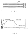
- the sample included a polycarbonate substrate having tracking grooves formed therein with a track pitch of 1.6 ⁇ m.
- a first protective layer of (ZnS) 70 (SiO 2 ) 30 was deposited in 20 nm thick approx. by sputter, in an atmosphere of argon and 20% methane, in accordance with the method described above for Example V. Recording layers of Ge 22 -Se 22 -Te 56 and Bi 2 -Te 3 deposited in 40 nm and 30 nm thick, respectively, in accordance with example V.
- a second protective layer having the same composition as the first protective layer was deposited by sputtering in approx. 20 nm thick over the recording layer.
- An ultraviolet cured resin layer of the same type as layer 114 of disc 100 (Fig. 1) was applied in several microns thick by spin coating to a thickness of several microns.
- the C/N was measured using a carrier signal frequency of 3.7 MHz and a resolution of bandwidth of 30 kHz.
- the linear velocity of the disc during recording and playback was kept at 6 m/sec, the record/playback laser wavelength was 830 nm and the objective lens with a numerical aperture of 0.55.
- Fig. 17 illustrates the C/N ratio plotted as a function of recording laser power level.
- the plot in Fig. 17 demonstrates satisfactory recording quality when a hydrocarbon polymer is included in the protective layer between the substrate and the recording layer.
- Optical discs can be constructed with an inorganic dielectric protective layer deposited over the recording layer and an organic resin layer deposited over the protective layer.
- the dielectric protective layer is provided over the recording layer to prevent corrosion of the recording layer.
- the resin layer is provided for mechanical protection of the recording layer.
- disc 100 (Fig. 1) in which inorganic protective layer 112 is deposited over recording layer 106 and resin layer 114 is deposited over layer 112.
- adhesion between the inorganic protective layer and the organic resin layer is greatly improved by interposing therebetween an organic plasma polymer film.
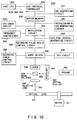
- Fig. 18 illustrates a sectional view of an optical disc 500 constructed in accordance with an embodiment of the present invention to include an organic plasma polymer film.
- Disc 500 includes a substrate 502 composed of a plastic material such as acrylic or polycarbonate.
- a first inorganic dielectric protective layer 504 is deposited on substrate 502.
- a recording layer 506 is deposited on layer 504 and consists of two sublayers 508 and 510.
- Sublayer 508 can be deposited in the same manner as layer 108 of disc 100 (Fig. 1), e.g., by sputtering Ge 22 Sb 22 Te 56 to a thickness of approximately 40 nm.
- Sublayer 510 can be deposited by sputtering in the same manner as layer 110 of disc 100, e.g., Bi 2 Te 3 deposited to a thickness of approximately 30 nm. Recording layer 506 is so constructed to enable recording on disc 500 in the alloying mode.
- a second inorganic dielectric protective layer 512 is deposited over recording layer 506.
- Protective layers 504 and 512 can each be provided as consisting of SiO 2 , ZnS, SiN, Al 2 O 3 or one of the above described mixtures of these materials.
- Each of layers 504 and 512 is deposited by sputtering in a manner and to a thickness as previously described herein.
- Disc 500 also includes an organic plasma polymer layer 514 on protective layer 512.
- Layer 514 is formed in the same sputtering system used for depositing layers 504-512, by introducing a hydrocarbon gas to which capacitively coupled RF power is applied across plate electrodes such a deposition technique being known in the art as an easy method for plasma polymer formation. Alternatively, the hydrocarbon gas can be introudced to which inductively coupled RF power is also applied.
- Suitable hydrocarbon gases for formation of plasma polymer layer 514 include methane, ethane, propane, or butane.
- a plasma polymer layer can also be formed with components of carbon, hydrogen and nitrogen by mixing N 2 and/or NH 3 with methane gas.
- Layer 514 is formed to a thickness of approximately 5 nm to 100 nm and preferably 30 nm to 100 nm.
- a resin layer 516 is deposited over plasma polymer layer 514.
- Layer 516 can have the same composition and thickness and can be deposited by the same method as described for the deposition of layer 114 of optical disc 100 (Fig. 1).
- Layer 516 has a satisfactory adhesive bond to layer 514.
- the present inventors believe this satisfactory bond may be achieved because both materials are organic.
- Plasma polymer layer 514 also forms a satisfactory adhesive bond with inorganic protective layer 512. It is believed that the plasma deposition technique employed to deposit layer 514 causes a molecular reaction, promoting molecular bonding, between the fragments produced by the plasma and inorganic layer 512. As a result, plasma polymer layer 514 forms a stronger bond with layer 512 than would the resin layer if it were instead directly deposited on layer 512 by spin coating. (Note: fragments mean some kinds of decomposition products of starting gas molecule such as CH 3 , CH 2 , CH and H.
- a plasma polymer film was deposited on an inorganic layer composed of ZnS and SiO 2 .
- the deposition was carried out in a vacuum state less than 1 ⁇ 10 -5 Torr into which methane gas was introduced at 20 sccm while a pressure of 0.01 Torr was maintained.
- Capacitively coupled RF source of 70W was utilized for the deposition of the plasma polymer film.
- An optical disc according to the present invention has been described as including a recording layer having sublayers of Ge-Sb-Te and Bi-Te.
- a first inorganic dielectric protective layer is preferably provided between the substrate and recording layer.
- a second inorganic dielectric protective layer can also be provided over the recording layer. While each of these protective layers is preferably provided as a mixture in the range from (ZnS) 80 (SiO 2 ) 20 to (ZnS) 20 (SiO 2 ) 80 , the invention can be successfully practiced with either or both of the protective layers composed of mixtures in the ranges (ZnS) 80 (SiN) 20 to (ZnS) 20 (SiN) 80 and (ZnS) 80 (Al 2 O 3 ) 20 to (ZnS) 20 (Al 2 O 3 ) 80 , as well as being composed of any one of SiO 2 , ZnS, SiN and Al 2 O 3 .
- the alloying mode disc construction according to the present invention can be provided without provision of at least the first protective layer.
- alloying mode disc constructed according to the present invention can also advantageously include the features described above for overcoming structural problems experienced with conventional optical discs.
- the aging technique broadly set forth herein is effective for adapting other optical disc structures for use in anticipated operating environments, including discs having a single substrate and two-sided discs which do not include a central reinforcing plate.
- Recording apparatus 300 has been described with respect to enabling recording with a single apparatus on alloying and phase transformation mode type discs.
- all types of optical media can be constructed to have associated therewith, specific information about the type of disc and any other parameters relevant to the means by which a recording laser beam can be most effectively controlled to optimize recording on such media.
Claims (8)
- Optisches Aufzeichnungsmedium zum Aufzeichnen von Informationen, mit einem Substrat;dadurch gekennzeichnet, daßeiner Aufzeichnungsschicht, die eine erste Teilschicht, die auf einem vorbestimmten Abschnitt des Substrats angeordnet ist, und eine zweite Teilschicht umfaßt, die auf der ersten Teilschicht angeordnet ist,wobei die erste und die zweite Teilschicht zumindest teilweise in eine einzige Legierungsschicht umgewandelt werden können, wenn sie durch einen Laserstrahl bestrahlt werden, und Informationen durch diese mindestens teilweise Umwandlung aufgezeichnet werden können,die erste Teilschicht im wesentlichen aus einer Mischung aus Ge, Sb und Te besteht, und die zweite Teilschicht im wesentlichen aus einer Mischung aus Bi und Te besteht.
- Optisches Aufzeichnungsmedium nach Anspruch 1, bei dem die erste Teilschicht eine Dicke im Bereich von 30 nm bis 60 nm aufweist, und die zweite Teilschicht eine Dicke im Bereich von 20 nm bis 50 nm besitzt.
- Optisches Aufzeichnungsmedium nach Anspruch 1 oder 2, bei dem die erste Teilschicht eine Zusammensetzung aufweist, die sich auf einer Linie befindet, die Sb2Te3 und GeTe in einem ternären Ge-Sb-Te-Zusammensetzungsdiagramm verbindet.
- Optisches Aufzeichnungsmedium nach Anspruch 1, 2 oder 3, bei dem die zweite Teilschicht eine Zusammensetzung aus Bi2Te3 aufweist.
- Optisches Aufzeichnungsmedium nach einem der vorhergehenden Ansprüche, bei dem das Substrat aus einem organischen Material besteht, und bei dem das Aufzeichungsmedium weiterhin eine anorganische Schutzschicht zwischen der Aufzeichnungsschicht und dem Substrat enthält.
- Optisches Aufzeichnungsmedium nach Anspruch 5. bei dem die Schutzschicht im wesentlichen aus einem Material besteht, das aus einer Gruppe ausgewählt ist, die aus einer Mischung in dem Bereich von (ZnS)80(SiO2)20 bis (ZnS)20(SiO2)80; einer Mischung in dem Bereich von (ZnS)80(SiN)20 bis (ZnS)20(SiN)80; und einer Mischung in dem Bereich von (ZnS)80(Al2O3)20 bis (Zns)20(Al2O3)80 besteht.
- Optisches Aufzeichnungsmedium nach einem der Ansprüche 1 bis 4, bei dem das Substrat aus einem organischen Material besteht undbei dem das Aufzeichnungsmedium weiterhin enthält:eine erste anorganische Schutzschicht zwischen der Aufzeichnungsschicht und dem Substrat, undeine zweite anorganische Schutzschicht, die auf der Aufzeichnungsschicht angeordnet ist.
- Optisches Aufzeichnungsmedium nach Anspruch 7, bei dem sowohl die erste als auch die zweite Schutzschicht jeweils im wesentlichen aus einem Material bestehen, das aus einer Gruppe ausgewählt ist, die aus einer Mischung im Bereich von (ZnS)80(SiO2)20 bis (ZnS)20(SiO2)80, einer Mischung im Bereich von (ZnS)80(SiN)20 bis (ZnS)20(SiN)80, und einer Mischung im Bereich von (ZnS)80(Al2O3)20 bis (ZnS)20(Al2O3)80 besteht.
Applications Claiming Priority (1)
| Application Number | Priority Date | Filing Date | Title |
|---|---|---|---|
| PCT/JP1993/000782 WO1994029856A1 (en) | 1993-06-11 | 1993-06-11 | Optical recording medium and recording system |
Publications (2)
| Publication Number | Publication Date |
|---|---|
| EP0708962A1 EP0708962A1 (de) | 1996-05-01 |
| EP0708962B1 true EP0708962B1 (de) | 1999-10-20 |
Family
ID=14070331
Family Applications (1)
| Application Number | Title | Priority Date | Filing Date |
|---|---|---|---|
| EP93913506A Expired - Lifetime EP0708962B1 (de) | 1993-06-11 | 1993-06-11 | Optiches aufzeichnungsmedium und speichersystem |
Country Status (5)
| Country | Link |
|---|---|
| US (1) | US5796708A (de) |
| EP (1) | EP0708962B1 (de) |
| JP (1) | JP2896231B2 (de) |
| DE (1) | DE69326846T2 (de) |
| WO (1) | WO1994029856A1 (de) |
Families Citing this family (21)
| Publication number | Priority date | Publication date | Assignee | Title |
|---|---|---|---|---|
| US5585158A (en) * | 1995-06-07 | 1996-12-17 | Eastman Kodak Company | Recordable optical element using low absorption materials |
| JPH1064120A (ja) * | 1996-08-20 | 1998-03-06 | Toshiba Corp | ランド・グルーブ記録用情報記録媒体 |
| JPH1173692A (ja) * | 1997-06-27 | 1999-03-16 | Tdk Corp | 光記録媒体およびその製造方法 |
| KR100350983B1 (ko) * | 2000-02-03 | 2002-08-28 | 삼성전자 주식회사 | 레이저 다이오드 드라이버, 이에 적합한 광기록/재생기기의 초기화 방법, 그리고 레이저 다이오드 드라이버의구동 방법 |
| JP4374698B2 (ja) * | 2000-02-25 | 2009-12-02 | ソニー株式会社 | 記録装置 |
| JP2002092956A (ja) * | 2000-09-13 | 2002-03-29 | Nec Corp | 光学情報記録媒体およびその製造方法 |
| US6753059B2 (en) * | 2001-03-29 | 2004-06-22 | Korea Institute Of Science And Technology | Optical recording material and optical recording medium using same |
| JP2003059124A (ja) * | 2001-08-10 | 2003-02-28 | Tdk Corp | 光ディスクの製造方法 |
| US7554898B2 (en) * | 2002-02-26 | 2009-06-30 | Dphi Acquisitions, Inc. | Dual density disc with associated properties |
| CN100583256C (zh) * | 2002-12-19 | 2010-01-20 | 皇家飞利浦电子股份有限公司 | 光信息存储介质、装置及制造方法 |
| KR100694047B1 (ko) * | 2004-05-17 | 2007-03-12 | 삼성전자주식회사 | 정보저장매체 및 정보기록재생장치 |
| WO2006009107A1 (ja) * | 2004-07-16 | 2006-01-26 | Mitsubishi Kagaku Media Co., Ltd. | 光記録媒体及び光記録媒体の光記録方法 |
| US7265063B2 (en) * | 2004-10-22 | 2007-09-04 | Hewlett-Packard Development Company, L.P. | Method of forming a component having dielectric sub-layers |
| US20070003731A1 (en) * | 2005-06-29 | 2007-01-04 | Micron Technology, Inc. | Gold-semiconductor phase change memory for archival data storage |
| US20070092681A1 (en) * | 2005-10-20 | 2007-04-26 | Shuy Geoffrey W | Generating optical contrast using thin layers |
| US20080056089A2 (en) * | 2005-10-20 | 2008-03-06 | Lanyo Technology Co., Ltd. | Generating Optical Contrast Using Thin Layers |
| US20080056088A2 (en) * | 2005-10-20 | 2008-03-06 | Lanyo Technology Co., Ltd. | Multiple Recording Structures for Optical Recording |
| US20080057257A2 (en) * | 2005-10-20 | 2008-03-06 | Lanyo Technology Co., Ltd. | Contrast Enhancement for Optical Recording |
| US20080057256A2 (en) * | 2005-10-20 | 2008-03-06 | Lanyo Technology Co., Ltd. | Micro-Resonant Structure for Optical Recording |
| CN102171759B (zh) * | 2008-09-12 | 2017-01-18 | 布莱阿姆青年大学 | 包含碳及金属层的数据存储媒介 |
| EP2187393A1 (de) * | 2008-11-13 | 2010-05-19 | Thomson Licensing | Optisches Aufzeichnungsmedium mit einmal- und wiederbeschreibbaren Eigenschaften |
Family Cites Families (24)
| Publication number | Priority date | Publication date | Assignee | Title |
|---|---|---|---|---|
| US5003526A (en) * | 1980-07-16 | 1991-03-26 | Discovision Associates | System for recording digital information in a pulse-length modulation format |
| US4477819A (en) * | 1982-06-14 | 1984-10-16 | International Business Machines Corporation | Optical recording medium |
| JPS6028045A (ja) * | 1983-07-25 | 1985-02-13 | Sony Corp | 情報記録媒体 |
| JPS60160036A (ja) * | 1984-01-28 | 1985-08-21 | Toshiba Corp | 光デイスク |
| FR2575857B1 (fr) * | 1984-11-29 | 1995-03-03 | Canon Kk | Appareil de stockage optique d'informations |
| CA1236693A (en) * | 1985-02-22 | 1988-05-17 | Isao Morimoto | Information recording medium |
| JPS61280051A (ja) * | 1985-06-04 | 1986-12-10 | Daicel Chem Ind Ltd | 貼り合わせ光デイスクの製法 |
| JPH0695388B2 (ja) * | 1985-06-14 | 1994-11-24 | 株式会社東芝 | 情報記録媒体 |
| US4737408A (en) * | 1985-08-21 | 1988-04-12 | Tdk Corporation | Magneto-optical recording medium having plasma-polymerized protective layers |
| US4847132A (en) * | 1986-10-20 | 1989-07-11 | Matsushita Electric Industrial Co., Ltd. | Protective layer for optical information recording medium |
| JPS63146250A (ja) * | 1986-12-09 | 1988-06-18 | Daicel Chem Ind Ltd | 光デイスクの貼り合わせ方法 |
| JPS63187430A (ja) * | 1987-01-30 | 1988-08-03 | Toshiba Corp | 情報記録媒体 |
| JPH01251349A (ja) * | 1988-03-30 | 1989-10-06 | Nec Home Electron Ltd | 光磁気記録媒体 |
| EP0337445A3 (de) * | 1988-04-13 | 1991-01-16 | Hitachi, Ltd. | Laminare Struktur bestehend aus einem organischen Material und aus einem anorganischen Material, Methoden zu ihrer Herstellung und ihrer Benutzung |
| JP2573301B2 (ja) * | 1988-04-22 | 1997-01-22 | 株式会社東芝 | ディスク装置 |
| JP2680039B2 (ja) * | 1988-06-08 | 1997-11-19 | 株式会社日立製作所 | 光情報記録再生方法及び記録再生装置 |
| EP0376700B1 (de) * | 1988-12-28 | 1995-02-22 | Matsushita Electric Industrial Co., Ltd. | Medium für Datenspeicherung |
| JP2773898B2 (ja) * | 1989-05-23 | 1998-07-09 | オリンパス光学工業株式会社 | 光学式情報記録/再生装置 |
| JPH03116539A (ja) * | 1989-09-29 | 1991-05-17 | Toshiba Corp | ディスク装置 |
| US5096742A (en) * | 1990-01-09 | 1992-03-17 | Hoechst Celanese Corporation | High temperature, high humidity stabilization process for optical information storage media containing polycarbonate substrates |
| JP2809835B2 (ja) * | 1990-07-30 | 1998-10-15 | 松下電器産業株式会社 | 光ディスク装置および光ディスク |
| JPH04186537A (ja) * | 1990-11-21 | 1992-07-03 | Hitachi Ltd | 情報記録用部材 |
| EP0541376B1 (de) * | 1991-11-07 | 1998-06-03 | Toray Industries, Inc. | Optisches Aufzeichnungsmedium |
| TR200101726T2 (tr) * | 1998-12-17 | 2001-12-21 | Pirelli Pneumatici S.P.A. | Taşıt tekerlekleri için bir lastiğin bileşenlerinin üretilmesi için bir yöntem ve bir düzenek. |
-
1993
- 1993-06-11 US US08/556,992 patent/US5796708A/en not_active Expired - Lifetime
- 1993-06-11 DE DE69326846T patent/DE69326846T2/de not_active Expired - Lifetime
- 1993-06-11 EP EP93913506A patent/EP0708962B1/de not_active Expired - Lifetime
- 1993-06-11 WO PCT/JP1993/000782 patent/WO1994029856A1/en active IP Right Grant
- 1993-06-11 JP JP7501553A patent/JP2896231B2/ja not_active Expired - Fee Related
Also Published As
| Publication number | Publication date |
|---|---|
| JP2896231B2 (ja) | 1999-05-31 |
| DE69326846D1 (de) | 1999-11-25 |
| US5796708A (en) | 1998-08-18 |
| JPH08508843A (ja) | 1996-09-17 |
| DE69326846T2 (de) | 2000-06-15 |
| WO1994029856A1 (en) | 1994-12-22 |
| EP0708962A1 (de) | 1996-05-01 |
Similar Documents
| Publication | Publication Date | Title |
|---|---|---|
| EP0708962B1 (de) | Optiches aufzeichnungsmedium und speichersystem | |
| EP0978831B1 (de) | Optisches Aufzeichnungsmedium und Verfahren zu seiner Herstellung, Verfahren zur Informationsaufzeichnung und -wiedergabe darauf, und Aufzeichnungs-/Wiedergabegerät | |
| US6071588A (en) | Optical recording medium | |
| US5862121A (en) | Double-layered information recording medium having information recording layers | |
| EP0644537A2 (de) | Informationsaufzeichnungsmedium | |
| US7291375B2 (en) | Phase-change optical recording medium | |
| KR100709931B1 (ko) | 정보 기록 매체 및 그 제조 방법 | |
| EP1118988B1 (de) | Optisches informationsaufzeichnungsmedium und verfahren zur initialisierung desselben | |
| US20060083150A1 (en) | Optical information recording medium and method for manufacturing same | |
| US5151295A (en) | Process for manufacturing an optical recording medium | |
| US6607869B1 (en) | Optical information recording medium and method of manufacturing the same | |
| AU601117B2 (en) | Optical recording medium and method of its production | |
| US7304930B2 (en) | Optical information recording medium and recording method using the same | |
| US4879205A (en) | Information storage medium and a method of manufacturing the same | |
| EP0307750B1 (de) | Gebrauch eines Speichermediums in einem Verfahren zur Aufnahme von Informationen | |
| WO2007043210A9 (en) | Power determining method, single-sided multilayer optical disk, recording method, computer program product, computer-readable medium, and optical disk apparatus | |
| WO2004105008A1 (ja) | 光学的情報記録媒体及びその製造方法 | |
| WO2004070717A1 (ja) | 光記録媒体およびその製造方法 | |
| EP1695839A1 (de) | Optisches aufzeichnungsmedium und herstellungsverfahren dafür, sputter-target, verwendung des optischen aufzeichnungsmediums und optische aufzeichnungs-/reproduktionsvorrichtung | |
| JPH08267925A (ja) | 光記録媒体およびその製造方法 | |
| US6893543B1 (en) | Information carrier and method for producing the same | |
| JP2562427B2 (ja) | 光情報記録媒体 | |
| JPH09115180A (ja) | 光記録媒体 | |
| JPH0757298A (ja) | 光記録媒体とその製造方法 | |
| JP2001143326A (ja) | 光学的情報記録用媒体 |
Legal Events
| Date | Code | Title | Description |
|---|---|---|---|
| PUAI | Public reference made under article 153(3) epc to a published international application that has entered the european phase |
Free format text: ORIGINAL CODE: 0009012 |
|
| 17P | Request for examination filed |
Effective date: 19951206 |
|
| AK | Designated contracting states |
Kind code of ref document: A1 Designated state(s): DE FR GB NL |
|
| 17Q | First examination report despatched |
Effective date: 19961125 |
|
| GRAG | Despatch of communication of intention to grant |
Free format text: ORIGINAL CODE: EPIDOS AGRA |
|
| GRAG | Despatch of communication of intention to grant |
Free format text: ORIGINAL CODE: EPIDOS AGRA |
|
| GRAH | Despatch of communication of intention to grant a patent |
Free format text: ORIGINAL CODE: EPIDOS IGRA |
|
| GRAH | Despatch of communication of intention to grant a patent |
Free format text: ORIGINAL CODE: EPIDOS IGRA |
|
| GRAA | (expected) grant |
Free format text: ORIGINAL CODE: 0009210 |
|
| AK | Designated contracting states |
Kind code of ref document: B1 Designated state(s): DE FR GB NL |
|
| REF | Corresponds to: |
Ref document number: 69326846 Country of ref document: DE Date of ref document: 19991125 |
|
| ET | Fr: translation filed | ||
| PLBE | No opposition filed within time limit |
Free format text: ORIGINAL CODE: 0009261 |
|
| STAA | Information on the status of an ep patent application or granted ep patent |
Free format text: STATUS: NO OPPOSITION FILED WITHIN TIME LIMIT |
|
| 26N | No opposition filed | ||
| REG | Reference to a national code |
Ref country code: GB Ref legal event code: IF02 |
|
| PGFP | Annual fee paid to national office [announced via postgrant information from national office to epo] |
Ref country code: FR Payment date: 20110621 Year of fee payment: 19 |
|
| PGFP | Annual fee paid to national office [announced via postgrant information from national office to epo] |
Ref country code: NL Payment date: 20110621 Year of fee payment: 19 Ref country code: GB Payment date: 20110608 Year of fee payment: 19 |
|
| PGFP | Annual fee paid to national office [announced via postgrant information from national office to epo] |
Ref country code: DE Payment date: 20110608 Year of fee payment: 19 |
|
| REG | Reference to a national code |
Ref country code: NL Ref legal event code: V1 Effective date: 20130101 |
|
| GBPC | Gb: european patent ceased through non-payment of renewal fee |
Effective date: 20120611 |
|
| REG | Reference to a national code |
Ref country code: FR Ref legal event code: ST Effective date: 20130228 |
|
| REG | Reference to a national code |
Ref country code: DE Ref legal event code: R119 Ref document number: 69326846 Country of ref document: DE Effective date: 20130101 |
|
| PG25 | Lapsed in a contracting state [announced via postgrant information from national office to epo] |
Ref country code: NL Free format text: LAPSE BECAUSE OF NON-PAYMENT OF DUE FEES Effective date: 20130101 Ref country code: GB Free format text: LAPSE BECAUSE OF NON-PAYMENT OF DUE FEES Effective date: 20120611 Ref country code: DE Free format text: LAPSE BECAUSE OF NON-PAYMENT OF DUE FEES Effective date: 20130101 Ref country code: FR Free format text: LAPSE BECAUSE OF NON-PAYMENT OF DUE FEES Effective date: 20120702 |