EP0705489B1 - Vorrichtung zum anschliessen eines koaxialkabels an mit weiterführenden leitungseinrichtungen verbindbare kontakte - Google Patents
Vorrichtung zum anschliessen eines koaxialkabels an mit weiterführenden leitungseinrichtungen verbindbare kontakte Download PDFInfo
- Publication number
- EP0705489B1 EP0705489B1 EP94913107A EP94913107A EP0705489B1 EP 0705489 B1 EP0705489 B1 EP 0705489B1 EP 94913107 A EP94913107 A EP 94913107A EP 94913107 A EP94913107 A EP 94913107A EP 0705489 B1 EP0705489 B1 EP 0705489B1
- Authority
- EP
- European Patent Office
- Prior art keywords
- contact
- insert
- casing
- coaxial cable
- cavity
- Prior art date
- Legal status (The legal status is an assumption and is not a legal conclusion. Google has not performed a legal analysis and makes no representation as to the accuracy of the status listed.)
- Expired - Lifetime
Links
Images
Classifications
-
- H—ELECTRICITY
- H01—ELECTRIC ELEMENTS
- H01R—ELECTRICALLY-CONDUCTIVE CONNECTIONS; STRUCTURAL ASSOCIATIONS OF A PLURALITY OF MUTUALLY-INSULATED ELECTRICAL CONNECTING ELEMENTS; COUPLING DEVICES; CURRENT COLLECTORS
- H01R9/00—Structural associations of a plurality of mutually-insulated electrical connecting elements, e.g. terminal strips or terminal blocks; Terminals or binding posts mounted upon a base or in a case; Bases therefor
- H01R9/03—Connectors arranged to contact a plurality of the conductors of a multiconductor cable, e.g. tapping connections
- H01R9/05—Connectors arranged to contact a plurality of the conductors of a multiconductor cable, e.g. tapping connections for coaxial cables
- H01R9/0521—Connection to outer conductor by action of a nut
-
- H—ELECTRICITY
- H01—ELECTRIC ELEMENTS
- H01R—ELECTRICALLY-CONDUCTIVE CONNECTIONS; STRUCTURAL ASSOCIATIONS OF A PLURALITY OF MUTUALLY-INSULATED ELECTRICAL CONNECTING ELEMENTS; COUPLING DEVICES; CURRENT COLLECTORS
- H01R4/00—Electrically-conductive connections between two or more conductive members in direct contact, i.e. touching one another; Means for effecting or maintaining such contact; Electrically-conductive connections having two or more spaced connecting locations for conductors and using contact members penetrating insulation
- H01R4/28—Clamped connections, spring connections
- H01R4/50—Clamped connections, spring connections utilising a cam, wedge, cone or ball also combined with a screw
- H01R4/5033—Clamped connections, spring connections utilising a cam, wedge, cone or ball also combined with a screw using wedge or pin penetrating into the end of a wire in axial direction of the wire
-
- H—ELECTRICITY
- H01—ELECTRIC ELEMENTS
- H01R—ELECTRICALLY-CONDUCTIVE CONNECTIONS; STRUCTURAL ASSOCIATIONS OF A PLURALITY OF MUTUALLY-INSULATED ELECTRICAL CONNECTING ELEMENTS; COUPLING DEVICES; CURRENT COLLECTORS
- H01R9/00—Structural associations of a plurality of mutually-insulated electrical connecting elements, e.g. terminal strips or terminal blocks; Terminals or binding posts mounted upon a base or in a case; Bases therefor
- H01R9/03—Connectors arranged to contact a plurality of the conductors of a multiconductor cable, e.g. tapping connections
- H01R9/05—Connectors arranged to contact a plurality of the conductors of a multiconductor cable, e.g. tapping connections for coaxial cables
- H01R9/053—Connectors arranged to contact a plurality of the conductors of a multiconductor cable, e.g. tapping connections for coaxial cables using contact members penetrating insulation
Definitions
- the invention relates to a device according to the Preamble of claim 1.
- the first contact has the shape of a thin-walled sleeve corresponding to the diameter of the inner conductor of the coaxial cable Inside diameter
- the second contact has the shape a thin-walled hollow cylinder coaxial with the first contact with the diameter of the insulation between the inner conductor and cable shield of the coaxial cable corresponding inner diameter.
- the hollow cylinder runs on the one facing the coaxial cable Pointed out and protrudes over the first, inner Contact out to the coaxial cable.
- the coaxial cable in the Housing of the device with the exposed inner insulation threaded into the second contact and pushed forward, the first contact being along the inner conductor between pushes this and the insulation and an end section of takes this in contact while the second contact as before the hollow cylinder of the tool Contact with the cable shield between these and the Insulation surrounding the inner cable pushes.
- connection of the coaxial cable requires in the known Device requires a lot of work and is only with with a special tool.
- a connecting element is known in which the outer contact braid of the coaxial cable by means of indenting tongues is contacted when screwing a union nut through the cable insulation to penetrate to the field.
- the invention has for its object a device according to the preamble of the main claim to create with a reliable one at a much lower workload Simply connect one at its free end straight and vertical coaxial cable cut to the longitudinal axis without special tools and without additional than simply cutting off necessary manipulations on the cable as such.
- this will be at its end by means of a string cutter or the like, simply with a smooth clean cut surface provided coaxial cable in the Inner bore of the loose in the housing and from the clamping nut captive so far until the needle tip is a little bit into the preferably pierced multi-core inner conductor.
- the clamping nut tightened, causing the use of the contact needle underneath Taking the coaxial cable closer and closer with it Pressure area the contact tongues of the second contact to the plane bends back from its circumferential clamping. This Bending back has the effect that the tongue ends to Move the contact needle closer to each other, the outer insulation layer cut the coaxial cable and against the cable shield pressed with reliable contact with this become.
- the contact needle is still in stabbed the inner conductor.
- the subclaims relate to preferred embodiments of the Device according to protection claim 1.
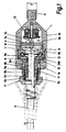
- the device according to FIG. 1 consists largely of simple rotationally symmetrical parts. It shows one two screwable parts 1a, 1b existing housing 1 on, which surrounds a coaxial to a longitudinal axis 2 cavity 3.
- the Insulating washer 4 has a central first contact in the form one of them perpendicular to the coaxial cable 6 to be connected protruding contact needle 7 with which the inner conductor 6a of the Coaxial cable 6 is connected.
- the contact needle 7 has one wide foot 7a with which it is not closer to one shown central coating consisting of solderable material the insulating washer 4 is soldered (7b). This kind the connection with the insulating washer 4 enables in particular simple alignment of the necessary alignment Edge contact needle 7, in particular the needle tip, on the axis 2.
- a second coaxial ring shoulder 3b forms, on which the second with the coaxial cable 6 contact to be connected.
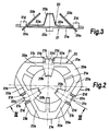
- This contact forms the in 2 and 3 contact spring device shown on a larger scale 10th
- the contact spring device 10 shown in FIGS. 2 and 3 consists of two parts, a contact element 20 and one Support element 21. These two parts lie one above the other, whereby, 1, the contact element 20 the Coaxial cable 6 is turned and the support member 21 itself between the contact element 20 and the second ring shoulder 3b forming spacer 9 is located.
- the contact element 20 is the actual contacting part to the coaxial cable 6 or its shield and points circumferentially one essentially the line of an equilateral Triangular following, with rounded corners as well as a resilient metal surrounding section 20a, of which in the middle of each straight parts acting as torsion springs formed in one piece Protruding contact tongues 20b to the center.
- These tongues 20b are outward from the straight parts extended to form tabs 20c and 6 bent obliquely out of the plane of the encircling section 20a, with their free ends forming their cutting edges reach up to the coaxial cable 6.
- the tabs 20c extend as best seen in Fig. 2, in the Alignment of the contact tongues 20b to the other side of the enclosing section 20a.
- the support element 21 has essentially the shape of a to a center hole 21a full-area triangle with rounded, with the round corners 20e of the surrounding portion 20a of the Contact element 20 congruent corners 21e.
- each straight edge 21b is pocket-like Recess 21c, which is formed in that on each side this recess two tabs 21d made of the material of the support element 21 bent up to the contact element 20 located above have been.
- the contact element 20 engages with the Tabs 20c into the pockets 21c of the support element 21 and is thus fixed in position in relation to the latter.
- the contact spring device 10 with its circumferential, the rounded corners of the triangles forming sections 20e, 21e by means of a housing part 1a supporting metallic pressure ring 12 to the second ring shoulder 3b pressed and thereby securely in the housing 1 captured.
- the contact tongues are 20b of the contact spring device 10 towards the coaxial cable 6 from the plane of the circumferential sections 20a among themselves bent out at the same angle and have one mutual distance that is only slightly larger than the outside diameter of the coaxial cable 6.
- the spring device facing away from the contact needle 7 10 is displaceable in the axial direction of the housing 1 inserted to the central axis 2 coaxial insert 11, the consists of a rubber-elastic material and with a Dimensions of the coaxial cable 6 corresponding cylindrical Center bore 11a and a truncated cone, extending from the Spring device 10 provided tapering lateral surface 11b is.
- This insert 11 points to the contact spring device 10 facing end face a fixed pressure surface 11c on the against the free ends of the contact tongues 20b of the Presses contact element 20 and tries to bend it inwards, if the insert 11 towards the metallic contact needle 7 is advanced.
- the latter is done using the Clamping nut 5, which is screwed into the housing part 1b and by means of a rigid insert 5a against the rubber elastic Insert 11 presses.
- the rigid insert 5a is cylindrical on the outside and designed inside so that it has a frustoconical surface 5c of a shape matching the conicity of the insert 11.
- Fig. 1 shows the parts of the device in the state immediately before tightening the tension nut 5.
- the coaxial cable 6 is a piece through the bore 11a in the insert 11 been pushed onto the tip of the contact needle 7, the thereby with the inner conductor of the simply smooth cut Coaxial cable 6 has come into contact. If now the clamping nut 5 is tightened, the insert 11 becomes for the viewer 1 shifted to the right and bends the contact tongues 20b by means of the pressure surface 11c towards the contact needle 7, see above that the contact tongues 20b also shifted inwards to the axis 2 and their cutting the outer insulation 6b of the coaxial cable Cut 6 and with the cable shield underneath get in touch. At the same time, the coaxial cable 6 with its inner conductor 6a a little further on the contact needle 7 postponed. In addition, the inner bore 11a of the rubber-like insert 11 tapers and the cable 6 flat captured and sealed.
- the pressure ring 12 has a frustoconical inner surface that tapers from the insert 11 towards the contact needle 7.
- the diameter of the tapered insert 11 corresponds to this Bore the diameter of the face of the insert 11 so that it can enter the bore, on the other Paths but squeezed together in the pressure ring 12 becomes and with the exercise of a sealing effect Coaxial cable 6 and the coaxial cable clamped towards the pressure ring 12 and holds in the device.
- Between the housing parts 1a and 1b is a seal between these O-ring 8 inserted.
- the cavity 3 in the housing 1 is thus after Establishing the connection of the coaxial cable 6 with the contact spring device 10 and the contact needle 7 hermetically against sealed the outside space.
- Fig. 1 In the embodiment shown in Fig. 1 is in the housing part 1b beyond the insulating plate 4, an electronic Circuit arrangement in the form of a vibration sensor 13. This is on the one hand via a line 14 with the Contact needle 7 and the other via the housing 1 with the Contact spring device 10 and thus with the inner conductor and the cable shield of the coaxial cable 6 connected.
- Deviating from the aforementioned version with built-in Electronics could also mirror the device one parallel to the insulating plate 4, for the viewer 1 to the right of the plate located level his.
- two coaxial cables could be used on simple Be connected to each other, the device as Cable coupling act.
- Another possibility is e.g. inside the housing 1 a two-wire line of a different type than that of the coaxial cable 6 to devices located outside the housing 1 lead, so use the device as an adapter.
- the housing part 1b runs in an external threaded pin that allows the device easy to attach to a machine housing which is only equipped with a threaded hole for this needs to be.
Landscapes
- Coupling Device And Connection With Printed Circuit (AREA)
- Multi-Conductor Connections (AREA)
- Connections By Means Of Piercing Elements, Nuts, Or Screws (AREA)
Description
- Fig. 1
- im zentralen Längsschnitt eine bevorzugte Ausführungsform der Vorrichtung im Zustand unmittelbar vor dem Verspannen des Einsatzes, in den das anzuschließende Koaxialkabel bereits bis auf die Kontaktnadelspitze eingeschoben worden ist,
- Fig. 2
- eine bevorzugte Ausführung der Federeinrichtung in vergrößertem Maßstab in Draufsicht, und
- Fig. 3
- die Federeinrichtung gemäß Fig. 2 im Schnitt entlang der Schnittlinie III-III in Fig. 2.
Claims (10)
- Vorrichtung zum Anschließen eines Koaxialkabels (6) an zwei mit weiterführenden Leitungseinrichtungen (14) verbindbare, in einem Gehäuse (1) befestigte, gegeneinander isolierte Kontakte (7, 10), von denen der erste Kontakt als im Gehäuse (1) starr befestigte Kontaktnadel (7) ausgeführt ist und zum axialen Einstechen in den Innenleiter (6a) des Koaxialkabels (6) stiftartig zentral in einen Hohlraum (3) des Gehäuses (1) hineinragt und der zweite Kontakt (10) den ersten Kontakt (7) in dem Hohlraum (3) koaxial umgibt, wobei das Gehäuse (1) mit einem Einsatz (11) versehen ist, der eine das Koaxialkabel (6) paßrecht aufnehmende Innenbohrung (11a) mit sich fluchtrecht zum ersten Kontakt (7) erstreckender Mittelachse (2) aufweist und mittels einer bezüglich des Gehäuses (1) verschraubbaren Spannmutter (5) in Längsrichtung der Innenbohrung (11a) verschiebbar und zwischen Spannmutter (5) und Gehäuse (1) unter Festlegung des Koaxialkabels (6) gegenüber dem letzteren verspannbar ist, dadurch gekennzeichnet, daßa) der zweite Kontakt aus einer umfangsseitig im wesentlichen starr im Gehäuse (1) eingespannten Kontaktfedereinrichtung (10) mit zur Kontaktnadel (7) hin einwärts vorragenden, am freien Ende scharfen Zungen (20b) besteht, die aus der Ebene der umfangsseitigen Einspannung unter einem untereinander gleichen Winkel schräg zur Innenbohrung (11a) des Einsatzes (11) hin herausgebogen sind, undb) der Einsatz (11) auf der der Kontaktnadel (7) und der Kontaktfedereinrichtung (10) zugewendeten Seite mit einer im wesentlichen bis an die Innenbohrung heranreichenden, zur Druckausübung auf die Zungen (20b) bestimmten starren Druckfläche (11c) versehen ist,c) wobei die Kontaktfedereinrichtung (10), die Kontaktnadel (7) und der Einsatz (11) so aufeinander abgestimmt und in dem Gehäuse (1) in Bezug aufeinander angeordnet sind, daß beim Eindringen der Kontaktnadel (7) in den Innenleiter (6a) des Koaxialkabels (6) die Zungen (20b) der Kontaktfedereinrichtung (10) die äußere Kabelisolierung (6b) durchdringen und in Kontakt mit dem darunter befindlichen Kabelschirm gepreßt werden, wenn ein im wesentlichen glatt senkrecht zu seiner Längsachse abgeschnittenes Koaxialkabel (6) in der Innenbohrung (11a) des Einsatzes (11) ein Stück auf die Kontaktnadel (7) vorgeschoben worden ist und danach der Einsatz (11) mittels der Spannmutter (5) über eine vorbestimmte Strecke zur Kontaktnadel (7) hin verschoben und dabei verspannt wird undd) die Federeinrichtung (10) ein Kontaktelement (20) aufweist, das mit einem äußeren, aus einem federnden Material bestehenden, zu einem zentralen Punkt symmetrischen Umfassungsabschnitt (20a) versehen ist, der sich entlang eines regelmäßigen Vielecks erstreckt und an den Ecken des Vielecks mindestens indirekt gegen die Wandung des Gehäusehohlraums (3) verspannbar ist, und daß sich von dem - als Torsionsfedern wirkenden - Umfassungsabschnitt (20a) in der Mitte zwischen den eingespannten Ecken die Kontaktzungen (20b) in Richtung zum zentralen Punkt einwärts erstrecken.
- Vorrichtung nach Anspruch 1, dadurch gekennzeichnet, daß der Einsatz (11) aus einem gummielastischen Material besteht.
- Vorrichtung nach Anspruch 1 oder 2, dadurch gekennzeichnet, daß die Kontaktnadel (7) senkrecht von einer harten Isolierstoffscheibe (4) vorragt, die auf einer ersten Ringschulter (3a) im Gehäusehohlraum (3) aufliegt und gegen diese verspannt ist.
- Vorrichtung nach Anspruch 3, dadurch gekennzeichnet, daß die Isolierstoffscheibe (4) eine zentrale Beschichtung aus lötbarem Material aufweist und die Kontaktnadel (7) mit einem mit der Beschichtung verlöteten Fuß (7a) versehen ist.
- Vorrichtung nach Anspruch 1, dadurch gekennzeichnet, daß die Kontaktfedereinrichtung (10) des weiteren ein Stützelement (21) aufweist, das das Kontaktelement (20) in der Mitte der geraden Teile des Umfassungsabschnitts (20a) gegen deren Verlagerung in Richtung vom Zentrum weg auswärts abstützt.
- Vorrichtung nach Anspruch 5, dadurch gekennzeichnet, daß das Kontaktelement (20) und das Stützelement (21) mit ihre relative Position festlegenden Positioniermitteln in Form von Ausnehmungen (21c) und in diese eingreifenden Lappen (20c) versehen sind.
- Vorrichtung nach einem der Ansprüche 1 bis 6, dadurch gekennzeichnet, daß die eingespannten Ecken (20e) des Kontaktelements (20) und ggf. (21e) des Stützelements (21) gegen eine zu der ersten Ringschulter (3a) parallele, von dieser im Abstand in Richtung zum freien Ende der Kontaktnadel (7) hin gelegene zweite Ringschulter (3b) im Hohlraum (3) verspannt sind.
- Vorrichtung nach einem der vorhergehenden Ansprüche, dadurch gekennzeichnet, daß der Einsatz (11) gehäuseauswärts kegelig verjüngt ist und in einen koaxialen Hohlraum (5b) in der Spannmutter (5) hineinragt, dessen Innenfläche (5c) eine Gegenfläche von gleicher Verjüngung für den an ihr anliegenden Einsatz (11) bildet.
- Vorrichtung nach Anspruch 8, dadurch gekennzeichnet, daß die verjüngte Innenfläche (5c) des koaxialen Hohlraums (5b) in der Spannmutter durch die Innenfläche eines weiteren, außen zylindrischen Einsatzes (5a) gebildet wird, der in die Spannmutter (5) paßrecht eingeschoben ist.
- Vorrichtung nach einem der vorhergehenden Ansprüche, dadurch gekennzeichnet, daß der Gehäusehohlraum (3) zum Einsatz (11) hin von einem Duchmesser, der kleiner ist als der stirnseitige Durchmesser des Einsatzes (11), auf diesen stirnseitigen Duchmesser kegelig erweitert ist.
Applications Claiming Priority (1)
| Application Number | Priority Date | Filing Date | Title |
|---|---|---|---|
| PCT/EP1994/001023 WO1995027319A1 (de) | 1994-03-31 | 1994-03-31 | Vorrichtung zum anschliessen eines koaxialkabels an mit weiterführenden leitungseinrichtungen verbindbare kontakte |
Publications (2)
| Publication Number | Publication Date |
|---|---|
| EP0705489A1 EP0705489A1 (de) | 1996-04-10 |
| EP0705489B1 true EP0705489B1 (de) | 2000-05-17 |
Family
ID=8165840
Family Applications (1)
| Application Number | Title | Priority Date | Filing Date |
|---|---|---|---|
| EP94913107A Expired - Lifetime EP0705489B1 (de) | 1994-03-31 | 1994-03-31 | Vorrichtung zum anschliessen eines koaxialkabels an mit weiterführenden leitungseinrichtungen verbindbare kontakte |
Country Status (5)
| Country | Link |
|---|---|
| US (1) | US5899769A (de) |
| EP (1) | EP0705489B1 (de) |
| JP (1) | JPH08511376A (de) |
| DE (2) | DE9405994U1 (de) |
| WO (1) | WO1995027319A1 (de) |
Families Citing this family (16)
| Publication number | Priority date | Publication date | Assignee | Title |
|---|---|---|---|---|
| US6089913A (en) * | 1996-11-12 | 2000-07-18 | Holliday; Randall A. | End connector and crimping tool for coaxial cable |
| US6376754B1 (en) * | 1997-03-07 | 2002-04-23 | Asgrow Seed Company | Plants having resistance to multiple herbicides and its use |
| US6244893B1 (en) * | 1998-10-30 | 2001-06-12 | Charles Dudley | Stranded wire electrical connector |
| DE19957518C2 (de) * | 1999-11-30 | 2002-06-20 | Thomas Hohwieler | Verfahren und Vorrichtung zum Kontaktieren eines Aussenleiters eines Koaxialkabels |
| US6830479B2 (en) * | 2002-11-20 | 2004-12-14 | Randall A. Holliday | Universal crimping connector |
| US6783394B1 (en) | 2003-03-18 | 2004-08-31 | Randall A. Holliday | Universal multi-stage compression connector |
| CN1577978B (zh) * | 2003-07-08 | 2010-11-17 | 兰德尔·A·霍利迪 | 通用压接连接器 |
| DE202004012151U1 (de) * | 2004-08-04 | 2005-12-22 | Weidmüller Interface GmbH & Co. KG | Anschluß- und Verbindungsvorrichtung |
| US8269101B2 (en) | 2009-03-30 | 2012-09-18 | John Mezzalingua Associates, Inc. | Signal device housing with integrated restricted connections |
| US7867025B2 (en) * | 2009-05-29 | 2011-01-11 | John Mezzalingua, Associates, Inc. | Cable connector with supported center conductor contact |
| DE102010025549A1 (de) * | 2010-06-29 | 2011-12-29 | Phoenix Contact Gmbh & Co. Kg | Solarsteckverbindung |
| DE102011018993A1 (de) * | 2011-04-28 | 2012-10-31 | Mc Technology Gmbh | Schirmkontaktfeder |
| BR112016015026A2 (pt) | 2013-12-24 | 2017-08-08 | Ppc Broadband Inc | Um conector que possui um engatador de condutor interno |
| BR112017001928A2 (pt) | 2014-07-30 | 2017-11-28 | Corning Optical Comm Rf Llc | ?conectores de cabo coaxial com elementos de retenção condutor? |
| CN113556419B (zh) * | 2021-09-23 | 2021-12-10 | 深圳市奇彩液晶显示技术有限公司 | 一种手机屏幕排线的本压设备 |
| DE102023107600B3 (de) | 2023-03-27 | 2024-08-22 | Christian Herner | Selbsthaltende Prüfspitze für feindrähtige Einzeladerleitungen |
Family Cites Families (9)
| Publication number | Priority date | Publication date | Assignee | Title |
|---|---|---|---|---|
| DE1921200A1 (de) * | 1969-04-25 | 1970-11-05 | Siemens Ag | Koaxiale Anschlussvorrichtung fuer Hochfrequenzkabel |
| FR2062750A5 (de) * | 1970-09-28 | 1971-06-25 | Camera Julien | |
| US3744007A (en) * | 1971-10-01 | 1973-07-03 | Vikoa Inc | Three-piece coaxial cable connector |
| DE2425070C3 (de) * | 1974-05-24 | 1980-03-06 | Wolfgang 2351 Trappenkamp Freitag | Elektrischer Steckverbinder für Koaxialkabel |
| US5068248A (en) * | 1984-04-02 | 1991-11-26 | Merck & Co., Inc. | N-alkenyl-3-hydroxybenzo[b]thiophene-2-carboxamide derivatives as dual cyclooxygenase and lipoxygenase inhibitors |
| US4761146A (en) * | 1987-04-22 | 1988-08-02 | Spm Instrument Inc. | Coaxial cable connector assembly and method for making |
| US5059747A (en) * | 1989-12-08 | 1991-10-22 | Thomas & Betts Corporation | Connector for use with metal clad cable |
| US5052946A (en) * | 1990-10-24 | 1991-10-01 | Haug Gmbh & Co. Kg | Plug connector for high-voltage coaxial cables |
| DE4140227A1 (de) * | 1991-01-11 | 1992-07-23 | Wolfgang B Thoerner | Vorrichtung fuer den anschluss eines kabelendes |
-
1994
- 1994-03-31 JP JP7525362A patent/JPH08511376A/ja active Pending
- 1994-03-31 DE DE9405994U patent/DE9405994U1/de not_active Expired - Lifetime
- 1994-03-31 DE DE59409367T patent/DE59409367D1/de not_active Expired - Fee Related
- 1994-03-31 US US08/556,928 patent/US5899769A/en not_active Expired - Fee Related
- 1994-03-31 WO PCT/EP1994/001023 patent/WO1995027319A1/de not_active Ceased
- 1994-03-31 EP EP94913107A patent/EP0705489B1/de not_active Expired - Lifetime
Also Published As
| Publication number | Publication date |
|---|---|
| DE9405994U1 (de) | 1994-07-14 |
| US5899769A (en) | 1999-05-04 |
| WO1995027319A1 (de) | 1995-10-12 |
| EP0705489A1 (de) | 1996-04-10 |
| JPH08511376A (ja) | 1996-11-26 |
| DE59409367D1 (de) | 2000-06-21 |
Similar Documents
| Publication | Publication Date | Title |
|---|---|---|
| EP0842552B1 (de) | Kabelanschlusselement | |
| DE2522499C2 (de) | Elektrischer Steckverbinder | |
| CH631579A5 (de) | Elektrische klemme zum anbringen an einer tragschiene. | |
| DE9405994U1 (de) | Vorrichtung zum Anschließen eines Koaxialkabels an mit weiterführenden Leitungseinrichtungen verbindbare Kontakte | |
| DE2938166A1 (de) | Vorrichtung zum selbstaendigen ausrichten optischer einfaserleitungen in steckverbindern | |
| DE4339914C2 (de) | Wasserdichter Steckverbinder | |
| DE3138299C2 (de) | ||
| DE2623145A1 (de) | Steckverbindung | |
| DE10255190B4 (de) | Rundsteckverbindungseinheit | |
| EP0908995A1 (de) | Kabelverschraubung für ein abgeschirmtes Kabel | |
| DE68910918T2 (de) | Ausrüstung zum Verteilen einer Flüssigkeit. | |
| DE2852886A1 (de) | Kontaktbaustein | |
| DE4210491C2 (de) | Vorrichtung zur Herstellung einer lösbaren Verbindung zwischen einer Signalleitung und einer elektrisch leitenden Anschlußbuchse in einem Bauteil eines Mittelspannungs- oder Hochspannungsenergieversorgungssystems | |
| EP0086995B1 (de) | Grundkörper insbesondere für Skibindungen | |
| EP0640786B1 (de) | Kombinierte Schlauch- und Kabelverschraubung | |
| DE2645450A1 (de) | Stecksystem fuer stereophoniekanaele | |
| DE2545179B2 (de) | Steckverbinder | |
| DE19525801C2 (de) | Vorrichtung zum elektrisch leitenden Verbinden von zwei elektrischen Leitungen | |
| DE3623857A1 (de) | Stecker fuer ein koaxialkabel | |
| DE19754527C2 (de) | Klinkenbuchse | |
| DE1640633B1 (de) | Elektrische Klemmverbindung zwischen einem isolierten Leiter und einem Anschlusselement | |
| DE19847361A1 (de) | Elektrisches Kontaktelement | |
| DE3744088C2 (de) | Mehrpoliger elektrischer Steckverbinder | |
| DE968785C (de) | Schutzkontaktstecker niedriger Bauart mit zwei diametral gegenueberliegenden seitlichen Schutzkontakten | |
| DE3707703C2 (de) |
Legal Events
| Date | Code | Title | Description |
|---|---|---|---|
| PUAI | Public reference made under article 153(3) epc to a published international application that has entered the european phase |
Free format text: ORIGINAL CODE: 0009012 |
|
| 17P | Request for examination filed |
Effective date: 19951207 |
|
| AK | Designated contracting states |
Kind code of ref document: A1 Designated state(s): DE FR GB |
|
| 19U | Interruption of proceedings before grant |
Effective date: 19970426 |
|
| 19W | Proceedings resumed before grant after interruption of proceedings |
Effective date: 19970808 |
|
| 17Q | First examination report despatched |
Effective date: 19990215 |
|
| GRAG | Despatch of communication of intention to grant |
Free format text: ORIGINAL CODE: EPIDOS AGRA |
|
| GRAG | Despatch of communication of intention to grant |
Free format text: ORIGINAL CODE: EPIDOS AGRA |
|
| GRAH | Despatch of communication of intention to grant a patent |
Free format text: ORIGINAL CODE: EPIDOS IGRA |
|
| GRAH | Despatch of communication of intention to grant a patent |
Free format text: ORIGINAL CODE: EPIDOS IGRA |
|
| GRAA | (expected) grant |
Free format text: ORIGINAL CODE: 0009210 |
|
| AK | Designated contracting states |
Kind code of ref document: B1 Designated state(s): DE FR GB |
|
| REF | Corresponds to: |
Ref document number: 59409367 Country of ref document: DE Date of ref document: 20000621 |
|
| GBT | Gb: translation of ep patent filed (gb section 77(6)(a)/1977) |
Effective date: 20000717 |
|
| ET | Fr: translation filed | ||
| PGFP | Annual fee paid to national office [announced via postgrant information from national office to epo] |
Ref country code: GB Payment date: 20010312 Year of fee payment: 8 |
|
| PGFP | Annual fee paid to national office [announced via postgrant information from national office to epo] |
Ref country code: FR Payment date: 20010323 Year of fee payment: 8 |
|
| PLBE | No opposition filed within time limit |
Free format text: ORIGINAL CODE: 0009261 |
|
| 26N | No opposition filed | ||
| PGFP | Annual fee paid to national office [announced via postgrant information from national office to epo] |
Ref country code: DE Payment date: 20010529 Year of fee payment: 8 |
|
| REG | Reference to a national code |
Ref country code: GB Ref legal event code: IF02 |
|
| PG25 | Lapsed in a contracting state [announced via postgrant information from national office to epo] |
Ref country code: GB Free format text: LAPSE BECAUSE OF NON-PAYMENT OF DUE FEES Effective date: 20020331 |
|
| PG25 | Lapsed in a contracting state [announced via postgrant information from national office to epo] |
Ref country code: DE Free format text: LAPSE BECAUSE OF NON-PAYMENT OF DUE FEES Effective date: 20021001 |
|
| GBPC | Gb: european patent ceased through non-payment of renewal fee |
Effective date: 20020331 |
|
| PG25 | Lapsed in a contracting state [announced via postgrant information from national office to epo] |
Ref country code: FR Free format text: LAPSE BECAUSE OF NON-PAYMENT OF DUE FEES Effective date: 20021129 |
|
| REG | Reference to a national code |
Ref country code: FR Ref legal event code: ST |