EP0705181B1 - Vorrichtung, insbesondere zur aufnahme eines notizblocks, zum einbau in kraftfahrzeuge - Google Patents
Vorrichtung, insbesondere zur aufnahme eines notizblocks, zum einbau in kraftfahrzeuge Download PDFInfo
- Publication number
- EP0705181B1 EP0705181B1 EP94922852A EP94922852A EP0705181B1 EP 0705181 B1 EP0705181 B1 EP 0705181B1 EP 94922852 A EP94922852 A EP 94922852A EP 94922852 A EP94922852 A EP 94922852A EP 0705181 B1 EP0705181 B1 EP 0705181B1
- Authority
- EP
- European Patent Office
- Prior art keywords
- arrangement according
- carrier plate
- carriage
- notepad
- locking position
- Prior art date
- Legal status (The legal status is an assumption and is not a legal conclusion. Google has not performed a legal analysis and makes no representation as to the accuracy of the status listed.)
- Expired - Lifetime
Links
- 238000009434 installation Methods 0.000 claims description 15
- 230000001012 protector Effects 0.000 claims description 6
- 238000005286 illumination Methods 0.000 claims description 2
- 210000000707 wrist Anatomy 0.000 description 2
- 230000001133 acceleration Effects 0.000 description 1
- 238000011109 contamination Methods 0.000 description 1
- 238000013016 damping Methods 0.000 description 1
- 230000002349 favourable effect Effects 0.000 description 1
- 238000003780 insertion Methods 0.000 description 1
- 230000037431 insertion Effects 0.000 description 1
- 239000013641 positive control Substances 0.000 description 1
- 230000000630 rising effect Effects 0.000 description 1
Images



Classifications
-
- B—PERFORMING OPERATIONS; TRANSPORTING
- B60—VEHICLES IN GENERAL
- B60R—VEHICLES, VEHICLE FITTINGS, OR VEHICLE PARTS, NOT OTHERWISE PROVIDED FOR
- B60R7/00—Stowing or holding appliances inside vehicle primarily intended for personal property smaller than suit-cases, e.g. travelling articles, or maps
- B60R7/08—Disposition of racks, clips, holders, containers or the like for supporting specific articles
-
- B—PERFORMING OPERATIONS; TRANSPORTING
- B60—VEHICLES IN GENERAL
- B60N—SEATS SPECIALLY ADAPTED FOR VEHICLES; VEHICLE PASSENGER ACCOMMODATION NOT OTHERWISE PROVIDED FOR
- B60N2/00—Seats specially adapted for vehicles; Arrangement or mounting of seats in vehicles
- B60N2/75—Arm-rests
- B60N2/79—Adaptations for additional use of the arm-rests
-
- B—PERFORMING OPERATIONS; TRANSPORTING
- B60—VEHICLES IN GENERAL
- B60N—SEATS SPECIALLY ADAPTED FOR VEHICLES; VEHICLE PASSENGER ACCOMMODATION NOT OTHERWISE PROVIDED FOR
- B60N3/00—Arrangements or adaptations of other passenger fittings, not otherwise provided for
- B60N3/001—Arrangements or adaptations of other passenger fittings, not otherwise provided for of tables or trays
- B60N3/002—Arrangements or adaptations of other passenger fittings, not otherwise provided for of tables or trays of trays
Definitions
- note paper and writing utensils if used quickly, often difficult to search for in the glove compartment or in shelves, what, how writing notes on unsuitable or unfavorably placed areas, can also be dangerous as this will cause the driver's attention is distracted from the road.
- Labeled note sheets can be caused in the car by drafts, vibrations and accelerations get to places where they are forgotten or lost go.
- the device according to the invention has a slide, which in one Receiving housing is slidably mounted longitudinally.
- the receptacle is for installation, for example, in a center armrest of a motor vehicle provided so that they can be moved forward out of the center armrest is.
- the carrier plate which, for example, as Desk pad can be used, can be raised with swivel arms appropriate. Seen from the side, the swivel arms form together with the Carrier plate and the slide a square like a Parallelogram guidance.
- the sled can move forward from the center armrest moved out into an outer end position and the support plate in the outer Rest position are raised in which they are at the top of the Center armrest is located.
- the carrier plate connects to the front Top of the center armrest or the like. Without a noticeable step and possibly with no space, so extends the top of the center armrest front.
- the writing hand can be used to write on the carrier plate Top of the center armrest can be placed on it, so that comfortable writing is possible.
- the opening of the receiving housing is preferably in the (in the direction of travel seen) front end of the armrest provided as a built-in body od.
- a built-in body od.
- the top of the installation body also extended support plate a closed contact surface for the arm of the User forms.
- the swivel arms can have a parallelogram guide on the carrier plate Form sledges. Preferably, those further away from the installation body (Front) swivel arms are longer than those closer to the installation body (rear) swivel arms. This takes the carrier plate in its outer Rest position an inclined position, it rises from the installation body, what ergonomically favorable for the use of the carrier plate as a desk pad is.
- the carrier plate is only lifted when the slide is outside Has reached the end position. This enables a particularly low overall height of the receiving housing.
- the support plate can be lifted by spring force, in which case preferably Means are to be provided which only release the lifting movement when the carrier plate is fully extended from the housing is.
- the slide-in movement of the slide should remain blocked until the carrier plate is lowered so far that a collision with the receiving housing when inserting the slide is excluded.
- a preferred embodiment results from the use of a Forced control, which, for example, the vertical via a control curve Movement of the carrier plate depending on the horizontal movement controls the carriage.
- the carrier plate is preferably manually detachable in the outer latching position blocked so that it cannot buckle under vertical load.
- the snap-in position should be selected so that the carrier plate is on one level lies, which is essentially aligned with the top of the installation body.
- the device is particularly suitable for use as a writing pad.
- the carrier plate preferably serves as a holder for a notepad, which can be used with a comfortably supported writing hand.
- the swivel arms should preferably be arranged so that the When lifting, the support plate moves against the receiving housing so that the distance between the installation body and the carrier plate in its outer Rest position is as low as possible.
- the carrier plate in the outer locking position in one, for your use optimal position with respect to the top of the installation body to tend.
- the notepad is preferably held on the carrier plate with a clip.
- This clip could be designed to move from an active position, in which the notepad is held on its front edge, in a inactive position can be pivoted away from the area of the notepad could, for example, what the use of so-called "post-it” sticky notes, which adhere both to the carrier plate and to each other would.
- An edge protector could be arranged on the rear end edge of the carrier plate be when the slide is inserted over the rear edge of the notepad and protects them from possible damage.
- On the carrier plate is preferably a holder for in front of the notepad Pen arranged.
- the notepad could also be arranged on the carrier plate Sliding or hinged covers are covered.
- the opening on the receiving housing is preferred when the slide is inserted by a, at the front end of the carriage or the support plate arranged cover closed.
- the sliding movement of the carriage out of the receiving housing can be done by Spring force take place, the carriage then using one, preferably in the area the cover of the lock, which can be released manually, in the housing should be held.
- a holder for a mobile phone could be on the carrier plate be arranged, which (together with the emergency block) from a Storage position protected from damage and theft in no time could be brought into a comfortable position of use.
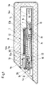
- the receiving housing 2 is arranged, in which on the Double pull-out guides 3a, 3b of the carriage 4 are guided so as to be longitudinally displaceable.
- a spring 16 is arranged between the receiving housing 2 and the slide 4, which when releasing the lock 21a, 21b by means of the on the cover 4b arranged button 20 releases the carriage 4, the exit path limited by a stop 22 arranged on the receiving housing 2 becomes.
- the carriage 4 includes a bottom 4a, a cover 4b and side walls 4c, on which a rear pair via the joints 6 and a via the joints 5 front pair of pivot arms 7, 8 are pivoted.
- the front pair of swivel arms 8 is longer than the rear pair of Swivel arms 7. This inclines the support plate 11 which is parallel to Floor 4a lies on the carriage 4 when folded up into the outer latching position in a rising from the top 1a of the armrest 1 to the front Slant.
- the carrier plate 11 is arranged with the pawl 31 on the swivel arm 7 Hook 7b held in the carriage 4 against the force of the spring 7a.
- the pawl 31 opens the stop 32 arranged in the receiving housing 2, which the pawl 31st triggers so that the hook 7b is released and the carrier plate 11 under The action of the force of the spring 7a moves into the outer locking position - and there by bolts 41 which engage behind the front pair of swivel arms 8, is blocked.
- the lifting movement of the carrier plate 11 is via a damping element 8b, in which has a ring gear 8a arranged on the front pair of the swivel arms 8 intervenes, braked.
- the notepad 12 is held on the carrier plate 11 with the clip 13, which around the hinge 13a from an active position in which they Notepad 12 holds on its front edge 12a in an inactive position can be pivoted away from the area of the notepad 12, for example what when using so-called "post-it” sticky notes, which both stick to the support plate 11 as well as with each other, is advantageous.
- An edge protector 14 is located on the rear edge 11a of the carrier plate 11 arranged pivotally, which under the action of the force of the spring 14a puts the rear edge 12b of the notepad 12 and this when inserting the Carriage 4 in the housing 2 protects against damage.
- a holder 15 is arranged on the carrier plate 11 in front of the notepad 12, in which a writing instrument 15a can be inserted.
- an illumination 30 on the carrier plate 11 which illuminates the writing surface in the outer latching position.
- This lighting 30 can be done manually or by means of a switch by the movement of the support plate 11 from one rest position to the other Rest position can be switched on or off automatically.
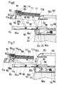
- the receiving housing 102 is arranged, in which The slide 104 is longitudinally displaceable via the double pull-out guides 103a, 103b is stored.
- a tension spring is located between the receiving housing 102 and the slide 104 116 arranged, which when releasing the "double stroke” locking 117, 118th by pressing on the cover 111a arranged on the carrier plate 111 Releases carriage 104 for extension.
- the carriage 104 includes a bottom 104a and side walls 104c on which a rear over the joint 106 and a front over the joint 105 Swivel arm 107, 108 are articulated.
- the carrier plate 111 contains downward-facing side walls 111c on which via the hinge 109 the rear and via the hinge 110 the front Swivel arm 107, 108 are articulated.
- the leg springs 180, 181 are arranged in the region of the joints 105, 106, which push the swivel arms 107, 108 upwards.
- the upper end of the swivel arm 108 is extended beyond the joint 110.
- the extension 108a is arranged on the extension.
- the bolt 190 In the front area of the carrier plate 111, the bolt 190 is about the axis 191 rotatably mounted. A spring 192 presses the latch 190 against the extension 108a.
- the extension 108a runs onto the run-in slope of bolt 190 and directs it against the force of spring 192 forward until the carrier plate 111 has reached the outer latching position and snap the latch 190 under the extension 108a and thus the carrier plate 111 can lock, so that it is secured against pressure from above is.
- the bar 193 attached to the bar 190 By lifting the bar 193 attached to the bar 190, the bar becomes 190 deflected forward against the force of the spring 192, so that the carrier plate 111 against the force of the leg springs 180, 181 on the slide 104 can be lowered.
- the upper end position of the carrier plate 111 is determined by the stop surface 111a determines which of the extension 108a when the support plate 111 is erected accumulates.
- the swivel arm 107 is at its lower end beyond the joint 106 extended.
- a roller 170 is rotatably mounted on the extension 107a.
- a corresponding recess is provided in the bottom 104a, so that the Swing extension 107a down when lifting support plate 111 can.
- a control cam 160 is arranged in the receiving housing 102, against which the roller 170 is pressed and which the position of the swivel arm 107 certainly.
- roller 170 As soon as the roller 170 has reached the driveway 160a, it can swing downwards, so that the support plate 111 can stand up.
- the roller 170 In the outer latching position, the roller 170 is in contact with the driveway 160a and thus prevents the slide 104 from being inserted.
- the roller 170 is pushed upward by the driveway 160a and thereby the carrier plate 111 moves downward so far that the rear end edge 112b of the notepad 112 surely pass the upper housing edge 102b can.
- the two side walls 111c are above the carrier plate 111 extended upwards.
- extensions 111e form the lateral centering for the notepad 112, as well as the side walls for the, in front of the notepad 112 on the carrier plate 111 arranged holder 115, in which a writing instrument 150 are inserted can.
- the bracket 115 is designed as a U-shaped trough.
- a raised support surface 115a is provided in the central region of the holder 115, on which the writing instrument 150 lies.
Landscapes
- Engineering & Computer Science (AREA)
- Mechanical Engineering (AREA)
- Transportation (AREA)
- Aviation & Aerospace Engineering (AREA)
- Vehicle Step Arrangements And Article Storage (AREA)
- Fittings On The Vehicle Exterior For Carrying Loads, And Devices For Holding Or Mounting Articles (AREA)
Description
- Bei Nichtgebrauch ist der Notizblock und das zugehörige Schreibgerät geschützt vor Beschädigungen, Verunreinigungen und Sonneneinstrahlungen im Kfz aufbewahrt.
- Bei Bedarf wird der Notizblock zusammen mit dem Schreibgerät sekundenschnell in optimaler Gebrauchslage im Kfz präsentiert.
- Der Notizblock wird auf einer stabilen Schreibunterlage festgehalten und ist mit bequemer Handauflage einhändig beschriftbar.
- Der Notizblock kann auch bei Dunkelheit verwendet werden.
- Nach Gebrauch lässt sich der Notizblock mit dem zugehörigen Schreibgerät ebenso schnell wieder versorgen. Die Notizen können dabei nicht verloren gehen und sind, vor der Einsicht Dritter geschützt, aufbewahrt.
- Die Vorrichtung ist in einem Hohlraum im Kfz untergebracht und beansprucht keinen Platz im Bereich der Bedienungsflächen von Armaturenbrett und Mittelkonsole.
- Fig. 1
- zeigt im Längsschnitt eine erste Ausführungsform der Vorrichtung in der inneren Raststellung.
- Fig. 2
- zeigt im Längsschnitt die Vorrichtung gemäss Ausführungsform von Fig. 1 mit ausgefahrenem Schlitten und der Trägerplatte in der unteren Endlage.
- Fig. 3
- zeigt im Längsschnitt die Vorrichtung, gemäss Ausführungsform von Fig. 1 und 2 in der äusseren Raststellung.
- Fig. 4
- zeigt eine Detailansicht der Mechanik zur Verriegelung der Trägerplatte in der äusseren Raststellung gemäss Ausführungsform von Fig. 1 bis 3.
- Fig. 5
- zeigt im Längsschnitt eine zweite Ausführungsform der Vorrichtung in der inneren Raststellung.
- Fig. 6
- zeigt im Längsschnitt die Vorrichtung gem. Ausführungsform von Fig. 5 in der äusseren Raststellung.
- Fig. 7
- zeigt im Längsschnitt die Vorrichtung gem. Ausführungsform von Fig. 5 und 6 in einer Zwischenstellung.
- Fig. 8
- zeigt einen Querschnitt im Bereich der Halterung mit eingelegtem Schreibgerät durch die Vorrichtung gem. Ausführungsform von Fig. 5 bis 7 in der äusseren Raststellung.
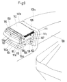
- Fig. 9
- zeigt in perspektivischer Ansicht die Vorrichtung gemäss Fig. 5 bis 8 in der äusseren Raststellung.
Claims (34)
- Vorrichtung, insbesondere zur Aufnahme eines Notizblocks, zum Einbau in Kraftfahrzeuge, mit einem Aufnahmegehäuse (2, 102) zum Einbau in einen Fahrzeugeinbaukörper (1, 100) wie Armlehne, Mittelkonsole od. dgl. und einer, mit dem Aufnahmegehäuse (2, 102) beweglich verbundenen Trägerplatte (11, 111) welche zwischen einer inneren Raststellung, in welcher die Trägerplatte (11, 111) im wesentlichen im Aufnahmegehäuse (2, 102) untergebracht ist, und einer äußeren Raststellung beweglich ist, dadurch gekennzeichnet, daß im Aufnahmegehäuse (2, 102) ein Schlitten (4, 104) längs verschieblich gelagert ist, mit dem die Trägerplatte (11, 111) über Schwenkarme (8, 7, 108, 107) verbunden ist, die quer zur Bewegungsrichtung und von einer Seite des Schlittens (4, 104) gesehen zusammen mit dem Schiffen (4, 104) und der Trägerplatte (11, 111) ein Viereck bilden und mittels derer die Trägerplatte (11, 111) in der äußeren Endlage des Schlittens (4, 104) in die äußere Raststellung anhebbar ist.
- Vorrichtung nach Anspruch 1, dadurch gekennzeichnet, daß die Schwenkarme (8, 7, 108, 107) über Gelenke (5, 6, 105, 106) mit dem Schlitten (4, 104) und über Gelenke (10, 9, 110, 109) mit der Trägerplatte (11, 111) drehbar verbunden sind.
- Vorrichtung nach Anspruch 2, dadurch gekennzeichnet, daß die Gelenke (5, 6, 9, 10, 105, 106, 109, 110) um Achsen quer zur Bewegungsrichtung des Schlittens (4, 104) drehen.
- Vorrichtung nach Anspruch 1, dadurch gekennzeichnet, daß in Ausziehrichtung des Schlittens (4, 104) aus dem Aufnahmegehäuse (2, 102) heraus vordere Schwenkarme (8, 108) länger sind als hintere Schwenkarme (7, 107).
- Vorrichtung nach Anspruch 1, dadurch gekennzeichnet, dass die Schwenkarme (7, 8, 107, 108) so angeordnet sind, dass die Trägerplatte (11, 111) sich entgegen der Ausschubrichtung des Schlittens (4, 104) nach oben bewegt.
- Vorrichtung nach Anspruch 1, dadurch gekennzeichnet, dass die Trägerplatte (11, 111) unter Krafteinwirkung von Federn (16, 116, 7a, 180, 181) von der inneren in die äussere Raststellung bewegt wird.
- Vorrichtung nach Ansprüchen 1 und 6, dadurch gekennzeichnet, dass der Ausschub des Schlittens (4, 104) unter Krafteinwirkung einer Feder (16, 116) erfolgt.
- Vorrichtung nach Anspruch 7, dadurch gekennzeichnet, dass der Schlitten (4, 104) über eine manuell lösbare Verriegelung (21a, 21b, 117, 118) im Aufnahmegehäuse (2, 102) festgehalten wird.
- Vorrichtung nach Ansprüchen 1 und 6, dadurch gekennzeichnet, dass sich die Trägerplatte (11, 111) unter Krafteinwirkung von Federn (7a, 180, 181) vom Schlitten (4, 104) wegbewegt.
- Vorrichtung nach Anspruch 9, dadurch gekennzeichnet, dass Mittel (31, 32, 7b, 107a, 170, 160, 160a, 181) vorgesehen sind, um die Trägerplatte (11, 111) gegen die Kraft der Federn (7a, 180, 181) im Schlitten (4, 104) festzuhalten.
- Vorrichtung nach Anspruch 10, dadurch gekennzeichnet, dass die Mittel (31, 32, 7b, 107a, 170, 160, 160a, 181) beim Erreichen der äusseren Endlage des Schlittens (4, 104) die Trägerplatte (11, 111) freigegeben werden.
- Vorrichtung nach Anspruch 1, dadurch gekennzeichnet, dass die Trägerplatte (11, 111) in der äusseren Raststellung mittels einer Verriegelung (41, 42, 108a, 190, 192) arretiert ist.
- Vorrichtung nach Anspruch 12, dadurch gekennzeichnet, dass die Verriegelung (41, 42, 108a, 190, 192) durch eine an der Trägerplatte (11, 111) angeordnete Auslöseanordnung (20, 40, 193) manuell lösbar ist.
- Vorrichtung nach Anspruch 1, dadurch gekennzeichnet, dass die Trägerplatte (11, 111) über eine Zwangssteuerung (107, 107a, 170, 181, 160, 160a) in Abhängigkeit von der Bewegung des Schlittens (4, 104) angehoben bzw. abgesenkt wird.
- Vorrichtung nach Ansprüchen 1 und 14, dadurch gekennzeichnet, dass die Bewegung eines Schwenkarms (107, 107a, 170) über eine Kurve (160, 160a) gesteuert wird.
- Vorrichtung nach Anspruch 1, dadurch gekennzeichnet, dass Sperrmittel (107a, 170, 160a) vorgesehen sind, welche den Schiffen (4, 104) in seiner äusseren Endlage blockieren und welche durch die Hubbewegung der Trägerplatte (11, 111) aktiviert bzw. inaktiviert werden.
- Vorrichtung nach Anspruch 1, dadurch gekennzeichnet, dass die Gehäuseöffnung am Aufnahmegehäuse (2, 102) in der inneren Raststellung von einer Abdeckung (4b, 111a) verschlossen wird.
- Vorrichtung nach Anspruch 17, dadurch gekennzeichnet, dass die Abdeckung (111a) an der Trägerplatte (11, 111) angeordnet ist.
- Vorrichtung nach Ansprüchen 1 und 17, dadurch gekennzeichnet, dass die Abdeckung (4b) am Schlitten (4, 104) angeordnet ist.
- Vorrichtung nach Anspruch 1, dadurch gekennzeichnet, dass die Gehäuseöffnung am Aufnahmegehäuse (2, 102) auf der, in Fahrtrichtung des Kfz gesehen, vorderen Stirnseite (1b) des Einbaukörpers (1, 100) angeordnet ist.
- Vorrichtung nach Anspruch 1, dadurch gekennzeichnet, dass die Trägerplatte (11, 111) in ihrer äusseren Raststellung, in Fahrtrichtung des Kfz gesehen, vor dem Einbaukörper (1, 100) positioniert ist.
- Vorrichtung nach Anspruch 1, dadurch gekennzeichnet, dass auf der Trägerplatte (11, 111) ein Notizblock (12, 112) angeordnet ist.
- Vorrichtung nach Anspruch 22, dadurch gekennzeichnet, dass an der Trägerplatte (11, 111) eine Klammer (13) angeordnet ist, mittels welcher der Notizblock (12, 112) festgehalten ist.
- Vorrichtung nach Anspruch 23, dadurch gekennzeichnet, dass die Klammer (13) eine aktive und eine inaktive Stellung aufweist.
- Vorrichtung nach Anspruch 22, dadurch gekennzeichnet, dass an der Trägerplatte (11, 111) Zentriermittel (111e) zur seitlichen Begrenzung des Notizblocks (12, 112) angeordnet sind.
- Vorrichtung nach Anspruch 22, dadurch gekennzeichnet, dass ein Kantenschutz (14) vorgesehen ist, welcher die hintere Kante (12b, 112b) des Notizblocks (12, 112) vor Beschädigungen schützt.
- Vorrichtung nach Anspruch 26, dadurch gekennzeichnet, dass der Kantenschutz (14) in der äusseren Raststellung inaktiviert ist.
- Vorrichtung nach Anspruch 1, dadurch gekennzeichnet, dass an der Trägerplatte (11, 111) eine Halterung (15, 115) für ein Schreibgerät (15a, 150) angeordnet ist.
- Vorrichtung nach Ansprüchen 22 und 28, dadurch gekennzeichnet, dass die Halterung (15, 115) vor dem Notizblock (12, 112) angeordnet ist.
- Vorrichtung nach Anspruch 28, dadurch gekennzeichnet, dass die Halterung (15, 115) als U-förmige Wanne ausgebildet ist.
- Vorrichtung nach Anspruch 30, dadurch gekennzeichnet, dass im Mittelbereich der Halterung (15, 115) eine erhöhte Abstützfläche (115a) vorgesehen ist, auf welcher das Schreibgerät (15a, 150) liegt.
- Vorrichtung nach Anspruch 1, dadurch gekennzeichnet, dass an der Trägerplatte (11, 111) eine Beleuchtung (30) angeordnet ist, welche ihre Oberfläche beleuchtet.
- Vorrichtung nach Anspruch 1, dadurch gekennzeichnet, dass die äussere Raststellung der Trägerplatte (11, 111) durch einen Anschlag (108a, 111a) definiert wird.
- Vorrichtung nach Anspruch 33, dadurch gekennzeichnet, dass der Anschlag (108a, 111a) erstellbar ist.
Applications Claiming Priority (3)
| Application Number | Priority Date | Filing Date | Title |
|---|---|---|---|
| CH1835/93 | 1993-06-21 | ||
| CH183593 | 1993-06-21 | ||
| PCT/EP1994/002004 WO1995000360A1 (de) | 1993-06-21 | 1994-06-20 | Vorrichtung, insbesondere zur aufnahme eines notizblocks, zum einbau in kraftfahrzeuge |
Publications (2)
| Publication Number | Publication Date |
|---|---|
| EP0705181A1 EP0705181A1 (de) | 1996-04-10 |
| EP0705181B1 true EP0705181B1 (de) | 1998-08-19 |
Family
ID=4219709
Family Applications (1)
| Application Number | Title | Priority Date | Filing Date |
|---|---|---|---|
| EP94922852A Expired - Lifetime EP0705181B1 (de) | 1993-06-21 | 1994-06-20 | Vorrichtung, insbesondere zur aufnahme eines notizblocks, zum einbau in kraftfahrzeuge |
Country Status (5)
| Country | Link |
|---|---|
| EP (1) | EP0705181B1 (de) |
| AU (1) | AU7263194A (de) |
| DE (1) | DE59406745D1 (de) |
| ES (1) | ES2122310T3 (de) |
| WO (1) | WO1995000360A1 (de) |
Cited By (4)
| Publication number | Priority date | Publication date | Assignee | Title |
|---|---|---|---|---|
| DE10341664B4 (de) * | 2003-09-08 | 2005-12-22 | Adam Opel Ag | Kraftfahrzeug mit zwischen äußeren Sitzen der hinteren Sitzreihe verschiebbarer Mittelkonsole |
| DE102005023602A1 (de) * | 2005-05-18 | 2006-11-23 | Bos Gmbh & Co. Kg | Mittelarmlehne mit Monitor |
| FR3130707A1 (fr) * | 2021-12-17 | 2023-06-23 | Psa Automobiles Sa | Dispositif de tablette escamotable pour véhicule automobile et véhicule automobile comportant un tel dispositif |
| FR3151022A1 (fr) * | 2023-07-13 | 2025-01-17 | Safran Seats | Dispositif de tablette, en particulier pour une unité de siège, et unité de siège comportant un tel dispositif |
Families Citing this family (16)
| Publication number | Priority date | Publication date | Assignee | Title |
|---|---|---|---|---|
| DE29718291U1 (de) * | 1997-10-15 | 1998-01-02 | Grammer Ag, 92224 Amberg | Armlehne für einen Fahrzeugsitz |
| US6220660B1 (en) | 1998-01-02 | 2001-04-24 | Johnson Controls Technology Company | Vehicle activity center |
| WO1999035002A1 (en) * | 1998-01-02 | 1999-07-15 | Johnson Controls Technology Company | Seat back mounted fold down auto office |
| DE10033049A1 (de) * | 2000-07-07 | 2002-01-17 | Volkswagen Ag | Kartenhalter für ein Fahrzeug |
| FR2820798B1 (fr) * | 2001-02-15 | 2003-06-13 | Sagem | Systeme d'entrainement en deplacement d'un panneau pour passagers arriere d'un vehicule |
| DE102004003581A1 (de) * | 2004-01-23 | 2005-08-18 | Karl Heinz Eisele | Ablage-Vorrichtung für Kraftfahrzeuge |
| US7192070B2 (en) | 2004-11-22 | 2007-03-20 | Lear Corporation | Vehicle console with armrest extension |
| DE102006020264B4 (de) * | 2006-04-27 | 2009-12-10 | Grammer Ag | Aufnahmefach für den Innenraum eines Fahrzeugs |
| ES2402629T3 (es) | 2010-11-10 | 2013-05-07 | Tofas Turk Otomobil Fabrikasi Anonim Sirketi | Mecanismo portanotas |
| EP2460686B1 (de) * | 2010-12-06 | 2014-02-12 | Iveco S.p.A. | Fahrzeugtisch und Kühlschrankgehäuse mit einem solchen Tisch |
| DE102012010666A1 (de) | 2012-05-31 | 2013-12-05 | GM Global Technology Operations LLC (n. d. Gesetzen des Staates Delaware) | Armlehnenanordnung für ein Kraftfahrzeug sowieein Kraftfahrzeug mit der Armlehnenanordnung |
| CN105852473B (zh) * | 2016-06-03 | 2018-12-21 | 临海蓝冰科技有限公司 | 一种带防雨功能的园林椅的使用方法 |
| GB2552393A (en) | 2016-06-27 | 2018-01-24 | Liq Meng Corp | Armrest table |
| DE102019003126A1 (de) * | 2019-05-02 | 2020-11-05 | Daimler Ag | Tischvorrichtung für ein Fahrzeug |
| US11866010B2 (en) * | 2021-08-09 | 2024-01-09 | Faurecia Automotive Seating, Llc | Vehicle interior panel assembly having a stowage tray for a mobile device |
| DE102022113126B3 (de) | 2022-05-24 | 2023-09-28 | Audi Aktiengesellschaft | Lagervorrichtung für ein Mobilgerät und Kraftfahrzeug |
Family Cites Families (4)
| Publication number | Priority date | Publication date | Assignee | Title |
|---|---|---|---|---|
| US2522602A (en) * | 1947-11-13 | 1950-09-19 | Edwin J Burns | Writing desk for vehicles |
| US4417764A (en) * | 1981-11-09 | 1983-11-29 | Prince Corporation | Automotive armrest assembly |
| JPS59500413A (ja) * | 1982-03-26 | 1984-03-15 | フオ−ド モ−タ− カンパニ− | ラツチ掛外し自在の摺動トレ−を有するフロアコンソ−ル |
| US4852940A (en) * | 1987-08-20 | 1989-08-01 | Weber Aircraft Corporation | Stowable table system |
-
1994
- 1994-06-20 EP EP94922852A patent/EP0705181B1/de not_active Expired - Lifetime
- 1994-06-20 AU AU72631/94A patent/AU7263194A/en not_active Abandoned
- 1994-06-20 ES ES94922852T patent/ES2122310T3/es not_active Expired - Lifetime
- 1994-06-20 WO PCT/EP1994/002004 patent/WO1995000360A1/de not_active Ceased
- 1994-06-20 DE DE59406745T patent/DE59406745D1/de not_active Expired - Fee Related
Cited By (4)
| Publication number | Priority date | Publication date | Assignee | Title |
|---|---|---|---|---|
| DE10341664B4 (de) * | 2003-09-08 | 2005-12-22 | Adam Opel Ag | Kraftfahrzeug mit zwischen äußeren Sitzen der hinteren Sitzreihe verschiebbarer Mittelkonsole |
| DE102005023602A1 (de) * | 2005-05-18 | 2006-11-23 | Bos Gmbh & Co. Kg | Mittelarmlehne mit Monitor |
| FR3130707A1 (fr) * | 2021-12-17 | 2023-06-23 | Psa Automobiles Sa | Dispositif de tablette escamotable pour véhicule automobile et véhicule automobile comportant un tel dispositif |
| FR3151022A1 (fr) * | 2023-07-13 | 2025-01-17 | Safran Seats | Dispositif de tablette, en particulier pour une unité de siège, et unité de siège comportant un tel dispositif |
Also Published As
| Publication number | Publication date |
|---|---|
| WO1995000360A1 (de) | 1995-01-05 |
| AU7263194A (en) | 1995-01-17 |
| ES2122310T3 (es) | 1998-12-16 |
| DE59406745D1 (de) | 1998-09-24 |
| EP0705181A1 (de) | 1996-04-10 |
Similar Documents
| Publication | Publication Date | Title |
|---|---|---|
| EP0705181A1 (de) | Vorrichtung, insbesondere zur aufnahme eines notizblocks, zum einbau in kraftfahrzeuge | |
| DE102015218735B4 (de) | Mehrzweckarmlehne für ein Fahrzeug | |
| DE112005002760B4 (de) | Fahrzeugsitzverstauvorrichtung | |
| DE102015226812B4 (de) | Klapptischaufbau für Fahrzeuge | |
| DE102005046400B4 (de) | Anordnung zum Halten eines Artikels in einem Fahrzeug | |
| EP0697308B1 (de) | Vorrichtung zum Halten von zwei Getränkebehältnissen in der Mittelkonsole eines Kraftfahrzeuges | |
| DE19516011C1 (de) | Klapptisch für Fahrzeuge | |
| DE102006006294B4 (de) | Dämpfer für einen verstellbaren Fahrzeugsitz | |
| EP0636069B1 (de) | Innenrückspiegel eines kraftfahrzeuges mit integriertem ablagefach | |
| DE4404078A1 (de) | Vorrichtung zum Halten von Getränkebehältern, Trinkgefäßen oder dergleichen | |
| DE102010017182A1 (de) | Fahrradträger eines Fahrzeuges | |
| EP1312501B1 (de) | Anordnung von einem Behältnis und einem Becherhalter für ein Fortbewegungsmittel | |
| EP2620321A2 (de) | Klapptisch | |
| DE102012217944A1 (de) | Armstützenbaugruppe mit Getränkehalter | |
| EP1386778A2 (de) | Drehbeweglicher Körper mit Entrastelement | |
| DE112017004857T5 (de) | Von der Innenverkleidung eines Fahrzeugs anbringbarer und abnehmbarer tragbarer Tisch | |
| DE19534436A1 (de) | Cockpitbereich für eine Beifahrerseite eines Kraftfahrzeugs | |
| DE19946629A1 (de) | Staukastenvorrichtung, insbesondere Dachstaukastenvorrichtung für ein Kraftfahrzeug | |
| DE3624156C1 (en) | Table for vehicles, in particular for motor vehicles | |
| DE102004022835B4 (de) | Kraftfahrzeug mit einer Vorrichtung zur Aufnahme von Gegenständen | |
| WO2000030917A1 (de) | Hebevorrichtung für ein reserverad eines fahrzeugs | |
| DE10137789B4 (de) | Windabweiser für ein Fahrzeugdach | |
| DE102008043638A1 (de) | Objekthalter eines Kraftfahrzeugs | |
| DE19713759C1 (de) | Sonnenblende mit einem Sonnenblendkörper, in dem ein Planspiegel angeordnet ist | |
| DE102007022454A1 (de) | Vorrichtung zum Aufhängen von Gegenständen |
Legal Events
| Date | Code | Title | Description |
|---|---|---|---|
| PUAI | Public reference made under article 153(3) epc to a published international application that has entered the european phase |
Free format text: ORIGINAL CODE: 0009012 |
|
| 17P | Request for examination filed |
Effective date: 19950908 |
|
| AK | Designated contracting states |
Kind code of ref document: A1 Designated state(s): DE ES FR GB IT |
|
| 17Q | First examination report despatched |
Effective date: 19960418 |
|
| GRAG | Despatch of communication of intention to grant |
Free format text: ORIGINAL CODE: EPIDOS AGRA |
|
| GRAG | Despatch of communication of intention to grant |
Free format text: ORIGINAL CODE: EPIDOS AGRA |
|
| GRAH | Despatch of communication of intention to grant a patent |
Free format text: ORIGINAL CODE: EPIDOS IGRA |
|
| GRAH | Despatch of communication of intention to grant a patent |
Free format text: ORIGINAL CODE: EPIDOS IGRA |
|
| GRAA | (expected) grant |
Free format text: ORIGINAL CODE: 0009210 |
|
| AK | Designated contracting states |
Kind code of ref document: B1 Designated state(s): DE ES FR GB IT |
|
| ET | Fr: translation filed | ||
| REF | Corresponds to: |
Ref document number: 59406745 Country of ref document: DE Date of ref document: 19980924 |
|
| GBT | Gb: translation of ep patent filed (gb section 77(6)(a)/1977) |
Effective date: 19981123 |
|
| REG | Reference to a national code |
Ref country code: ES Ref legal event code: FG2A Ref document number: 2122310 Country of ref document: ES Kind code of ref document: T3 |
|
| PLBE | No opposition filed within time limit |
Free format text: ORIGINAL CODE: 0009261 |
|
| STAA | Information on the status of an ep patent application or granted ep patent |
Free format text: STATUS: NO OPPOSITION FILED WITHIN TIME LIMIT |
|
| 26N | No opposition filed | ||
| PGFP | Annual fee paid to national office [announced via postgrant information from national office to epo] |
Ref country code: GB Payment date: 20000614 Year of fee payment: 7 |
|
| PGFP | Annual fee paid to national office [announced via postgrant information from national office to epo] |
Ref country code: FR Payment date: 20000628 Year of fee payment: 7 |
|
| PGFP | Annual fee paid to national office [announced via postgrant information from national office to epo] |
Ref country code: ES Payment date: 20000629 Year of fee payment: 7 |
|
| PG25 | Lapsed in a contracting state [announced via postgrant information from national office to epo] |
Ref country code: GB Free format text: LAPSE BECAUSE OF NON-PAYMENT OF DUE FEES Effective date: 20010620 |
|
| PG25 | Lapsed in a contracting state [announced via postgrant information from national office to epo] |
Ref country code: ES Free format text: LAPSE BECAUSE OF NON-PAYMENT OF DUE FEES Effective date: 20010621 |
|
| GBPC | Gb: european patent ceased through non-payment of renewal fee |
Effective date: 20010620 |
|
| PG25 | Lapsed in a contracting state [announced via postgrant information from national office to epo] |
Ref country code: FR Free format text: LAPSE BECAUSE OF NON-PAYMENT OF DUE FEES Effective date: 20020228 |
|
| REG | Reference to a national code |
Ref country code: ES Ref legal event code: FD2A Effective date: 20030203 |
|
| PG25 | Lapsed in a contracting state [announced via postgrant information from national office to epo] |
Ref country code: IT Free format text: LAPSE BECAUSE OF NON-PAYMENT OF DUE FEES;WARNING: LAPSES OF ITALIAN PATENTS WITH EFFECTIVE DATE BEFORE 2007 MAY HAVE OCCURRED AT ANY TIME BEFORE 2007. THE CORRECT EFFECTIVE DATE MAY BE DIFFERENT FROM THE ONE RECORDED. Effective date: 20050620 |
|
| PGFP | Annual fee paid to national office [announced via postgrant information from national office to epo] |
Ref country code: DE Payment date: 20070314 Year of fee payment: 14 |
|
| PG25 | Lapsed in a contracting state [announced via postgrant information from national office to epo] |
Ref country code: DE Free format text: LAPSE BECAUSE OF NON-PAYMENT OF DUE FEES Effective date: 20090101 |