EP0700502B1 - Refrigerator - Google Patents
Refrigerator Download PDFInfo
- Publication number
- EP0700502B1 EP0700502B1 EP94912556A EP94912556A EP0700502B1 EP 0700502 B1 EP0700502 B1 EP 0700502B1 EP 94912556 A EP94912556 A EP 94912556A EP 94912556 A EP94912556 A EP 94912556A EP 0700502 B1 EP0700502 B1 EP 0700502B1
- Authority
- EP
- European Patent Office
- Prior art keywords
- displacer
- valve disc
- gas
- control openings
- drive cylinder
- Prior art date
- Legal status (The legal status is an assumption and is not a legal conclusion. Google has not performed a legal analysis and makes no representation as to the accuracy of the status listed.)
- Expired - Lifetime
Links
- 238000001816 cooling Methods 0.000 title 1
- 230000000694 effects Effects 0.000 claims description 4
- 230000006735 deficit Effects 0.000 claims description 3
- 239000007789 gas Substances 0.000 description 33
- 230000001133 acceleration Effects 0.000 description 3
- 238000013016 damping Methods 0.000 description 3
- 238000013461 design Methods 0.000 description 3
- 238000006073 displacement reaction Methods 0.000 description 3
- 239000001307 helium Substances 0.000 description 3
- 229910052734 helium Inorganic materials 0.000 description 3
- SWQJXJOGLNCZEY-UHFFFAOYSA-N helium atom Chemical compound [He] SWQJXJOGLNCZEY-UHFFFAOYSA-N 0.000 description 3
- 238000000034 method Methods 0.000 description 2
- 230000006835 compression Effects 0.000 description 1
- 238000007906 compression Methods 0.000 description 1
- 230000001276 controlling effect Effects 0.000 description 1
- 230000001419 dependent effect Effects 0.000 description 1
- 238000005516 engineering process Methods 0.000 description 1
- 238000005259 measurement Methods 0.000 description 1
- 230000000149 penetrating effect Effects 0.000 description 1
- 230000002093 peripheral effect Effects 0.000 description 1
- 238000005057 refrigeration Methods 0.000 description 1
- 230000001105 regulatory effect Effects 0.000 description 1
- 238000012552 review Methods 0.000 description 1
- 238000012546 transfer Methods 0.000 description 1
Images


Classifications
-
- F—MECHANICAL ENGINEERING; LIGHTING; HEATING; WEAPONS; BLASTING
- F25—REFRIGERATION OR COOLING; COMBINED HEATING AND REFRIGERATION SYSTEMS; HEAT PUMP SYSTEMS; MANUFACTURE OR STORAGE OF ICE; LIQUEFACTION SOLIDIFICATION OF GASES
- F25B—REFRIGERATION MACHINES, PLANTS OR SYSTEMS; COMBINED HEATING AND REFRIGERATION SYSTEMS; HEAT PUMP SYSTEMS
- F25B9/00—Compression machines, plants or systems, in which the refrigerant is air or other gas of low boiling point
- F25B9/14—Compression machines, plants or systems, in which the refrigerant is air or other gas of low boiling point characterised by the cycle used, e.g. Stirling cycle
-
- F—MECHANICAL ENGINEERING; LIGHTING; HEATING; WEAPONS; BLASTING
- F25—REFRIGERATION OR COOLING; COMBINED HEATING AND REFRIGERATION SYSTEMS; HEAT PUMP SYSTEMS; MANUFACTURE OR STORAGE OF ICE; LIQUEFACTION SOLIDIFICATION OF GASES
- F25B—REFRIGERATION MACHINES, PLANTS OR SYSTEMS; COMBINED HEATING AND REFRIGERATION SYSTEMS; HEAT PUMP SYSTEMS
- F25B2309/00—Gas cycle refrigeration machines
- F25B2309/006—Gas cycle refrigeration machines using a distributing valve of the rotary type
Definitions
- Refrigerators are cryogenic chillers in which a thermodynamic cycle takes place.
- a one-stage refrigerator includes a work space in which there is a displacer moved between two dead centers OT and UT.
- the A regenerator is assigned through which a Working gas also corresponding to the displacement movement and flows here.
- a Working gas also corresponding to the displacement movement and flows here.
- During the float of the displacer becomes the refrigerator housing in the area of one of the two Dead spots constantly deprived of heat.
- Refrigerators are often designed in two stages (see for example DE-A-38 36 884). With two or three stages Refrigerators can withstand temperatures below 10 K. produce.
- a gas drive generating the reciprocation of the Displacer.
- the warm side of the displacer is one Cylinder-piston device associated with a drive gas is to be supplied.
- Refrigerators of the type affected here must also Control devices are equipped with the help of both the supply of the working gas into the working cylinder as well Supply of the gas drive can be regulated. It is usual, Helium can be used as both working gas and driving gas. In versions of this type, it is sufficient if the Refrigerator is equipped with two connections, one of which one with under high pressure (e.g. 20 bar) and the second with helium under low pressure (e.g. 5 bar) is supplied.
- high pressure e.g. 20 bar
- helium under low pressure e.g. 5 bar
- the present invention has for its object a Operate refrigerator with a gas drive such that a effective reduction of vibrations with relatively simple Measures can be achieved.
- the characterizing Measures of the claims solved is based on the knowledge that the gas drive in known refrigerators during the entire time of the respective movement phases of the Displacer is effective, that is, the displacer during a not inconsiderable during the entire phases of his movement Experiencing acceleration. This leads to the dead centers relatively strong attacks that are responsible for the vibrations are. However, if the displacer corresponds to the Invention only during a fraction of its movement phases accelerated, then its top speeds are in the dead centers and thus its stops on the housing less hard. By controlling the amount of gas with which the gas drive is supplied in both directions of movement, the Drive energy controlled and thus achieved the desired goal become. With the measures according to the invention, the occurring vibrations reduced by more than a factor of 4 become significant without the effectiveness of the refrigerator affect.
- the two-stage refrigerator 1 shown in the figure has a housing, which consists of the two parts 2 and 3. in the Housing part 2 are the cylindrical work spaces 4 and 5 for the two displacement stages 6 and 7 housed.
- the upper displacement stage 6 is on its warm side equipped a drive piston 8, the associated cylinder 9 is housed in a guide bush 10, which is the work space 4 closes towards the housing part 3.
- the guide bush 10 is equipped with holes 11, 12 and 13.
- the Hole 11 opens into the work area 4 and serves the supply this room with working gas.
- the bore 13 opens into one Cross bore 14 with an annular groove 15 in the outer wall the guide bush 10 is connected.
- the bore 12 is through a dash-dotted line indicates and serves the supply of the drive cylinder 9 with drive gas.
- the different Holes are on different levels, so they do not cross each other, what by the dashed respectively Dash-dotted lines are indicated. They all flow into the top of the guide bush 10, which in this area is designed as a fixed valve disk 16.
- a motor 17 is housed, which on the Shaft 18 actuates a rotating valve disk 19.
- the fixed one Valve disc 16 and that under the action of the compression spring 20 standing rotating valve disk 19 form one Control valve that in a manner known per se to supply the different bores with high pressure and low pressure standing gas.
- the working gas and the drive gas are identical. Helium is expediently used.
- the connections for high pressure and low pressure gas are 21 or 22 designated.
- the parting plane 23 between the housing parts 2 and 3 is at the level of the control valve 16, 19. It is chosen so that after removal of the upper housing part 3 with motor 17 and rotating valve disc 19 above the stationary valve disc 16 a flat cup-shaped space 24 is available.
- a wall of the housing part 2 penetrating bore 25 is provided which Room 24 connects to the high pressure port 21.
- the low pressure connection 22 is connected to the bore 26 in the housing part 3, which is at the level of the annular groove 15 of the guide bush 10 flows.
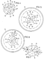
- FIGs 2 and 3 show configurations of the valve disks 16 and 19, with which the desired in the sense of the invention Gas control is possible.
- the fixed, shown in view Valve disc 16 (Fig. 3) leaves the mouths 27, 28, 29th the holes 11, 12 and 13 recognize.
- the bore 13 and its mouth 29 are in the center, during the radial distance of the mouths 27, 28 of the bores 11 and 12 - unlike the prior art - from The axis of rotation of the valve disk 19 is no longer the same (circles 31, 32).
- the mouth 28 of the bore 12 has one much smaller diameter than the mouth 27 of the bore 11.
- the rotating valve disk 19, the design of which is shown in FIG Review through the valve disc 19 is shown rotates according to arrow 33 on the fixed valve disc 16.
- the circle 31 is a through the valve disc 19, bore 34 connected to the high-pressure chamber 24 assigned to a relatively large cross section.
- the district 32 associated recess 35 is a relatively narrow slot designed.
- the valve disc 19 is relative large recess 36 equipped, which extends from Center extends to circle 31. From this recess 36 extends from a slot-shaped recess 37 to District 32.
- Figures 4 and 5 show an embodiment in which in the valve disks 16, 19 each offset by 180 ° Bores 11,11 ', 12,12' and 34,34 'with their associated Mouths are provided.
- the elongated recess 36 extends on both sides of the center to district 31.
- the displacer 6 per revolution of the valve disk 19 twice the number of Lifting movements.
- the open on the circle 31 with the smaller radius Supply holes for the work area 14, the relatively long is to be supplied with high pressure or low pressure.
- the supply holes for gas propulsion Short sweep times are not guaranteed small-sized bores or recesses but also achieved by the higher peripheral speed.
- the speed of the rotating valve disc 19, from the Location and from the design of the mouths 27 to 29, recesses 35 to 37 and bore 34 dependent sweep times for the gas drive it is advisable to choose the following: To effect the movement of the displacer 6 to its cold Side will drive cylinder 9 only during a first Fraction of its total movement time with the high pressure connection 21 connected. This fraction is empirically useful - To be chosen so that the stops of the displacer vibrations caused on the housing are significantly reduced, a significant impairment of the effectiveness of the refrigerator but does not yet occur. The order of magnitude of the A fraction is about a third of the time of the whole Movement time.
- the sweep time is too short choose that the connection between the drive cylinder 9 and the low pressure connection 22 is already closed again, before the displacer reaches its dead center.
- the drive piston will continue to move in the drive cylinder existing gas is compressed, creating a damping effect (Gas cushion) is achieved.
- the pressure increase of the residual gas will appropriately chosen so that shortly before the dead center in the drive cylinder a pressure is reached that is slightly higher than that High pressure level is.
- Figures 6 and 7 show embodiments of the fixed or rotating valve disc, with the help of multiple for acceleration of the displacer 6, 7 in each case for short times is effected.
- Figures 8 and 9 show the effect of these measures.
- the path s of the displacer against the time t is plotted in the upper coordinate system in each case.
- the lower coordinate system shows the times t 1 , t 2 and t 3 at which the drive cylinder 9 is acted upon by high pressure (FIG. 8) or low pressure (FIG. 9).
- Figure 8 shows the course of movement of the displacer from the warm to the cold side.
- the drive cylinder is acted upon by high pressure gas for each time t (for example 5% of the time of the entire movement phase).
- the displacer experiences three brief thrusts that move it towards the cold side, with an alternately accelerated and decelerated movement (movement curve 51).
- the impact of the displacer 6, 7 on the housing 2 (dashed line 52), which is decisive for the vibration, is relatively small.
- the movement of the displacer 6, 7 from the cold to the warm side runs accordingly (cf. movement curve 53 in FIG. 9 with stop line 54).
- the time periods t are chosen so short that a damping gas cushion is created in each case.
- FIGS. 6 to 9 enable one controlled control of the movement of the displacer 6, 7 with the help of short pressure pulses. Compared to continuous accelerated displacers achieved according to the invention displacer 6, 7 moved its dead center to a later one Time; a significant impairment of effectiveness the refrigerator is not connected to it.
Landscapes
- Engineering & Computer Science (AREA)
- Physics & Mathematics (AREA)
- Mechanical Engineering (AREA)
- Thermal Sciences (AREA)
- General Engineering & Computer Science (AREA)
- Compressors, Vaccum Pumps And Other Relevant Systems (AREA)
- Multiple-Way Valves (AREA)
Description
Claims (6)
- Refrigerator mit einem Arbeitsraum (4, 5), in dem sich ein Verdränger (6, 7) hin und her bewegt, mit einem die Verdrängerbewegung bewirkenden Gasantrieb (8, 9), der einen mit der warmen Seite des Verdrängers (6) gekoppelten Antriebskolben (8) und einen alternierend mit Hochdruckgas und Niederdruckgas zu versorgenden Antriebszylinder (9) umfaßt, mit einer Gassteuereinrichtung (16, 19), mit deren Hilfe der Antriebszylinder (9) zeitweise mit dem unter Hochdruck und dem unter Niederdruck stehenden Anschluß (21 bzw. 22) verbunden wird, wobei die Gassteuereinrichtung (16,19) mit einem Gassteuerventil ausgerüstet ist, das eine feststehende Ventilscheibe (16), eine rotierende Ventilscheibe (19) sowie in den Ventilscheiben (16, 19) befindliche Steuer-Öffnungen (27 bis 29, 35 bis 37, 34) aufweist, dadurch gekennzeichnet, daß die Drehzahl der rotierenden Ventilscheibe (19) sowie die Größe und die Lage der in den einander zugewandten Oberflächen der Ventilscheiben (16, 19) befindlichen Steueröffnungen (27 bis 29, 35 bis 37, 34) derart gewählt sind,daß zur Bewegung des Verdrängers (6, 7) von der warmen zur kalten Seite die Verbindung des Antriebszylinders (9) des Gasantriebs (8, 9) mit dem Hochdruckanschluß (21) nur für einen Bruchteil dieser Bewegungsphase hergestellt wird, wobei die Dauer dieses Zeitabschnittes der Bewegungsphase so gewählt wird, dass die durch Anschläge des Verdrängers am Gehäuse verursachten Vibrationen erheblich reduziert sind, eine maßgebliche Beeinträchtigung der Effektivität des Refrigerators jedoch noch nicht eintritt, unddaß zur Bewegung des Verdrängers (6, 7) von der kalten Seite zur warmen Seite im Antriebszylinder (9) ein Niederdruck erzeugt wird, wobei die Niederdruckerzeugung zu Beginn der Verdrängerbewegungsphase so kurzzeitig ist, daß im Antriebszylinder (9) ein die letzte Phase der Verdrängerbewegung dämpfendes Gaspolster entsteht.
- Refrigerator nach Anspruch 1, dadurch gekennzeichnet, daß die der Versorgung des Arbeitsraumes (4, 5) dienenden Steueröffnungen (27, 34, 36) einen anderen radialen Abstand von der Drehachse der Ventilscheibe (19) haben als die der Versorgung des Antriebszylinders (9) dienenden Steueröffnungen (28, 35, 37).
- Refrigerator nach Anspruch 2, dadurch gekennzeichnet, daß der radiale Abstand der der Versorgung des Antriebszylinders (9) dienenden Steueröfffnungen (28, 35, 37) von der Drehachse der Ventilscheibe (19) größer ist als der radiale Abstand der der Versorgung des Arbeitsraumes (4, 5) dienenden Steueröffnungen (27, 34, 36).
- Refrigerator nach Anspruch 2 oder 3, dadurch gekennzeichnet, daß die Abmessungen der der Versorgung des Antriebszylinders (9) dienenden Steueröffnungen (28, 35, 37) kleiner sind als die Abmessungen der der Versorgung des Arbeitsraumes (4, 5) dienenden Steueröffnungen (27, 34, 36).
- Refrigerator nach einem der Ansprüche 1 bis 4, dadurch gekennzeichnet, daß entweder die der Versorgung des Gasantriebes (8, 9) mit Hoch- und Niederdruckgas dienende Steueröffnung (28) in der feststehenden Ventilscheibe (16) oder die dazu korrespondierenden Steueröffnungen (35, 37) in der rotierenden Ventilscheibe (19) in mehrere Steueröffnungen (41 bis 43 bzw. 44 bis 46 und 47 bis 49) unterteilt sind.
- Refrigerator nach einem der Ansprüche 1 bis 5, dadurch gekennzeichnet, daß die Steueröffnungen in den Ventilscheiben (16, 19) zwei- oder mehrfach vorhanden sind, sodaß der Verdränger (6, 7) während einer Umdrehung der Ventilscheibe (16) zwei oder mehr Hübe ausführt.
Applications Claiming Priority (3)
| Application Number | Priority Date | Filing Date | Title |
|---|---|---|---|
| DE4318406A DE4318406A1 (de) | 1993-06-03 | 1993-06-03 | Verfahren zum Betrieb eines Refrigerators und für die Durchführung dieses Verfahrens geeigneter Refrigerator |
| DE4318406 | 1993-06-03 | ||
| PCT/EP1994/001012 WO1994029653A1 (de) | 1993-06-03 | 1994-03-31 | Verfahren zum betrieb eines refrigerators und für die durchführung dieses verfahrens geeigneter refrigerator |
Publications (2)
| Publication Number | Publication Date |
|---|---|
| EP0700502A1 EP0700502A1 (de) | 1996-03-13 |
| EP0700502B1 true EP0700502B1 (de) | 1999-04-21 |
Family
ID=6489514
Family Applications (1)
| Application Number | Title | Priority Date | Filing Date |
|---|---|---|---|
| EP94912556A Expired - Lifetime EP0700502B1 (de) | 1993-06-03 | 1994-03-31 | Refrigerator |
Country Status (4)
| Country | Link |
|---|---|
| EP (1) | EP0700502B1 (de) |
| JP (1) | JP3299970B2 (de) |
| DE (2) | DE4318406A1 (de) |
| WO (1) | WO1994029653A1 (de) |
Families Citing this family (11)
| Publication number | Priority date | Publication date | Assignee | Title |
|---|---|---|---|---|
| DE19510620A1 (de) * | 1995-03-23 | 1996-09-26 | Leybold Ag | Refrigerator |
| DE10152262A1 (de) * | 2001-10-20 | 2003-04-30 | Leybold Vakuum Gmbh | Kaltkopf für eine Tieftempratur-Kältemaschine |
| DE10338221A1 (de) | 2003-08-20 | 2005-03-10 | Leybold Vakuum Gmbh | Kryogener Refrigerator |
| CN100494815C (zh) * | 2004-02-11 | 2009-06-03 | 住友重机械工业株式会社 | 一种多阀两级脉管型gm致冷器和其中使用的三通道回转阀 |
| JP5362518B2 (ja) * | 2009-10-27 | 2013-12-11 | 住友重機械工業株式会社 | ロータリーバルブおよびパルスチューブ冷凍機 |
| DE202013010352U1 (de) * | 2013-11-18 | 2015-02-19 | Oerlikon Leybold Vacuum Gmbh | Kaltkopf für Tieftemperatur-Kältemaschine |
| CN112236630B (zh) * | 2018-04-09 | 2022-01-18 | 爱德华兹真空泵有限责任公司 | 气动驱动制冷机 |
| JP7075816B2 (ja) * | 2018-05-23 | 2022-05-26 | 住友重機械工業株式会社 | 極低温冷凍機のロータリーバルブおよび極低温冷凍機 |
| CN108825841B (zh) * | 2018-07-02 | 2019-08-30 | 广东省新材料研究所 | 一种g-m型低温制冷机旋转阀体及其制备方法 |
| US10808646B2 (en) * | 2019-01-09 | 2020-10-20 | Haier Us Appliance Solutions, Inc. | Cooled piston and cylinder for compressors and engines |
| JP6773872B2 (ja) * | 2019-11-11 | 2020-10-21 | 住友重機械工業株式会社 | Gm冷凍機 |
Family Cites Families (13)
| Publication number | Priority date | Publication date | Assignee | Title |
|---|---|---|---|---|
| US3119237A (en) * | 1962-03-30 | 1964-01-28 | William E Gifford | Gas balancing refrigeration method |
| US3188821A (en) * | 1964-04-13 | 1965-06-15 | Little Inc A | Pneumatically-operated refrigerator with self-regulating valve |
| GB1085439A (en) * | 1965-08-06 | 1967-10-04 | William Ellsworth Gifford | Refrigeration apparatus including a fluid distribution control device |
| US3620029A (en) * | 1969-10-20 | 1971-11-16 | Air Prod & Chem | Refrigeration method and apparatus |
| SU734480A1 (ru) * | 1978-03-27 | 1980-05-15 | Предприятие П/Я М-5727 | Криогенна система |
| US4430863A (en) * | 1982-06-07 | 1984-02-14 | Air Products And Chemicals, Inc. | Apparatus and method for increasing the speed of a displacer-expander refrigerator |
| EP0099654B1 (de) * | 1982-06-30 | 1986-09-10 | British Aerospace Public Limited Company | Vorrichtung zur folgenrichtigen Steuerung von Stirling oder Ericsson, oder ähnlichen Kreisläufen |
| US4543793A (en) * | 1983-08-31 | 1985-10-01 | Helix Technology Corporation | Electronic control of cryogenic refrigerators |
| EP0254759A1 (de) * | 1986-07-29 | 1988-02-03 | Leybold Aktiengesellschaft | Verfahren zum Austauschen des Verdrängers eines Refrigerators und Refrigerator zur Durchführung des Verfahrens |
| US4792346A (en) * | 1987-03-03 | 1988-12-20 | Sarcia Domenico S | Method and apparatus for snubbing the movement of a free, gas-driven displacer in a cooling engine |
| GB8816193D0 (en) * | 1988-07-07 | 1988-08-10 | Boc Group Plc | Improved cryogenic refrigerator |
| US5018357A (en) * | 1988-10-11 | 1991-05-28 | Helix Technology Corporation | Temperature control system for a cryogenic refrigeration |
| DE3836884C2 (de) * | 1988-10-29 | 1997-10-02 | Leybold Ag | Verfahren zur Untersuchung einer auf dem Kaltkopf eines Kryostaten befindlichen Probe und Refrigerator-Kryostat |
-
1993
- 1993-06-03 DE DE4318406A patent/DE4318406A1/de not_active Withdrawn
-
1994
- 1994-03-31 WO PCT/EP1994/001012 patent/WO1994029653A1/de not_active Ceased
- 1994-03-31 JP JP50122095A patent/JP3299970B2/ja not_active Expired - Fee Related
- 1994-03-31 EP EP94912556A patent/EP0700502B1/de not_active Expired - Lifetime
- 1994-03-31 DE DE59408146T patent/DE59408146D1/de not_active Expired - Lifetime
Also Published As
| Publication number | Publication date |
|---|---|
| DE59408146D1 (de) | 1999-05-27 |
| JP3299970B2 (ja) | 2002-07-08 |
| WO1994029653A1 (de) | 1994-12-22 |
| DE4318406A1 (de) | 1994-12-08 |
| JPH09500950A (ja) | 1997-01-28 |
| EP0700502A1 (de) | 1996-03-13 |
Similar Documents
| Publication | Publication Date | Title |
|---|---|---|
| DE4219550C2 (de) | Ausströmdämpfer für einen Kühlungskompressor | |
| DE2051203C2 (de) | Gaskältemaschine | |
| DE4318406A1 (de) | Verfahren zum Betrieb eines Refrigerators und für die Durchführung dieses Verfahrens geeigneter Refrigerator | |
| DE2516591A1 (de) | Gaskaeltemaschine | |
| DE3446480C2 (de) | Gas-Kältemaschine | |
| DE4218631C2 (de) | Kühlungskompressor mit einem profilierten Kolben | |
| DE102006009232A1 (de) | Linearverdichter und Antriebsaggregat dafür | |
| DE102017116805A1 (de) | Tieftemperatur-expander mit kragenstossleiste für reduzierte lärm- und vibrationseigenschaften | |
| EP0160808A1 (de) | Kältemaschine | |
| DD202747A5 (de) | Expansionsmaschine, insbesondere stirling-flugkolbenmaschine und verfahren zu ihrer pneumodynamischen schmierung | |
| CH654402A5 (de) | Verdraenger fuer refrigeratoren. | |
| EP0437661A1 (de) | Kaltkopf mit einem nach dem Gifford/Mc Mahon-Prinzip arbeitenden Refrigerator | |
| DE3049985C2 (de) | ||
| DE68911285T2 (de) | Ventilstellglied mit verbesserter Leistung. | |
| DE4022632C2 (de) | Verfahren zum Umwandeln einer Wärmeleistung in eine mechanische Drehbewegung sowie Vorrichtung zum Durchführen dieses Verfahrens | |
| DE10237686A1 (de) | Kraftumsetzer | |
| DE3146782A1 (de) | Rotationskolbenmaschine | |
| DE60031931T2 (de) | Kühlgerät für Tieftemperaturgastrennunganlage | |
| DE2022547A1 (de) | Motor mit schwingenden Antriebselementen | |
| DE2715102A1 (de) | Kompressor mit freiflugkolben und hohem verdichtungsgrad | |
| DE3201496A1 (de) | Refrigerator | |
| EP0058131B1 (de) | Schwingungserzeuger | |
| DE1260494B (de) | Als Heissgaskraftmaschine oder insbesondere als Kaltgas-Kuehlmaschine arbeitende Kolbenmaschine | |
| DE102015101726A1 (de) | Stirlingmaschine sowie Anordnung zur Erzeugung von elektrischer Energie | |
| DE944131C (de) | Kolben-Expansionsmaschine |
Legal Events
| Date | Code | Title | Description |
|---|---|---|---|
| PUAI | Public reference made under article 153(3) epc to a published international application that has entered the european phase |
Free format text: ORIGINAL CODE: 0009012 |
|
| 17P | Request for examination filed |
Effective date: 19951031 |
|
| AK | Designated contracting states |
Kind code of ref document: A1 Designated state(s): DE FR GB IT NL |
|
| 17Q | First examination report despatched |
Effective date: 19970221 |
|
| GRAG | Despatch of communication of intention to grant |
Free format text: ORIGINAL CODE: EPIDOS AGRA |
|
| GRAG | Despatch of communication of intention to grant |
Free format text: ORIGINAL CODE: EPIDOS AGRA |
|
| GRAH | Despatch of communication of intention to grant a patent |
Free format text: ORIGINAL CODE: EPIDOS IGRA |
|
| GRAH | Despatch of communication of intention to grant a patent |
Free format text: ORIGINAL CODE: EPIDOS IGRA |
|
| GRAA | (expected) grant |
Free format text: ORIGINAL CODE: 0009210 |
|
| AK | Designated contracting states |
Kind code of ref document: B1 Designated state(s): DE FR GB IT NL |
|
| ITF | It: translation for a ep patent filed | ||
| REF | Corresponds to: |
Ref document number: 59408146 Country of ref document: DE Date of ref document: 19990527 |
|
| ET | Fr: translation filed | ||
| GBT | Gb: translation of ep patent filed (gb section 77(6)(a)/1977) |
Effective date: 19990707 |
|
| PGFP | Annual fee paid to national office [announced via postgrant information from national office to epo] |
Ref country code: FR Payment date: 20000214 Year of fee payment: 7 |
|
| PGFP | Annual fee paid to national office [announced via postgrant information from national office to epo] |
Ref country code: NL Payment date: 20000223 Year of fee payment: 7 |
|
| PLBE | No opposition filed within time limit |
Free format text: ORIGINAL CODE: 0009261 |
|
| STAA | Information on the status of an ep patent application or granted ep patent |
Free format text: STATUS: NO OPPOSITION FILED WITHIN TIME LIMIT |
|
| 26N | No opposition filed | ||
| PG25 | Lapsed in a contracting state [announced via postgrant information from national office to epo] |
Ref country code: NL Free format text: LAPSE BECAUSE OF NON-PAYMENT OF DUE FEES Effective date: 20011001 |
|
| PG25 | Lapsed in a contracting state [announced via postgrant information from national office to epo] |
Ref country code: FR Free format text: LAPSE BECAUSE OF NON-PAYMENT OF DUE FEES Effective date: 20011130 |
|
| NLV4 | Nl: lapsed or anulled due to non-payment of the annual fee |
Effective date: 20011001 |
|
| REG | Reference to a national code |
Ref country code: FR Ref legal event code: ST |
|
| REG | Reference to a national code |
Ref country code: GB Ref legal event code: IF02 |
|
| PG25 | Lapsed in a contracting state [announced via postgrant information from national office to epo] |
Ref country code: IT Free format text: LAPSE BECAUSE OF NON-PAYMENT OF DUE FEES Effective date: 20050331 |
|
| PGFP | Annual fee paid to national office [announced via postgrant information from national office to epo] |
Ref country code: GB Payment date: 20100322 Year of fee payment: 17 |
|
| PGFP | Annual fee paid to national office [announced via postgrant information from national office to epo] |
Ref country code: DE Payment date: 20100324 Year of fee payment: 17 |
|
| GBPC | Gb: european patent ceased through non-payment of renewal fee |
Effective date: 20110331 |
|
| PG25 | Lapsed in a contracting state [announced via postgrant information from national office to epo] |
Ref country code: DE Free format text: LAPSE BECAUSE OF NON-PAYMENT OF DUE FEES Effective date: 20111001 |
|
| REG | Reference to a national code |
Ref country code: DE Ref legal event code: R119 Ref document number: 59408146 Country of ref document: DE Effective date: 20111001 |
|
| PG25 | Lapsed in a contracting state [announced via postgrant information from national office to epo] |
Ref country code: GB Free format text: LAPSE BECAUSE OF NON-PAYMENT OF DUE FEES Effective date: 20110331 |