EP0698575B1 - Hebebühne, insbesondere für Kraftfahrzeuge - Google Patents
Hebebühne, insbesondere für Kraftfahrzeuge Download PDFInfo
- Publication number
- EP0698575B1 EP0698575B1 EP95113417A EP95113417A EP0698575B1 EP 0698575 B1 EP0698575 B1 EP 0698575B1 EP 95113417 A EP95113417 A EP 95113417A EP 95113417 A EP95113417 A EP 95113417A EP 0698575 B1 EP0698575 B1 EP 0698575B1
- Authority
- EP
- European Patent Office
- Prior art keywords
- levers
- lifting
- cylinder units
- platform according
- lifting platform
- Prior art date
- Legal status (The legal status is an assumption and is not a legal conclusion. Google has not performed a legal analysis and makes no representation as to the accuracy of the status listed.)
- Expired - Lifetime
Links
- 230000000694 effects Effects 0.000 claims description 4
- 230000006978 adaptation Effects 0.000 claims description 2
- 230000004308 accommodation Effects 0.000 claims 2
- 230000037431 insertion Effects 0.000 claims 1
- 238000003780 insertion Methods 0.000 claims 1
- 238000005452 bending Methods 0.000 description 8
- 230000001360 synchronised effect Effects 0.000 description 5
- 238000010276 construction Methods 0.000 description 3
- 238000004519 manufacturing process Methods 0.000 description 3
- 230000015572 biosynthetic process Effects 0.000 description 1
- 239000003795 chemical substances by application Substances 0.000 description 1
- 230000003247 decreasing effect Effects 0.000 description 1
- 238000006073 displacement reaction Methods 0.000 description 1
- 230000002349 favourable effect Effects 0.000 description 1
- 239000012530 fluid Substances 0.000 description 1
- 239000010720 hydraulic oil Substances 0.000 description 1
- 238000009434 installation Methods 0.000 description 1
- 210000001503 joint Anatomy 0.000 description 1
- 239000000463 material Substances 0.000 description 1
- 239000000725 suspension Substances 0.000 description 1
- 238000009423 ventilation Methods 0.000 description 1
Images
Classifications
-
- B—PERFORMING OPERATIONS; TRANSPORTING
- B66—HOISTING; LIFTING; HAULING
- B66F—HOISTING, LIFTING, HAULING OR PUSHING, NOT OTHERWISE PROVIDED FOR, e.g. DEVICES WHICH APPLY A LIFTING OR PUSHING FORCE DIRECTLY TO THE SURFACE OF A LOAD
- B66F3/00—Devices, e.g. jacks, adapted for uninterrupted lifting of loads
- B66F3/46—Combinations of several jacks with means for interrelating lifting or lowering movements
-
- B—PERFORMING OPERATIONS; TRANSPORTING
- B66—HOISTING; LIFTING; HAULING
- B66F—HOISTING, LIFTING, HAULING OR PUSHING, NOT OTHERWISE PROVIDED FOR, e.g. DEVICES WHICH APPLY A LIFTING OR PUSHING FORCE DIRECTLY TO THE SURFACE OF A LOAD
- B66F7/00—Lifting frames, e.g. for lifting vehicles; Platform lifts
- B66F7/10—Lifting frames, e.g. for lifting vehicles; Platform lifts with platforms supported directly by jacks
- B66F7/16—Lifting frames, e.g. for lifting vehicles; Platform lifts with platforms supported directly by jacks by one or more hydraulic or pneumatic jacks
- B66F7/20—Lifting frames, e.g. for lifting vehicles; Platform lifts with platforms supported directly by jacks by one or more hydraulic or pneumatic jacks by several jacks with means for maintaining the platforms horizontal during movement
Definitions
- the invention relates to a lifting platform for loads, in particular for Motor vehicles with at least one pair of hydraulic Lift cylinder units, the extendable parts of which each with a receiving member for the load to be lifted, and with a synchronization device for the stroke of the two cylinder units, which is a mechanical link has, over which the extendable parts of the lifting cylinder units with each other are connected.
- the invention has for its object a lift of the beginning designated type to provide a mechanical synchronizing device, the on the one hand a low construction effort, on the other hand an adequate one Synchronism guaranteed without excessive bending moments in the mechanical Generate link that leads to canting movements between Piston rod and cylinder housing or cylinder housing and cylinder guide to lead.
- the invention would in principle also be applicable to lifting platforms have more than one pair of lift cylinder units, each pair by Lever according to the invention would be connected, but beyond that Rare could be interconnected by levers according to the invention, in However, the invention is primarily aimed at motor vehicle lifts that only have a pair of lifting cylinder units, these two Lift cylinder units are arranged completely independently and from each other bear independent support members for the load, apart from the Equal ventilation device, which is necessary precisely because it is in the Cylinder units are two independent props.
- Underfloor lifts Although the invention also applies to lifts in others Arrangement is applicable. With underfloor lifts they are Lift cylinder units sunk in a pit in the underground and the Load links are located at the upper ends of the extendable parts of the lifting cylinder units, which through openings in the Pit cover then above ground level to lift one, for example previously driven over them driven motor vehicle.
- This Underfloor lifts have their peculiarity in that basically the aim is that when lifting only an extendable part of cylindrical cross section easily sealable through a corresponding opening to be moved in the pit cover, and that when lifting everyone other construction elements, including in particular those for the Synchronization device, remain inside the pit.
- the articulated connection between the two levers, which is rigid with the extendable parts of the lifting cylinder units can be connected be executed differently.
- the articulated connection around is essential an axis that is horizontal and perpendicular to the plane that the includes two cylinder axes to transfer the internal Reduce bending moments from one lever to the other.
- a another embodiment additionally sees a possibility of pivoting the Lever about an axis that is parallel to the axes of the lifting cylinder units runs. This makes it possible that the hinge point is no longer on a direct connection line between the cylinder axes lies outside a plane that runs through the cylinder axes, whereby the levers with the imaginary direct connection between the cylinder axes form an obtuse-angled triangle.
- the joint itself can be designed in such a way that it has a certain Length change in the direction of the lever allows a certain To allow adaptation to the distance between the cylinder units.
- levers themselves can also be telescopic be designed to be extendable, so that they are at different cylinder distances can be adapted, making it suitable for lifts of different widths can reduce the variety of components.
- the levers are expediently made from a rigid profile, which in particular has high bending resistance in a vertical plane in which the synchronization adjustment forces have an effect. You can the levers in their cross section from their starting attachment points to the Lift cylinder units starting from the articulation point tapered, because the greatest possible bending moments at the fastening points the lever on the cylinder units occur.
- lifting cylinder units Two types are known, namely those in which the piston rod is attached to the floor with a base and the cylinder housing is the extendable part which extends along the Piston rod moves up or down, and those where that Cylinder housing is attached to the floor and the piston rod is facing up extends.
- Lifting cylinder units with multiple pistons are also known or concentric piston-cylinder arrangements, but in the end can also be classified into these two groups.
- a lateral evasion of the joint should not (see claim 2) can be desired, you can also proceed so that one of the levers at the end a fork and the other lever has a tab at the end that fork and tab forming parallel to the axes of the Lifting cylinder units extending, flat guide surfaces into each other are pluggable and that fork and tab through a perpendicular to the Guide surfaces through bores insertable bolts to a joint are connectable, in which a pivoting movement of the arms about the axes of the Lift cylinder units on the manufacturing, forming and temperature-related tolerances between the contact surfaces limited is. It is useful if the holes in the fork or the Bore in the tab are designed as an elongated hole, so that the ends the lever can be moved relative to one another in the direction of its longitudinal extent are.
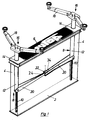
- FIG. 1 is a two-post inground lift for motor vehicles shown. As a complete unit, it can be narrow pit are used and therefore has a base plate 2, Side walls 4 and a cover plate or pit cover 6.
- two Lift cylinder units 8 Arranged in the frame or housing thus formed are two Lift cylinder units 8, the piston rods 10 with their base points on the Base plate 2 are supported.
- Surrounding and in the piston rods 10 Are displaceable in the longitudinal direction relative to these or extendable upwards two cylinder housings 12 are provided.
- the cylinder housing 12 are by two sealingly fitting openings 14 through a guide in the area of Pit cover 6 can be extended above ground.
- the cylinder housing 12 carry load-bearing members 16 at their upper ends to support one Motor vehicle, which in the exemplary embodiment is also provided with swivel arms 18 are provided. The exact training of these load suspension members is from depending on the special application of the lift.
- each is at the bottom Cylinder housing 12 a lever 20 rigidly attached.
- the ends of both levers meet in the middle between the two lifting cylinder units 8 and are there connected by a joint 22.
- the lever 20 is an upwardly open, U-shaped Have cross-sectional profile, which has a considerable bending resistance in vertical direction.
- the levers 20 start from theirs Attachment to the cylinder housing 12 starting from the common Joint point 22 is tapered. This training contributes to Bending moment decreasing bending moment under load and leads thus saving material or lighter components.
- the joint 22 is in the embodiment of FIG. 1 as a joint with a Degree of freedom of movement formed in the plane of the cylinder axes.
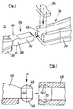
- This Joint is in Fig. 2 in detail, namely in an exploded Representation shown.
- a hinge piece 26 In the end 24 of a left lever 20 is a hinge piece 26 firmly clamped.
- This joint piece 26 has a middle one Joint section 28 with cylindrically curved bearing surfaces 30, the Curvature axis runs in the horizontal direction.
- the middle joint section 28 closes in the direction of one right lever 20 towards an extension 32 with a rectangular cross section, which in Embodiment in the horizontal direction has the same width like the articulated section 28, but less in the vertical direction Thickness as the latter.
- the end 34 of the right lever 20 has a U-shaped Guide cross-section on that with a cover plate 36 to a rectangular Guide channel 38 is screwed.
- this guide channel 38 that is Joint piece 26 insertable, the height of the guide channel 38 of the thickness corresponds to the joint section 28 of the joint piece 26, so that this with its bearing surfaces 30 in approximately linear contact with the upper and reaches the lower limit of the guide channel 38.
- the extension 32 of the Although the width of the joint piece 26 is fitted into the guide channel 38, its thickness in the vertical direction is less than the height of the Guide channel 38, which is behind the cover plate 36 upwards is open.
- FIG 3 is a schematic representation of a joint between levers 20 in exploded view shown in vertical section, which as Ball joint is formed.
- the end 40 of a left lever 20 is with a Articulated head 42, which has a cylindrical base body 44, whose end faces are each provided with a spherical cap 46.
- Corresponding the end 48 of a right lever 20 has two ball sockets 50 as a seat for the spherical caps 46 of the lever end 40.
- the levers are limited against each other in several levels pivotable so that the pivot point between the levers 20 in one horizontal plane is deflectable.
- the lateral evasion of the Hinge point allows adjustment of the two levers 20th existing synchronous connection to dimensional deviations from Inaccuracies in the assembly of the lifting cylinder units 8 can result.
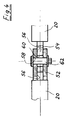
- Figure 4 shows a joint in which a pivoting of the levers 20 about Axes of the lifting cylinder units 8 are to be suppressed.
- the levers 20 have at the end a fork 52 or a tab 54 which can be plugged into one another are, being longitudinally parallel to the axes of the lifting cylinder units 8 extending, flat guide surfaces 56 touch.
- Fork 52 and bracket 54 have bores 58 and 60 in which a bolt 62 perpendicular to the Guide surfaces 56 is inserted. Due to this construction is a Pivotal movement of the arms 20 about the axes of the lifting cylinder units 8 the manufacturing and temperature tolerances between the Contact surfaces 56 limited.
Landscapes
- Life Sciences & Earth Sciences (AREA)
- Engineering & Computer Science (AREA)
- Geology (AREA)
- Mechanical Engineering (AREA)
- Structural Engineering (AREA)
- Actuator (AREA)
- Handcart (AREA)
- Vehicle Cleaning, Maintenance, Repair, Refitting, And Outriggers (AREA)
- Refuge Islands, Traffic Blockers, Or Guard Fence (AREA)
Description
- Da die Krafteinleitung von einem Gleichlaufhebel zum anderen im Gelenk erfolgt, führt der günstige Biegemomentenverlauf mit dem Wert Null in der Gelenkmitte bei der Ausgestaltung und Dimensionierung der Gleichlaufhebel zu leichten und einfachen Bauteilen.
- Wegen der statisch bestimmten Konstruktion, dem Ausgleich von Unparallelität der Zylinder und der Verminderung von Momenten und Spannungen infolge der Nachgiebigkeit der Hebel im Gelenk ergeben sich insgesamt kleinere Bauteilquerschnitte und eine verringerte Führungsreibung in den Zylindern.
- Weiter entsteht durch den Einsatz leichterer, kleinerer und einfacherer Bauteile u.a. ein verminderter Montage-, Lagerhaltungs- und Oberflächenschutzaufwand. Insgesamt werden für die erfindungsgemäße Ausführung nur wenige, leichte und verhältnismäßig einfache Bauteile benötigt und durch die gelenkige Verbindung der Hebel und der dadurch möglichen Auslenkung der Hebelenden aus der die Zylinderachsen verbindenden Ebene, bzw. einer teleskopartigen Verschiebung zwischen den Zylinderachsen bei Einsatz einer Drehmomentenstütze wirken sich Fertigungs- und Montageungenauigkeiten in der Parallelität und im Abstand der beiden Zylinder und ebenso Verformungen weniger kritisch aus.
- Fig. 1
- eine Zweistempel-Unterflurhebebühne mit Gleichlaufeinrichtung in perspektivischer Ansicht,
- Fig. 2
- eine Detaildarstellung eines Gelenkes der Gleichlaufverbindung, mit einem Freiheitsgrad in der Ebene der Zylinderachsen,
- Fig. 3
- eine Detaildarstellung eines als Kugelgelenk ausgebildeten Gelenkes, und
- Fig. 4
- eine alternative Gelenkausbildung.
Claims (14)
- Hebebühne für Lasten, insbesondere für Kraftfahrzeuge, mit mindestens einem Paar von hydraulischen Hubzylindereinheiten, deren ausfahrbare Teile je mit einem Aufnahmeglied für die anzuhebende Last versehen sind, und mit einer Gleichlaufeinrichtung für den Hub der beiden Zylindereinheiten des mindestens einen Paares, die ein mechanisches Verbindungsglied aufweist, über das die ausfahrbaren Teile der Hubzylindereinheiten miteinander verbunden sind, dadurch gekennzeichnet, daß das Verbindungsglied aus zwei Hebeln (20) besteht, von denen je einer starr mit dem ausfahrbaren Teil (12) einer der Hubzylindereinheiten (8) verbunden ist und sich allgemein in Richtung auf die andere Hubzylindereinheit hin erstreckt, und daß die Endpunkte dieser beiden Hebel (20) derart miteinander verbunden sind, daß die Hebel (20) in einer zu den Achsen der Hubzylindereinheiten (8) parallelen Ebene oder der diese Achsen enthaltenden Ebene relativ zueinander eine begrenzte Gelenkigkeit zueinander aufweisen.
- Hebebühne nach Anspruch 1, dadurch gekennzeichnet, daß die Verbindungsstelle (22) außerdem ein begrenztes Schwenken der Hebel (20) um die Achsen der Zylindereinheiten (8) zuläßt.
- Hebebühne nach Anspruch 1, dadurch gekennzeichnet, daß als Verbindungsstelle (20) ein Gelenk, vorzugsweise ein Kugelgelenk, vorgesehen ist.
- Hebebühne nach mindestens einem der Ansprüche 2 oder 3, dadurch gekennzeichnet, daß der Dreh- oder Schwenkpunkt des Gelenkes außerhalb der Ebene liegt, die durch die Achsen der Hubzylindereinheiten (8) verläuft.
- Hebebühne nach mindestens einem der Ansprüche 1-4, dadurch gekennzeichnet, daß die Hebel (20) ein gegen Verbiegen, insbesondere in senkrechter Richtung steifes Querschnittsprofil aufweisen.
- Hebebühne nach mindestens einem der Ansprüche 1-5, dadurch gekennzeichnet, daß die Hebel (20) von ihrem Befestigungsende an der jeweiligen Hubzylindereinheit (8) zu dem gemeinsamen Gelenk (22) hin verjüngt ausgebildet sind.
- Hebebühne nach mindestens einem der Ansprüche 1-5, dadurch gekennzeichnet, daß die Hebel teleskopisch längenanpaßbar ausgebildet sind.
- Hebebühne nach mindestens einem der Ansprüche 1-7, dadurch gekennzeichnet, daß jeder Hebel (20) in einem Bereich an der Hubzylindereinheit (8) befestigt ist, der sich bei eingefahrener Zylindereinheit nahe deren unterstem Bereich befindet.
- Hebebühne nach mindestens einem der Ansprüche 1-7, dadurch gekennzeichnet, daß die Kolbenstange jeder Zylindereinheit ortsfest angeordnet und das Zylindergehäuse der ausfahrbare Teil ist und daß die Hebel (20) im untersten Bereich des Zylindergehäuses (12) an diesem angebracht sind.
- Hebebühne nach Anspruch 8, dadurch gekennzeichnet, daß das Zylindergehäuse jeder Hubzylindereinheit ortsfest angeordnet und eine Kolbenstange der ausfahrbare Teil ist und daß jeder der Hebel an einem Zwischenglied befestigt ist, welches mit der Kolbenstange verbunden ist und sich vom oberen Bereich der Kolbenstange aus am Zylindergehäuse entlang nach unten erstreckt.
- Hebebühne nach mindestens einem der Ansprüche 1-10, dadurch gekennzeichnet, daß sie für Unterfluranordnung in einer Grube ausgebildet ist, daß bei ihr die Aufnahmeglieder für die Last an den oberen Enden der ausfahrbaren Teile der Hubzylindereinheiten angeordnet sind und daß die Hebel (20) derart angeordnet sind, daß sie sich bei eingefahrenen Hubzylindereinheiten (8) im Bereich der Fußpunkte der Hubzylindereinheiten (8) in Nähe des Grubenbodens und bei ausgefahrenen Hubzylindereinheiten (8) unterhalb der Grubenabdeckung (6) befinden.
- Hebebühne nach Anspruch 1, dadurch gekennzeichnet, daß einer der Hebel (20) endseitig eine Gabel (52) und der andere Hebel (20) endseitig eine Lasche (54) aufweist, daß Gabel (52) und Lasche (54) unter Ausbildung von sich parallel zu den Achsen der Hubzylindereinheiten (8) erstreckenden, ebenen Führungsflächen (56) ineinander steckbar sind und daß Gabel (52) und Lasche (54) durch einen senkrecht zu den Führungsflächen (56) durch Bohrungen (58, 60) einsetzbaren Bolzen (62) zu einem Gelenk verbindbar sind.
- Hebebühne nach Anspruch 12, dadurch gekennzeichnet, daß die Bohrungen (58) in der Gabel (52) oder die Bohrung (60) in der Lasche (54) als Langloch ausgebildet sind (ist), so daß die Enden der Hebel (20) in Richtung zu deren Längserstreckung relativ zueinander bewegbar sind.
- Hebebühne nach Anspruch 12 oder 13, dadurch gekennzeichnet, daß eine Schwenkbewegung der Arme (20) um die Achsen der Hubzylindereinheiten (8) auf bestimmte Toleranzen zwischen den Berührungsflächen (56) beschränkt ist.
Applications Claiming Priority (4)
| Application Number | Priority Date | Filing Date | Title |
|---|---|---|---|
| DE4430419 | 1994-08-26 | ||
| DE4430419 | 1994-08-26 | ||
| DE19505366 | 1995-02-17 | ||
| DE19505366A DE19505366A1 (de) | 1994-08-26 | 1995-02-17 | Hebebühne, insbesondere für Kraftfahrzeuge |
Publications (2)
| Publication Number | Publication Date |
|---|---|
| EP0698575A1 EP0698575A1 (de) | 1996-02-28 |
| EP0698575B1 true EP0698575B1 (de) | 1999-11-17 |
Family
ID=25939566
Family Applications (1)
| Application Number | Title | Priority Date | Filing Date |
|---|---|---|---|
| EP95113417A Expired - Lifetime EP0698575B1 (de) | 1994-08-26 | 1995-08-26 | Hebebühne, insbesondere für Kraftfahrzeuge |
Country Status (3)
| Country | Link |
|---|---|
| EP (1) | EP0698575B1 (de) |
| AT (1) | ATE186708T1 (de) |
| DE (1) | DE29508251U1 (de) |
Cited By (1)
| Publication number | Priority date | Publication date | Assignee | Title |
|---|---|---|---|---|
| DE202007002790U1 (de) | 2007-02-22 | 2008-06-26 | Autop Maschinenbau Gmbh | Gleichlaufeinrichtung für Hubvorrichtungen |
Families Citing this family (3)
| Publication number | Priority date | Publication date | Assignee | Title |
|---|---|---|---|---|
| DE19824081C2 (de) * | 1998-05-29 | 2001-09-13 | Autoperkute Maschb Gmbh | Hubvorrichtung, insbesondere Hebebühne für Kraftfahrzeuge |
| DE102008017889B4 (de) * | 2008-04-09 | 2021-07-01 | Dr. Ing. H.C. F. Porsche Aktiengesellschaft | Abnahmestation zur Entnahme eines Personenkraftwagens aus einem Ladungsträger |
| DE102009029718A1 (de) * | 2009-06-16 | 2010-12-30 | Winkel Gmbh | Palettenaufgabestation |
Family Cites Families (8)
| Publication number | Priority date | Publication date | Assignee | Title |
|---|---|---|---|---|
| US3279562A (en) | 1964-07-17 | 1966-10-18 | Dover Corp | Equalizer for a vehicle lift |
| DE3008626A1 (de) * | 1979-03-06 | 1980-09-11 | Pedersen H E H | Wagenheber |
| SU1337343A1 (ru) * | 1986-04-24 | 1987-09-15 | Государственный Проектно-Конструкторский И Технологический Институт "Индустройпроект" | Подъемник |
| DE3824563A1 (de) * | 1988-07-19 | 1990-02-08 | Delu Luftkissen | Verfahren und einrichtung zum anheben und abstuetzen schwerer grossraeumiger lasten, insbesondere von schienengebundenen wagons auf mehreren vorgegebenen arbeitshoehen |
| DE8907280U1 (de) | 1989-06-14 | 1989-07-27 | Slift Hebezeug GmbH, 7533 Tiefenbronn | Hebebühne |
| DE9102833U1 (de) * | 1990-03-24 | 1991-05-29 | Slift Hebezeug GmbH, 7533 Tiefenbronn | Hebebühne |
| DE9003685U1 (de) | 1990-03-29 | 1990-06-07 | Franz Hörnstein GmbH & Co. KG, 7100 Heilbronn | Hebebühne für Kraftfahrzeuge |
| DE9006739U1 (de) * | 1990-06-15 | 1990-08-23 | Slift Hebezeug GmbH, 7533 Tiefenbronn | Gleichlaufvorrichtung für eine Hebebühne |
-
1995
- 1995-02-17 DE DE29508251U patent/DE29508251U1/de not_active Expired - Lifetime
- 1995-08-26 EP EP95113417A patent/EP0698575B1/de not_active Expired - Lifetime
- 1995-08-26 AT AT95113417T patent/ATE186708T1/de active
Cited By (1)
| Publication number | Priority date | Publication date | Assignee | Title |
|---|---|---|---|---|
| DE202007002790U1 (de) | 2007-02-22 | 2008-06-26 | Autop Maschinenbau Gmbh | Gleichlaufeinrichtung für Hubvorrichtungen |
Also Published As
| Publication number | Publication date |
|---|---|
| DE29508251U1 (de) | 1995-09-28 |
| ATE186708T1 (de) | 1999-12-15 |
| EP0698575A1 (de) | 1996-02-28 |
Similar Documents
| Publication | Publication Date | Title |
|---|---|---|
| EP0983897B1 (de) | Hebevorrichtung | |
| DE102007007101B4 (de) | Hebevorrichtung | |
| DE4430543A1 (de) | Hubvorrichtung | |
| DE10347571A1 (de) | Druckwerk | |
| EP0967172B1 (de) | Handhabungsgerät mit Balancier-Hebeeinrichtung | |
| DE2455988A1 (de) | Nach der seite und nach vorn kippbarer hubstaplermast | |
| EP0613852A1 (de) | Scherenhubtisch | |
| DE7827146U1 (de) | Vorrichtung zum Absenken oder Anheben der oberen Plattform eines Fahrzeug-Transporters | |
| DE2233281A1 (de) | Hubgeruest fuer einen hublader | |
| DE19623580C2 (de) | Hubsäule | |
| DE19612091C2 (de) | Hubsäule | |
| EP4110563B1 (de) | Kompaktes 6-achs-positioniersystem | |
| DE2727655C3 (de) | Fahrbare Grubenausbaueinheit | |
| DE10347573A1 (de) | Druckwerk und ein Verfahren zum Bewegen eines Gestellteils | |
| EP0698575A1 (de) | Hebebühne, insbesondere für Kraftfahrzeuge | |
| DE2834498B2 (de) | Garage zum Abstellen von Fahrzeugen übereinander | |
| DE19505366A1 (de) | Hebebühne, insbesondere für Kraftfahrzeuge | |
| DE10154415B4 (de) | Hubwagen mit einer auf- und abbewegbaren Aufnahmeplatte | |
| DE3619124C2 (de) | ||
| DE4110681C2 (de) | ||
| EP0054678B1 (de) | Vorrichtung zum Abstellen mehrerer Fahrzeuge übereinander | |
| EP0184002B1 (de) | Parkeinrichtung für Kraftfahrzeuge | |
| EP0960849A2 (de) | Hubvorrichtung, insbesondere Hebebühne für Kraftfahrzeuge | |
| EP3609831B1 (de) | Hebebühne | |
| DE19525052B4 (de) | Scherenhebebühne |
Legal Events
| Date | Code | Title | Description |
|---|---|---|---|
| PUAI | Public reference made under article 153(3) epc to a published international application that has entered the european phase |
Free format text: ORIGINAL CODE: 0009012 |
|
| AK | Designated contracting states |
Kind code of ref document: A1 Designated state(s): AT BE CH DE FR GB IT LI NL |
|
| 17P | Request for examination filed |
Effective date: 19960809 |
|
| RAP1 | Party data changed (applicant data changed or rights of an application transferred) |
Owner name: AUTOPERKUTE MASCHINENBAU GMBH |
|
| 17Q | First examination report despatched |
Effective date: 19980313 |
|
| GRAG | Despatch of communication of intention to grant |
Free format text: ORIGINAL CODE: EPIDOS AGRA |
|
| GRAG | Despatch of communication of intention to grant |
Free format text: ORIGINAL CODE: EPIDOS AGRA |
|
| GRAH | Despatch of communication of intention to grant a patent |
Free format text: ORIGINAL CODE: EPIDOS IGRA |
|
| GRAH | Despatch of communication of intention to grant a patent |
Free format text: ORIGINAL CODE: EPIDOS IGRA |
|
| GRAA | (expected) grant |
Free format text: ORIGINAL CODE: 0009210 |
|
| AK | Designated contracting states |
Kind code of ref document: B1 Designated state(s): AT BE CH DE FR GB IT LI NL |
|
| REF | Corresponds to: |
Ref document number: 186708 Country of ref document: AT Date of ref document: 19991215 Kind code of ref document: T |
|
| ITF | It: translation for a ep patent filed | ||
| ET | Fr: translation filed | ||
| REG | Reference to a national code |
Ref country code: CH Ref legal event code: EP |
|
| GBT | Gb: translation of ep patent filed (gb section 77(6)(a)/1977) |
Effective date: 19991117 |
|
| REF | Corresponds to: |
Ref document number: 59507237 Country of ref document: DE Date of ref document: 19991223 |
|
| PG25 | Lapsed in a contracting state [announced via postgrant information from national office to epo] |
Ref country code: LI Free format text: LAPSE BECAUSE OF NON-PAYMENT OF DUE FEES Effective date: 20000831 Ref country code: CH Free format text: LAPSE BECAUSE OF NON-PAYMENT OF DUE FEES Effective date: 20000831 |
|
| PLBE | No opposition filed within time limit |
Free format text: ORIGINAL CODE: 0009261 |
|
| STAA | Information on the status of an ep patent application or granted ep patent |
Free format text: STATUS: NO OPPOSITION FILED WITHIN TIME LIMIT |
|
| 26N | No opposition filed | ||
| REG | Reference to a national code |
Ref country code: CH Ref legal event code: PL |
|
| NLT1 | Nl: modifications of names registered in virtue of documents presented to the patent office pursuant to art. 16 a, paragraph 1 |
Owner name: AUTOP MASCHINENBAU GMBH |
|
| REG | Reference to a national code |
Ref country code: GB Ref legal event code: IF02 |
|
| PGFP | Annual fee paid to national office [announced via postgrant information from national office to epo] |
Ref country code: AT Payment date: 20110728 Year of fee payment: 17 Ref country code: GB Payment date: 20110705 Year of fee payment: 17 |
|
| PGFP | Annual fee paid to national office [announced via postgrant information from national office to epo] |
Ref country code: IT Payment date: 20110804 Year of fee payment: 17 Ref country code: NL Payment date: 20110901 Year of fee payment: 17 |
|
| PGFP | Annual fee paid to national office [announced via postgrant information from national office to epo] |
Ref country code: BE Payment date: 20120619 Year of fee payment: 18 |
|
| PGFP | Annual fee paid to national office [announced via postgrant information from national office to epo] |
Ref country code: FR Payment date: 20120717 Year of fee payment: 18 Ref country code: DE Payment date: 20120611 Year of fee payment: 18 |
|
| REG | Reference to a national code |
Ref country code: NL Ref legal event code: V1 Effective date: 20130301 |
|
| REG | Reference to a national code |
Ref country code: AT Ref legal event code: MM01 Ref document number: 186708 Country of ref document: AT Kind code of ref document: T Effective date: 20120826 |
|
| GBPC | Gb: european patent ceased through non-payment of renewal fee |
Effective date: 20120826 |
|
| PG25 | Lapsed in a contracting state [announced via postgrant information from national office to epo] |
Ref country code: NL Free format text: LAPSE BECAUSE OF NON-PAYMENT OF DUE FEES Effective date: 20130301 |
|
| PG25 | Lapsed in a contracting state [announced via postgrant information from national office to epo] |
Ref country code: IT Free format text: LAPSE BECAUSE OF NON-PAYMENT OF DUE FEES Effective date: 20120826 |
|
| PG25 | Lapsed in a contracting state [announced via postgrant information from national office to epo] |
Ref country code: AT Free format text: LAPSE BECAUSE OF NON-PAYMENT OF DUE FEES Effective date: 20120826 |
|
| PG25 | Lapsed in a contracting state [announced via postgrant information from national office to epo] |
Ref country code: GB Free format text: LAPSE BECAUSE OF NON-PAYMENT OF DUE FEES Effective date: 20120826 |
|
| BERE | Be: lapsed |
Owner name: *AUTOP MASCHINENBAU G.M.B.H. Effective date: 20130831 |
|
| PG25 | Lapsed in a contracting state [announced via postgrant information from national office to epo] |
Ref country code: DE Free format text: LAPSE BECAUSE OF NON-PAYMENT OF DUE FEES Effective date: 20140301 |
|
| REG | Reference to a national code |
Ref country code: DE Ref legal event code: R119 Ref document number: 59507237 Country of ref document: DE Effective date: 20140301 |
|
| REG | Reference to a national code |
Ref country code: FR Ref legal event code: ST Effective date: 20140430 |
|
| PG25 | Lapsed in a contracting state [announced via postgrant information from national office to epo] |
Ref country code: BE Free format text: LAPSE BECAUSE OF NON-PAYMENT OF DUE FEES Effective date: 20130831 |
|
| PG25 | Lapsed in a contracting state [announced via postgrant information from national office to epo] |
Ref country code: FR Free format text: LAPSE BECAUSE OF NON-PAYMENT OF DUE FEES Effective date: 20130902 |