EP0698529A1 - Kraftfahrzeuguhr-Federverbindung mit Vibrationsdämpfer - Google Patents
Kraftfahrzeuguhr-Federverbindung mit Vibrationsdämpfer Download PDFInfo
- Publication number
- EP0698529A1 EP0698529A1 EP95303454A EP95303454A EP0698529A1 EP 0698529 A1 EP0698529 A1 EP 0698529A1 EP 95303454 A EP95303454 A EP 95303454A EP 95303454 A EP95303454 A EP 95303454A EP 0698529 A1 EP0698529 A1 EP 0698529A1
- Authority
- EP
- European Patent Office
- Prior art keywords
- clockspring
- housing
- flat cable
- vibration
- vibration dampener
- Prior art date
- Legal status (The legal status is an assumption and is not a legal conclusion. Google has not performed a legal analysis and makes no representation as to the accuracy of the status listed.)
- Withdrawn
Links
- 230000006835 compression Effects 0.000 claims abstract description 13
- 238000007906 compression Methods 0.000 claims abstract description 13
- 239000004020 conductor Substances 0.000 claims description 20
- 239000007769 metal material Substances 0.000 claims description 6
- 229920002799 BoPET Polymers 0.000 claims description 3
- 239000005041 Mylar™ Substances 0.000 claims description 3
- 239000002861 polymer material Substances 0.000 claims description 2
- 239000000463 material Substances 0.000 description 4
- 238000004519 manufacturing process Methods 0.000 description 3
- 230000004048 modification Effects 0.000 description 3
- 238000012986 modification Methods 0.000 description 3
- 229920000728 polyester Polymers 0.000 description 3
- 238000004804 winding Methods 0.000 description 2
- 239000011248 coating agent Substances 0.000 description 1
- 238000000576 coating method Methods 0.000 description 1
- 230000003467 diminishing effect Effects 0.000 description 1
- 238000009434 installation Methods 0.000 description 1
- 238000009413 insulation Methods 0.000 description 1
- 239000012774 insulation material Substances 0.000 description 1
- 230000009916 joint effect Effects 0.000 description 1
- 239000004033 plastic Substances 0.000 description 1
- 229920000642 polymer Polymers 0.000 description 1
- 238000007790 scraping Methods 0.000 description 1
- 230000001052 transient effect Effects 0.000 description 1
Images

Classifications
-
- B—PERFORMING OPERATIONS; TRANSPORTING
- B60—VEHICLES IN GENERAL
- B60R—VEHICLES, VEHICLE FITTINGS, OR VEHICLE PARTS, NOT OTHERWISE PROVIDED FOR
- B60R16/00—Electric or fluid circuits specially adapted for vehicles and not otherwise provided for; Arrangement of elements of electric or fluid circuits specially adapted for vehicles and not otherwise provided for
- B60R16/02—Electric or fluid circuits specially adapted for vehicles and not otherwise provided for; Arrangement of elements of electric or fluid circuits specially adapted for vehicles and not otherwise provided for electric constitutive elements
- B60R16/023—Electric or fluid circuits specially adapted for vehicles and not otherwise provided for; Arrangement of elements of electric or fluid circuits specially adapted for vehicles and not otherwise provided for electric constitutive elements for transmission of signals between vehicle parts or subsystems
- B60R16/027—Electric or fluid circuits specially adapted for vehicles and not otherwise provided for; Arrangement of elements of electric or fluid circuits specially adapted for vehicles and not otherwise provided for electric constitutive elements for transmission of signals between vehicle parts or subsystems between relatively movable parts of the vehicle, e.g. between steering wheel and column
-
- F—MECHANICAL ENGINEERING; LIGHTING; HEATING; WEAPONS; BLASTING
- F16—ENGINEERING ELEMENTS AND UNITS; GENERAL MEASURES FOR PRODUCING AND MAINTAINING EFFECTIVE FUNCTIONING OF MACHINES OR INSTALLATIONS; THERMAL INSULATION IN GENERAL
- F16F—SPRINGS; SHOCK-ABSORBERS; MEANS FOR DAMPING VIBRATION
- F16F1/00—Springs
- F16F1/02—Springs made of steel or other material having low internal friction; Wound, torsion, leaf, cup, ring or the like springs, the material of the spring not being relevant
- F16F1/04—Wound springs
- F16F1/10—Spiral springs with turns lying substantially in plane surfaces
Definitions
- This invention pertains to a clockspring interconnector for enclosing an electrical conductor cable, the clockspring interconnector electrically connecting a rotatable electric device with a stationary electric device.
- An increasing number of automobiles have air bag crash systems.
- An air bag is typically located on the steering wheel facing the driver.
- the air bag must be in continuous electrical connection with sensors in the car body.
- the sensors provide an electrical signal to the air bag crash assembly which instantly inflates the air bag in the event of a crash.
- a clockspring interconnector comprising an outer housing, a rotor member and multiple intermediate housing members for enclosing and connecting the members; the housing and rotor member rotatably associated with one another at a plurality of bearing surfaces.
- a "clockspring” is located inside the interconnector.
- the clockspring is a flat conductor cable and has two ends conductively attached to conductor wires which pass out of the interconnector to unite the air bag to the sensing device.
- the interconnector is mounted on the steering column, and the steering wheel may be rotated in either direction while a continuous, positive electrical connection is provided between air bag sensors via the clockspring interconnector.
- a clockspring interconnector comprising a housing defining a chamber extending therethrough and a rotor cover attached to the housing.
- a coiled flat cable carried within the chamber surrounding the rotor cover. The flat cable having a first end attached to a first connector location of the rotor cover and a second end attached to a second connector location of the housing.
- the chamber includes a vibration dampener preformed to expand upon unwinding of the flat cable and to compress upon winding of the flat cable.
- An outer vibration dampener having preformed bends is located between the flat cable and an exterior housing wall.
- An inner vibration dampener having preformed bends is located between the flat cable and an internal rotor hub. The inner vibration dampener is attached to the inner rotor hub.
- An alternative embodiment of the present invention comprises a vibration dampener pivotally mounted to the housing.
- the vibration dampener includes a first arm and second arm which provide inward compression of a flat conductor cable in a single lateral direction and also inwardly toward the rotor hub.
- the first arm and second arm are joined at a base portion which is mounted to the housing via a post.
- the first arm contacts the flat conductor cable at a first compression point and the second arm contacts the flat conductor cable at a second compression point.
- the vibration dampeners are compressible from an unwound orientation of the clockspring to a wound position of the clockspring.
- the vibration dampener may be formed of either mylar, a metallic material or a metallic material covered in a polymer material.
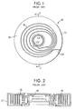
- FIG. 1 shows a clockspring 10 having a housing wall 12 and a rotor hub 14.
- the housing 12 generally has a cover which has been removed from this drawing so that the inside of the clockspring 10 may be viewed.
- a chamber 16 is defined between the housing wall 12 and the rotor wall 14.
- a flat conductor cable 18 is wound within the chamber 16. The flat cable 18 is connected to the nonmovable housing 12 at point 20 and at the opposite end of the flat cable 18 it is connected to the movable rotor 14 at point 22.
- the flat cable 18 is loosely wound within the chamber 16.
- This figure depicts the clockspring in its centered position.
- the clockspring may be turned clockwise which will wind flat cable tighter.
- the clockspring 20 may also be turned counter-clockwise which will unwind the flat cable and make it even looser. It can be seen that there are no objects within the chamber 16 to obstruct the movement of the flat cable 18.
- vibrations occur which cause the flat cable to vibrate against the housing 12 and also against the adjacent flat cable coils. This vibration causes noise which is unsatisfactory.
- the prior art clocksprings in their centered position and their unwound position allow for the flat cable to be loosely wound which causes vibration and unacceptable noise levels.
- FIG. 2 is a side elevation view of FIG. 1 taken at line 2-2. This view shows the housing 12 and rotor 14 defining chamber 16 in which the flat cable 18 is shown. It can be seen that the flat cable is loosely wound having space between the coils. This loosely wound flat cable 18 vibrates uninhibited and provides unsatisfactory noise levels when the clockspring is installed on a steering column.
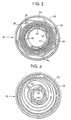
- FIG. 3 shows a preferred embodiment of the present invention having a clockspring housing 30 and rotor hub 32 defining chamber 34.
- the flat cable 36 is attached to the housing 30 at point 38 and its opposite end attached to the rotor hub 32 at point 40.
- Vibration dampeners 42,44 are provided to compress the flat cable 36 in order to limit vibration.
- inner vibration dampener 44 is inserted around the rotor hub 32 and outer vibration dampener 42 is inserted against the housing wall 30.
- the vibration dampener 42,44 may be constructed of an elastic polyester material and preformed to include folds 46.
- the outer vibration dampener 42 is mylar and has five folds 46.
- the inner vibration dampener 44 may be made of a similar polyester material with preformed folds.
- the inner vibration dampener 44 may be attached to the rotor hub 32 at point 40.
- the attachment may occur by any means and may be attached similar to the attachment means of the flat cable 36 at point 40.
- FIG. 3 depicts a clockspring 18 in the centered position similar to the clockspring 10 shown in FIG. 1.
- the clockspring 18 may be wound clockwise which will cause the flat cable 36 to wind tighter, or the clockspring 18 may be turned in a counter-clockwise direction which will cause the flat cable 36 to unwind and loosen.
- the flat cable 36 of clockspring 18 shown in FIG. 3 is compressed so that the spacing between the coils of the flat cable 36 is small. This is unlike the clockspring 10 depicted in FIGS. 1 and 2 in which the clockspring was also in the centered position but the flat cable 18 was loose.
- the use of the vibration dampeners 42,44 having preformed folds 46 cause the vibration dampeners 42,44 to abut against the flat cable 36.
- the outer vibration dampener 42 by maintaining its folds 46 causes abutment points 48 midway between the folds to make contact with the flat cable 36 and compress it inwardly toward the rotor hub 32.
- the inner vibration dampener 44 maintains its folded shape and causes fold points 50 to abut against the flat cable 36 and push the flat cable outwardly toward the housing wall 30.
- the joint action of the inner vibration dampener 50 pushing outward and the outer vibration dampener 42 pushing inward forces the coils of the flat cable 36 to be closely spaced which reduces the amount of vibration between the coils of the flat cable 36 and against the housing 30.
- FIG. 4 shows the clockspring 18 in a totally unwound position wherein the clockspring has been turned counterclockwise from its position in FIG. 3.
- This depiction shows that upon rotation of the clockspring in a counterclockwise direction, the flat cable 36 unwinds and pushes outwardly.
- the outer vibration dampener 42 is of a flexible material which allows it to expand outwardly with the flat cable 36. Thus, the vibration dampeners 42,44 do not inhibit the movement of the flat cable 36 upon rotation of the clockspring 88.
- the outer vibration dampener 42 will retain its folded position as shown in FIG. 3.
- both the inner vibration dampener 44 and the outer vibration dampener 42 are used, within the clockspring 18.
- this invention also anticipates that only the outer vibration dampener 42 may be used or that only the inner vibration dampener 44 may be used to provide a reduction of the noise level caused from the vibration of the flat cable 36.
- the vibration dampeners 42,44 of this invention may also be used in combination with an insulation layer 52 attached to the top and bottom inner surfaces of clockspring 18.
- the vibration dampeners 42,44 may be easily assembled within the housing 30 of the clockspring 18. Following attachment of the flat cable 36 to the housing 30 at point 38 and the rotor hub 32 at point 40, the vibration dampeners 42,44 may simply be inserted next to the flat cable 36. Upon complete assembly of the clockspring by putting a cover over the housing 30, the vibration dampeners 42,44 will be secured within the chamber 34 of the clockspring 18.
- FIG. 5 discloses an alternative embodiment of the present invention having a clockspring housing 130 and rotor hub 132 defining a chamber 134.
- the flat cable 136 is attached to the housing 130 at point 138 and its opposite end attached to the rotor hub 132 at point 140.
- a pair of vibration dampeners 142,144 are provided to compress the flat cable 136 in order to limit vibration.
- the vibration dampener 142,144 may be constructed of an elastic polyester material or even a metallic material.
- the vibration dampener 142,144 could also be constructed of a metallic material covered with a plastic or polymer coating.
- the vibration dampeners 142,144 are a unitary member which includes a common base portion 145 which are secured to the housing 130 via posts 147.
- the vibration dampeners 142,144 are shown in FIG. 5 in a compressed state where the clockspring is in a totally wound position and the flat cable 136 is wound tightly around hub 132. As the clockspring is rotated and the flat cable 136 unwinds, it expands and causes the vibration dampeners 142,144 to flex outwardly in direction of arrows 160,161. During any unwinding and winding of the flat cable 136, the vibration dampeners 142,144 apply pressure to the conductor cable 136 at a first compression point 152 and a second compression point 154. The vibration dampeners 142,144 apply an inward force against the conductor cable 136 toward the hub 132 and simultaneously apply a force laterally in direction of arrow 162.
- the vibration dampener includes a first arm 142 and a second arm 144, each arm attached to the clockspring housing 130 and being pivotally mounted thereto.
Landscapes
- Engineering & Computer Science (AREA)
- General Engineering & Computer Science (AREA)
- Mechanical Engineering (AREA)
- Steering Controls (AREA)
- Springs (AREA)
- Electric Cable Arrangement Between Relatively Moving Parts (AREA)
- Air Bags (AREA)
Applications Claiming Priority (2)
| Application Number | Priority Date | Filing Date | Title |
|---|---|---|---|
| US08/285,072 US5490793A (en) | 1994-03-11 | 1994-08-03 | Automobile clockspring with vibration dampener |
| US285072 | 1994-08-03 |
Publications (1)
| Publication Number | Publication Date |
|---|---|
| EP0698529A1 true EP0698529A1 (de) | 1996-02-28 |
Family
ID=23092620
Family Applications (1)
| Application Number | Title | Priority Date | Filing Date |
|---|---|---|---|
| EP95303454A Withdrawn EP0698529A1 (de) | 1994-08-03 | 1995-05-23 | Kraftfahrzeuguhr-Federverbindung mit Vibrationsdämpfer |
Country Status (6)
| Country | Link |
|---|---|
| US (1) | US5490793A (de) |
| EP (1) | EP0698529A1 (de) |
| JP (1) | JPH0864327A (de) |
| KR (1) | KR960007408A (de) |
| CN (1) | CN1122961A (de) |
| CA (1) | CA2149702A1 (de) |
Cited By (1)
| Publication number | Priority date | Publication date | Assignee | Title |
|---|---|---|---|---|
| CN104755790A (zh) * | 2012-12-13 | 2015-07-01 | 新确有限公司 | 盘簧 |
Families Citing this family (13)
| Publication number | Priority date | Publication date | Assignee | Title |
|---|---|---|---|---|
| US6095836A (en) * | 1994-07-19 | 2000-08-01 | Methode Electronics, Inc. | Clockspring connector with carrier member |
| US6213797B1 (en) | 1994-07-19 | 2001-04-10 | Methode Electronics, Inc. | Clockspring having non-compliant and compliant roller members |
| US6012935A (en) * | 1994-07-19 | 2000-01-11 | Methode Electronics, Inc. | Clockspring connector with carrier member |
| US5749744A (en) * | 1996-06-26 | 1998-05-12 | Henderson; Brent E. | Electrical connector with EMI/RFI shielding |
| US6126461A (en) * | 1999-03-18 | 2000-10-03 | Methode Electronics, Inc. | Sound dampening spring fingers to reduce hub/rotor vibration noise |
| US6164994A (en) * | 1999-09-24 | 2000-12-26 | Methode Electronics, Inc. | Loop back clockspring having adhesive layer |
| US6439495B1 (en) * | 1999-09-24 | 2002-08-27 | Methode Electronics, Inc. | Loop back clockspring having adhesive layer |
| US6425774B1 (en) * | 1999-11-11 | 2002-07-30 | Autonetworks Technologies, Ltd. | Rotary connection device |
| US6217355B1 (en) | 1999-12-07 | 2001-04-17 | Methode Electronics, Inc. | Compressed air clockspring |
| JP4829068B2 (ja) * | 2006-10-12 | 2011-11-30 | 株式会社クレハ | 収納容器付きスプール |
| US9557192B2 (en) * | 2015-01-16 | 2017-01-31 | Alps Electric Co., Ltd. | Electronic centering indicator for clockspring assembly |
| FR3051986B1 (fr) * | 2016-05-26 | 2018-05-18 | Renault S.A.S | Dispositif portatif de devidage d'un cable electrique, notamment un cable de charge pour un vehicule electrique ou hybride |
| WO2018105623A1 (ja) * | 2016-12-06 | 2018-06-14 | 古河電気工業株式会社 | 緩衝部材及び回転コネクタ装置 |
Citations (5)
| Publication number | Priority date | Publication date | Assignee | Title |
|---|---|---|---|---|
| EP0186935A1 (de) * | 1984-11-13 | 1986-07-09 | Sheller-Globe Corporation | Schraubenförmiges flexibles Kreissystem für Lenkräder |
| US4925122A (en) | 1988-04-20 | 1990-05-15 | Alps Electric Co., Ltd. | Cable reel |
| DE4004233A1 (de) * | 1989-02-14 | 1990-08-16 | Furukawa Electric Co Ltd | Verbindungsvorrichtung |
| EP0387585A1 (de) * | 1989-02-28 | 1990-09-19 | W.L. Gore & Associates GmbH | Flacchkabelspirale |
| EP0401028A2 (de) * | 1989-05-31 | 1990-12-05 | The Furukawa Electric Co., Ltd. | Verbindervorrichtung |
Family Cites Families (2)
| Publication number | Priority date | Publication date | Assignee | Title |
|---|---|---|---|---|
| JPH0389059U (de) * | 1989-12-26 | 1991-09-11 | ||
| JPH0541088A (ja) * | 1991-08-06 | 1993-02-19 | Nec Ic Microcomput Syst Ltd | 半導体集積回路 |
-
1994
- 1994-08-03 US US08/285,072 patent/US5490793A/en not_active Expired - Lifetime
-
1995
- 1995-05-18 CA CA002149702A patent/CA2149702A1/en not_active Abandoned
- 1995-05-23 EP EP95303454A patent/EP0698529A1/de not_active Withdrawn
- 1995-06-20 JP JP7153310A patent/JPH0864327A/ja active Pending
- 1995-07-28 CN CN95115303A patent/CN1122961A/zh active Pending
- 1995-07-31 KR KR1019950023219A patent/KR960007408A/ko not_active Withdrawn
Patent Citations (5)
| Publication number | Priority date | Publication date | Assignee | Title |
|---|---|---|---|---|
| EP0186935A1 (de) * | 1984-11-13 | 1986-07-09 | Sheller-Globe Corporation | Schraubenförmiges flexibles Kreissystem für Lenkräder |
| US4925122A (en) | 1988-04-20 | 1990-05-15 | Alps Electric Co., Ltd. | Cable reel |
| DE4004233A1 (de) * | 1989-02-14 | 1990-08-16 | Furukawa Electric Co Ltd | Verbindungsvorrichtung |
| EP0387585A1 (de) * | 1989-02-28 | 1990-09-19 | W.L. Gore & Associates GmbH | Flacchkabelspirale |
| EP0401028A2 (de) * | 1989-05-31 | 1990-12-05 | The Furukawa Electric Co., Ltd. | Verbindervorrichtung |
Cited By (2)
| Publication number | Priority date | Publication date | Assignee | Title |
|---|---|---|---|---|
| CN104755790A (zh) * | 2012-12-13 | 2015-07-01 | 新确有限公司 | 盘簧 |
| CN104755790B (zh) * | 2012-12-13 | 2017-03-01 | 新确有限公司 | 盘簧 |
Also Published As
| Publication number | Publication date |
|---|---|
| CN1122961A (zh) | 1996-05-22 |
| KR960007408A (ko) | 1996-03-22 |
| US5490793A (en) | 1996-02-13 |
| CA2149702A1 (en) | 1996-02-04 |
| JPH0864327A (ja) | 1996-03-08 |
Similar Documents
| Publication | Publication Date | Title |
|---|---|---|
| US5490793A (en) | Automobile clockspring with vibration dampener | |
| US5487667A (en) | Automobile clockspring with vibration dampener | |
| US5310356A (en) | Transmission device used between two relatively rotatable components | |
| EP0695000A2 (de) | Drehbarer Verbinder mit Trägerelement | |
| US5980285A (en) | Rotary connector apparatus | |
| JP3393762B2 (ja) | 車載用回転コネクタ | |
| US5314341A (en) | Electrical connector device | |
| US5655920A (en) | Clock spring connector | |
| US5980286A (en) | Clockspring connector with compliant roller | |
| US5389002A (en) | Connector apparatus used for a flexible cable | |
| KR100479186B1 (ko) | 에어백 작동 시스템 및 그를 위한 접속 시스템 | |
| JP3476490B2 (ja) | グロメット | |
| US5333914A (en) | Hose device | |
| JP3709998B2 (ja) | 回転コネクタ | |
| JP3846100B2 (ja) | 回転コネクタ | |
| CN111864674B (zh) | 线束 | |
| JP3442612B2 (ja) | グロメット | |
| JPH07169544A (ja) | ケーブルリール | |
| JP3408927B2 (ja) | 回転コネクタ | |
| JP2919234B2 (ja) | ケーブルリール | |
| JP3258880B2 (ja) | 回転コネクタ | |
| JP3595362B2 (ja) | 回転コネクタ装置に於けるハウジング構造 | |
| JPH0737663A (ja) | コネクタ装置 | |
| JPH06251846A (ja) | コネクタ装置 | |
| JPH07291061A (ja) | 回転体と固定体間の伝送装置 |
Legal Events
| Date | Code | Title | Description |
|---|---|---|---|
| PUAI | Public reference made under article 153(3) epc to a published international application that has entered the european phase |
Free format text: ORIGINAL CODE: 0009012 |
|
| AK | Designated contracting states |
Kind code of ref document: A1 Designated state(s): AT DE ES FR GB NL SE |
|
| 17P | Request for examination filed |
Effective date: 19960315 |
|
| 17Q | First examination report despatched |
Effective date: 19961227 |
|
| STAA | Information on the status of an ep patent application or granted ep patent |
Free format text: STATUS: THE APPLICATION IS DEEMED TO BE WITHDRAWN |
|
| 18D | Application deemed to be withdrawn |
Effective date: 19971202 |