EP0695000A2 - Drehbarer Verbinder mit Trägerelement - Google Patents
Drehbarer Verbinder mit Trägerelement Download PDFInfo
- Publication number
- EP0695000A2 EP0695000A2 EP95304321A EP95304321A EP0695000A2 EP 0695000 A2 EP0695000 A2 EP 0695000A2 EP 95304321 A EP95304321 A EP 95304321A EP 95304321 A EP95304321 A EP 95304321A EP 0695000 A2 EP0695000 A2 EP 0695000A2
- Authority
- EP
- European Patent Office
- Prior art keywords
- hub
- flat conductor
- housing
- clockspring connector
- carrier member
- Prior art date
- Legal status (The legal status is an assumption and is not a legal conclusion. Google has not performed a legal analysis and makes no representation as to the accuracy of the status listed.)
- Withdrawn
Links
- 239000004020 conductor Substances 0.000 claims abstract description 90
- 238000013461 design Methods 0.000 description 3
- 239000000463 material Substances 0.000 description 3
- 238000012986 modification Methods 0.000 description 3
- 230000004048 modification Effects 0.000 description 3
- 125000006850 spacer group Chemical group 0.000 description 2
- 239000004809 Teflon Substances 0.000 description 1
- 229920006362 Teflon® Polymers 0.000 description 1
- 230000003467 diminishing effect Effects 0.000 description 1
- 239000004519 grease Substances 0.000 description 1
- 238000010030 laminating Methods 0.000 description 1
- 238000004519 manufacturing process Methods 0.000 description 1
- 239000002861 polymer material Substances 0.000 description 1
- 238000003672 processing method Methods 0.000 description 1
- 239000002210 silicon-based material Substances 0.000 description 1
- 229920001169 thermoplastic Polymers 0.000 description 1
- 238000012546 transfer Methods 0.000 description 1
- 230000001052 transient effect Effects 0.000 description 1
- 238000004804 winding Methods 0.000 description 1
Images


Classifications
-
- H—ELECTRICITY
- H01—ELECTRIC ELEMENTS
- H01R—ELECTRICALLY-CONDUCTIVE CONNECTIONS; STRUCTURAL ASSOCIATIONS OF A PLURALITY OF MUTUALLY-INSULATED ELECTRICAL CONNECTING ELEMENTS; COUPLING DEVICES; CURRENT COLLECTORS
- H01R35/00—Flexible or turnable line connectors, i.e. the rotation angle being limited
-
- B—PERFORMING OPERATIONS; TRANSPORTING
- B60—VEHICLES IN GENERAL
- B60R—VEHICLES, VEHICLE FITTINGS, OR VEHICLE PARTS, NOT OTHERWISE PROVIDED FOR
- B60R16/00—Electric or fluid circuits specially adapted for vehicles and not otherwise provided for; Arrangement of elements of electric or fluid circuits specially adapted for vehicles and not otherwise provided for
- B60R16/02—Electric or fluid circuits specially adapted for vehicles and not otherwise provided for; Arrangement of elements of electric or fluid circuits specially adapted for vehicles and not otherwise provided for electric constitutive elements
- B60R16/023—Electric or fluid circuits specially adapted for vehicles and not otherwise provided for; Arrangement of elements of electric or fluid circuits specially adapted for vehicles and not otherwise provided for electric constitutive elements for transmission of signals between vehicle parts or subsystems
- B60R16/027—Electric or fluid circuits specially adapted for vehicles and not otherwise provided for; Arrangement of elements of electric or fluid circuits specially adapted for vehicles and not otherwise provided for electric constitutive elements for transmission of signals between vehicle parts or subsystems between relatively movable parts of the vehicle, e.g. between steering wheel and column
-
- H—ELECTRICITY
- H01—ELECTRIC ELEMENTS
- H01R—ELECTRICALLY-CONDUCTIVE CONNECTIONS; STRUCTURAL ASSOCIATIONS OF A PLURALITY OF MUTUALLY-INSULATED ELECTRICAL CONNECTING ELEMENTS; COUPLING DEVICES; CURRENT COLLECTORS
- H01R35/00—Flexible or turnable line connectors, i.e. the rotation angle being limited
- H01R35/02—Flexible line connectors without frictional contact members
- H01R35/025—Flexible line connectors without frictional contact members having a flexible conductor wound around a rotation axis
Definitions
- While the present invention may have multiple applications, the most prevalent is for use in automobiles.
- An increasing number of automobiles have airbag crash systems.
- An airbag is typically located on the steering wheel facing the driver.
- the airbag must be in continuous electrical connection with sensors in the car body.
- the sensors provide an electrical signal to the airbag crash assembly which instantly inflates the airbag in the event of a crash.
- electrical connections between rotatable and stationary parts are well known.
- an electrical brush rests upon a conductive ring, with one of the parts being rotatable to provide such rotatable electrical connection.
- there is a risk, particularly during the impact of an accident of a transient failure of electrical connection with a brush and ring system which result in failure of the entire airbag system crash assembly.
- a clockspring connector comprising an outer housing, a rotor member and a multiple of intermediate housing members for enclosing and connecting the members; the housing and rotor member rotatably associated with one another at a plurality of bearing surfaces.
- a "clockspring" is located inside the interconnector.
- the clockspring of prior art devices includes a single flat conductor cable having its ends conductively attached to conductor wires which pass out of the interconnector to unite the airbag to the sensing device.
- U.S. Patent No. 5,061,195 discloses a clockspring housing and assembly having a single flat conductor cable therein.
- U.S. Patent No. 5,277,604 incorporates an assembly of at least eight rollers and turned-back portions of the flat conductor cable within the clockspring housing to decrease the length of the flat cable and also prevent buckling and enhance reliability and smooth rotation of the clockspring connector.
- Such a design requires a complex and expensive system of mounting the rollers.
- Such a design may be expensive and, as well, only accommodates a single flat conductor cable.
- clockspring connector As more controls are mounted on the steering wheel, more conductors are required to pass multiple electrical signals through the clockspring connector.
- Prior art clocksprings have included conductor cables having up to six conductors in each flat cable. The excess of six conductors is limited by the limited width of the flat conductor cable and the processing methods of manufacturing the flat cable. Accordingly, there is needed a clockspring connector which can accommodate more than six conductors.
- a clockspring connector comprising a housing defining a chamber extending therethrough.
- a carrier member positioned within the chamber having two rollers.
- Flat conductor cable carried by the carrier member.
- the flat conductor cable having a first turned-back loop section associated with a first roller and a second turned-back loop section associated with a second roller.
- a hub having an inner diameter exit cavity for receiving the flat conductor cable.
- rotation of the hub in a clockwise direction causes the first flat conductor cable to unwind from the hub and push against the carrier wall adjacent the first roller and simultaneously the second flat cable unwinds off of the hub and pushes against the second wall of the carrier member adjacent the second roller causing the carrier member to rotate in a clockwise direction and to transfer the first and second flat cables from the hub to the outer diameter of the housing.
- Rotation of the hub in the counterclockwise direction causes the first flat cable to pull on the first roller and the second flat cable to pull on the second roller causing the first and second flat cables to unwind from the outer diameter of the chamber and simultaneously causing the carrier member to rotate in a counterclockwise direction.
- a housing member receives the hub, the carrier member is mounted on the hub, and a cover encloses the carrier member and flat cables within the housing.
- the cover having an outer diameter exit cavity.
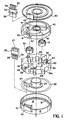
- FIGS. 1-3 show various aspects of a presently preferred clockspring connector.
- a housing 10 receives a hub 20.
- a carrier member 30 Mounted on the hub is a carrier member 30.
- a first flat conductor cable 41 and a second flat conductor cable 42 is carried by the carrier member 30.
- a cover 50 encloses the flat cables 41,42, carrier member 30 and hub 20 within housing 10.
- First and second conductor cables 41,42 exit the clockspring at the outer diameter through the outer diameter exit cavity 52.
- Conductor cable tails 46 are folded perpendicularly to the path of the conductor cables within the chamber 14 and are received by the outer diameter exit cavity 52.
- Outer diameter backbone 54 is received from the other end of the outer diameter exit cavity 52 from the conductor cable tails 46.
- Entrance cavity 56 of the outer diameter backbone 54 receives the first and second conductor cables 41,42.
- the conductors of the cables 41,42 are welded to the corresponding insulated wires 58 which protrude from the exit end 59 of outer diameter backbone 54.
- the first flat conductor cable 41 is spooled out from first roller 31 to completely encircle the outer diameter of the chamber 14 adjacent the wall 15 of the housing 10.
- the second flat conductor 42 is spooled out along second roller 32 at a position 180' from the first conductor cable 41, to provide a second coil layered adjacently to the first conductor cable 41 at the outer diameter of the chamber 14. Rotation of the hub and carrier member 30 continue in the clockwise direction until the flat cables 41,42 are completely unwound from the hub 10.
- the completely unwound condition is shown in FIG. 3.
- Like numerals for like elements of FIG. 2 are shown in FIG. 3.
- the clockspring connector 5 is shown in a completely unwound position, i.e., the flat conductor cables 41,42 are not coiled around hub 20.
- the hub 20 is rotated in a counterclockwise direction in the direction in the direction of arrows 72,73.
- the first flat cable 41 pulls on the first roller 31 at first turned-back loop 43 causing the first roller 31 to rotate.
- second conductor cable 42 pulls on second roller 32 at second turned-back loop 44 causing the second roller 32 to rotate in clockwise direction.
- first and second cable 42 The pulling of the first cable 41 and the second cable 42 on the first and second rollers 31,32 causes the carrier member 30 to rotate in a counterclockwise direction.
- the first and second conductors 41,42 are uncoiled from the outer diameter of the chamber 14 and become coiled again onto the hub 20. It can be seen that in the completely unwound position, the coils are positioned along the outer diameter of the chamber 14 in a first layer 81, a second layer 82, a third layer 83, and a fourth layer 84.
- the first conductor cable 41 and the second conductor cable 42 are alternatingly layered; wherein first layer 81 and third layer 83 are the first conductor cable 41 and the second layer 82 and fourth layer 84 are the second conductor cable 42.
- layer 81 is taken up from the outer diameter of the chamber onto the hub 20 by first roller 31.
- second layer 82 is taken up by second roller 32.
- third layer 83 is taken up by the continued rotation of first roller 31 in the counter-clockwise direction and fourth layer 84 is taken up by second roller 32.
- This alternating take-up sequence is correspondingly achieved along the inner diameter of the chamber 14 by winding the clockspring connector in the clockwise direction spooling first and second conductor cables 41,42 onto the hub 20.
Landscapes
- Engineering & Computer Science (AREA)
- Mechanical Engineering (AREA)
- Steering Controls (AREA)
- Air Bags (AREA)
- Details Of Connecting Devices For Male And Female Coupling (AREA)
Applications Claiming Priority (2)
| Application Number | Priority Date | Filing Date | Title |
|---|---|---|---|
| US27695494A | 1994-09-19 | 1994-09-19 | |
| US276954 | 1999-03-26 |
Publications (2)
| Publication Number | Publication Date |
|---|---|
| EP0695000A2 true EP0695000A2 (de) | 1996-01-31 |
| EP0695000A3 EP0695000A3 (de) | 1996-07-31 |
Family
ID=23058794
Family Applications (1)
| Application Number | Title | Priority Date | Filing Date |
|---|---|---|---|
| EP95304321A Withdrawn EP0695000A3 (de) | 1994-07-19 | 1995-06-21 | Drehbarer Verbinder mit Trägerelement |
Country Status (7)
| Country | Link |
|---|---|
| US (1) | US5865634A (de) |
| EP (1) | EP0695000A3 (de) |
| JP (1) | JPH0855667A (de) |
| KR (1) | KR960006166A (de) |
| CN (1) | CN1122060A (de) |
| CA (1) | CA2151644A1 (de) |
| TW (1) | TW317043B (de) |
Cited By (3)
| Publication number | Priority date | Publication date | Assignee | Title |
|---|---|---|---|---|
| GB2328330A (en) * | 1997-07-10 | 1999-02-17 | Alps Electric Co Ltd | Clockspring connector |
| US5882216A (en) * | 1996-07-15 | 1999-03-16 | Alps Electric Co., Ltd. | Rotary connector |
| DE19920995A1 (de) * | 1998-05-06 | 1999-11-25 | Alps Electric Co Ltd | Drehverbinder |
Families Citing this family (22)
| Publication number | Priority date | Publication date | Assignee | Title |
|---|---|---|---|---|
| US6095836A (en) * | 1994-07-19 | 2000-08-01 | Methode Electronics, Inc. | Clockspring connector with carrier member |
| JP3627554B2 (ja) | 1999-01-20 | 2005-03-09 | 松下電器産業株式会社 | 回転コネクタ |
| JP3561435B2 (ja) * | 1999-05-14 | 2004-09-02 | アルプス電気株式会社 | 車載用回転コネクタ |
| JP3518673B2 (ja) | 1999-06-23 | 2004-04-12 | アルプス電気株式会社 | 車載用回転コネクタ |
| US6439495B1 (en) * | 1999-09-24 | 2002-08-27 | Methode Electronics, Inc. | Loop back clockspring having adhesive layer |
| US6164994A (en) * | 1999-09-24 | 2000-12-26 | Methode Electronics, Inc. | Loop back clockspring having adhesive layer |
| JP2001341945A (ja) * | 2000-05-30 | 2001-12-11 | Sumitomo Wiring Syst Ltd | ケーブルリール |
| JP2002034139A (ja) * | 2000-07-17 | 2002-01-31 | Auto Network Gijutsu Kenkyusho:Kk | 回転接続装置 |
| DE60237410D1 (de) | 2001-02-21 | 2010-10-07 | Alps Electric Co Ltd | Drehverbinder mit mehrfachen flexiblen Leitungen |
| FR2833415B1 (fr) * | 2001-12-12 | 2008-08-08 | Delphi Tech Inc | Dispositif de liaison electrique entre deux corps en rotation relative |
| FR2834389A1 (fr) * | 2001-12-28 | 2003-07-04 | Delphi Tech Inc | Contact tournant a dispositif externe de tension du cable |
| US6780032B2 (en) | 2002-10-07 | 2004-08-24 | Tyco Electronics Corporation | Loop back clockspring connector having high current capacity |
| US7168967B1 (en) * | 2006-07-10 | 2007-01-30 | Hsu-Li Yen | Hub structure |
| JP5123070B2 (ja) * | 2008-06-19 | 2013-01-16 | ナイルス株式会社 | 回転コネクタ装置 |
| EP2642616A4 (de) * | 2010-11-19 | 2014-04-09 | Furukawa Electric Co Ltd | Drehbare steckverbindervorrichtung |
| CN102684024B (zh) * | 2011-03-15 | 2014-07-09 | 阿尔卑斯电气株式会社 | 旋转连接器 |
| JP5896409B2 (ja) * | 2012-02-16 | 2016-03-30 | 矢崎総業株式会社 | フラットケーブル巻取装置 |
| CN108136599B (zh) * | 2015-12-01 | 2021-04-09 | Abb瑞士股份有限公司 | 机器人关节以及包括机器人关节的机器人 |
| CN105416218B (zh) * | 2015-12-11 | 2018-03-13 | 山西中航锦恒科技有限公司 | 一种悬浮式时钟弹簧及其调试方法 |
| CN113213278B (zh) * | 2021-04-22 | 2022-05-24 | 中国电子科技集团公司第二十九研究所 | 一种应用于往复式转台的扁平式电缆卷绕机构 |
| JPWO2023228861A1 (de) * | 2022-05-24 | 2023-11-30 | ||
| CN118472681B (zh) * | 2024-07-10 | 2024-09-13 | 山西中航锦恒科技有限公司 | 一种时钟弹簧二次锁结构 |
Citations (3)
| Publication number | Priority date | Publication date | Assignee | Title |
|---|---|---|---|---|
| US3763455A (en) | 1971-12-17 | 1973-10-02 | Gen Motors Corp | Electrically coupled steering column |
| US5061195A (en) | 1990-09-24 | 1991-10-29 | Methode Electronics, Inc. | Clock spring housing and assembly |
| US5277605A (en) | 1992-09-10 | 1994-01-11 | Cooper Power Systems, Inc. | Electrical connector |
Family Cites Families (9)
| Publication number | Priority date | Publication date | Assignee | Title |
|---|---|---|---|---|
| DE3111922C1 (de) * | 1981-03-26 | 1982-11-11 | Daimler-Benz Ag, 7000 Stuttgart | Stromleitungsverbinder fuer gegeneinenander drehbare Bauteile |
| US4722690A (en) * | 1987-03-17 | 1988-02-02 | Methode Electronics, Inc. | Clock spring interconnector |
| US4797109A (en) * | 1988-02-25 | 1989-01-10 | Methode Electronics, Inc. | Coiled wire interconnector |
| JPH0321544A (ja) * | 1989-06-15 | 1991-01-30 | Daihatsu Motor Co Ltd | 配線装置 |
| US5171157A (en) * | 1990-10-04 | 1992-12-15 | Methode Electronics, Inc. | Clock spring interconnector with reusable locking means |
| DE4211264C2 (de) * | 1991-04-05 | 1995-06-08 | Alps Electric Co Ltd | Uhrfederverbinder |
| US5277604A (en) * | 1991-04-05 | 1994-01-11 | Alps Electric Co., Ltd. | Clock spring connector |
| JP2540916Y2 (ja) * | 1991-12-24 | 1997-07-09 | 古河電気工業株式会社 | 相対的に回転する二部材間の伝送装置 |
| JP3050688B2 (ja) * | 1992-02-20 | 2000-06-12 | 古河電気工業株式会社 | 回転体と固定体間の伝送装置 |
-
1994
- 1994-08-29 TW TW083107911A patent/TW317043B/zh active
-
1995
- 1995-06-13 CA CA002151644A patent/CA2151644A1/en not_active Abandoned
- 1995-06-21 EP EP95304321A patent/EP0695000A3/de not_active Withdrawn
- 1995-06-22 JP JP7155691A patent/JPH0855667A/ja active Pending
- 1995-07-07 KR KR1019950019869A patent/KR960006166A/ko not_active Withdrawn
- 1995-07-18 CN CN95108953A patent/CN1122060A/zh active Pending
-
1996
- 1996-06-24 US US08/667,634 patent/US5865634A/en not_active Expired - Fee Related
Patent Citations (3)
| Publication number | Priority date | Publication date | Assignee | Title |
|---|---|---|---|---|
| US3763455A (en) | 1971-12-17 | 1973-10-02 | Gen Motors Corp | Electrically coupled steering column |
| US5061195A (en) | 1990-09-24 | 1991-10-29 | Methode Electronics, Inc. | Clock spring housing and assembly |
| US5277605A (en) | 1992-09-10 | 1994-01-11 | Cooper Power Systems, Inc. | Electrical connector |
Cited By (8)
| Publication number | Priority date | Publication date | Assignee | Title |
|---|---|---|---|---|
| US5882216A (en) * | 1996-07-15 | 1999-03-16 | Alps Electric Co., Ltd. | Rotary connector |
| EP0820125A3 (de) * | 1996-07-15 | 1999-09-22 | Alps Electric Co., Ltd. | Drehverbinder |
| GB2328330A (en) * | 1997-07-10 | 1999-02-17 | Alps Electric Co Ltd | Clockspring connector |
| US6302716B1 (en) | 1997-07-10 | 2001-10-16 | Alps Electric Co., Ltd. | Rotatable connector |
| GB2328330B (en) * | 1997-07-10 | 2002-10-30 | Alps Electric Co Ltd | Rotatable connector |
| DE19920995A1 (de) * | 1998-05-06 | 1999-11-25 | Alps Electric Co Ltd | Drehverbinder |
| US6109942A (en) * | 1998-05-06 | 2000-08-29 | Alps Electric Co., Ltd. | Rotary connector |
| DE19920995C2 (de) * | 1998-05-06 | 2002-04-04 | Alps Electric Co Ltd | Drehverbinder |
Also Published As
| Publication number | Publication date |
|---|---|
| EP0695000A3 (de) | 1996-07-31 |
| TW317043B (de) | 1997-10-01 |
| JPH0855667A (ja) | 1996-02-27 |
| CA2151644A1 (en) | 1996-01-20 |
| US5865634A (en) | 1999-02-02 |
| CN1122060A (zh) | 1996-05-08 |
| KR960006166A (ko) | 1996-02-23 |
Similar Documents
| Publication | Publication Date | Title |
|---|---|---|
| US5865634A (en) | Clockspring connector with carrier member | |
| EP0556779B1 (de) | Übertragungsanordnung zwischen zwei relativ zueinander drehbaren Bauteilen | |
| EP1878619B1 (de) | Drehbarer Verbinder | |
| US6095836A (en) | Clockspring connector with carrier member | |
| US6213797B1 (en) | Clockspring having non-compliant and compliant roller members | |
| US5882216A (en) | Rotary connector | |
| US5980286A (en) | Clockspring connector with compliant roller | |
| US4696523A (en) | Device for transferring current between two contact points which are movable relative to each other | |
| US6012935A (en) | Clockspring connector with carrier member | |
| GB2298322A (en) | Electrical cable clockspring apparatus | |
| US5707023A (en) | Apparatus for establishing electrical connection between rotor and fixed member | |
| EP0698529A1 (de) | Kraftfahrzeuguhr-Federverbindung mit Vibrationsdämpfer | |
| JP3227612B2 (ja) | コネクタ装置 | |
| US5655920A (en) | Clock spring connector | |
| US6302716B1 (en) | Rotatable connector | |
| US5304071A (en) | Clock spring | |
| JP3408949B2 (ja) | 回転コネクタ | |
| US5082451A (en) | Clock spring connector with cable driving mechanism | |
| JP2911025B2 (ja) | ケーブル用リール装置 | |
| US5044968A (en) | Clock spring | |
| JP3037784B2 (ja) | ケーブルリール | |
| JP3518659B2 (ja) | 回転コネクタ | |
| JP2702626B2 (ja) | ケーブルリール | |
| JP3408941B2 (ja) | 回転コネクタ | |
| JPH0917542A (ja) | 回転コネクタ |
Legal Events
| Date | Code | Title | Description |
|---|---|---|---|
| PUAI | Public reference made under article 153(3) epc to a published international application that has entered the european phase |
Free format text: ORIGINAL CODE: 0009012 |
|
| AK | Designated contracting states |
Kind code of ref document: A2 Designated state(s): AT DE ES FR GB NL SE |
|
| PUAL | Search report despatched |
Free format text: ORIGINAL CODE: 0009013 |
|
| AK | Designated contracting states |
Kind code of ref document: A3 Designated state(s): AT DE ES FR GB NL SE |
|
| 17P | Request for examination filed |
Effective date: 19970131 |
|
| STAA | Information on the status of an ep patent application or granted ep patent |
Free format text: STATUS: THE APPLICATION HAS BEEN WITHDRAWN |
|
| 18W | Application withdrawn |
Withdrawal date: 19970805 |