EP0697359A2 - Procédé de serrage d'un arbre porte-bobine - Google Patents
Procédé de serrage d'un arbre porte-bobine Download PDFInfo
- Publication number
- EP0697359A2 EP0697359A2 EP95112283A EP95112283A EP0697359A2 EP 0697359 A2 EP0697359 A2 EP 0697359A2 EP 95112283 A EP95112283 A EP 95112283A EP 95112283 A EP95112283 A EP 95112283A EP 0697359 A2 EP0697359 A2 EP 0697359A2
- Authority
- EP
- European Patent Office
- Prior art keywords
- winding support
- support tree
- lifting devices
- clamping
- drive
- Prior art date
- Legal status (The legal status is an assumption and is not a legal conclusion. Google has not performed a legal analysis and makes no representation as to the accuracy of the status listed.)
- Granted
Links
Images
Classifications
-
- B—PERFORMING OPERATIONS; TRANSPORTING
- B65—CONVEYING; PACKING; STORING; HANDLING THIN OR FILAMENTARY MATERIAL
- B65H—HANDLING THIN OR FILAMENTARY MATERIAL, e.g. SHEETS, WEBS, CABLES
- B65H19/00—Changing the web roll
- B65H19/10—Changing the web roll in unwinding mechanisms or in connection with unwinding operations
- B65H19/12—Lifting, transporting, or inserting the web roll; Removing empty core
- B65H19/126—Lifting, transporting, or inserting the web roll; Removing empty core with both-ends supporting arrangements
-
- D—TEXTILES; PAPER
- D02—YARNS; MECHANICAL FINISHING OF YARNS OR ROPES; WARPING OR BEAMING
- D02H—WARPING, BEAMING OR LEASING
- D02H13/00—Details of machines of the preceding groups
-
- B—PERFORMING OPERATIONS; TRANSPORTING
- B65—CONVEYING; PACKING; STORING; HANDLING THIN OR FILAMENTARY MATERIAL
- B65H—HANDLING THIN OR FILAMENTARY MATERIAL, e.g. SHEETS, WEBS, CABLES
- B65H2220/00—Function indicators
- B65H2220/01—Function indicators indicating an entity as a function of which control, adjustment or change is performed, i.e. input
-
- B—PERFORMING OPERATIONS; TRANSPORTING
- B65—CONVEYING; PACKING; STORING; HANDLING THIN OR FILAMENTARY MATERIAL
- B65H—HANDLING THIN OR FILAMENTARY MATERIAL, e.g. SHEETS, WEBS, CABLES
- B65H2511/00—Dimensions; Position; Numbers; Identification; Occurrences
- B65H2511/20—Location in space
- B65H2511/23—Coordinates, e.g. three dimensional coordinates
-
- B—PERFORMING OPERATIONS; TRANSPORTING
- B65—CONVEYING; PACKING; STORING; HANDLING THIN OR FILAMENTARY MATERIAL
- B65H—HANDLING THIN OR FILAMENTARY MATERIAL, e.g. SHEETS, WEBS, CABLES
- B65H2553/00—Sensing or detecting means
- B65H2553/40—Sensing or detecting means using optical, e.g. photographic, elements
- B65H2553/41—Photoelectric detectors
Definitions
- the invention relates to a method for clamping a winding support tree provided with side windows in a winding machine, in particular in a slip machine, in which the winding support tree with two synchronously controllable lifting devices, each acting on one of the side windows, determined from a floor position between two for engaging the winding support tree Clamping shafts are lifted until a sensor determines that a clamping position has been reached and the drive of the lifting devices is switched off using the sensor signal, after which the clamping shafts are acted upon to grip the winding support tree.
- a method with the features mentioned is known from DE-PS 34 36 186.
- This method also leads to success if winding support trees are used which have different disc diameters in relation to one another. There are winding support trees with disc diameters of around 250 to 1400 mm. Such different winding support trees should be able to be used without having to take considerable retooling measures on the winding machine.
- the invention is based on the object, a method with the features mentioned above To design that it can be carried out with simple process steps without the need for expensive retrofitting measures on the winding machine.
- the senor is designed as a distance meter, which monitors the horizontal distance of the winding support tree, at the same time a second distance meter is used to monitor the vertical distance of the winding support tree, and that the drive of the lifting devices is switched off when the two Sensor readings have reached a predetermined ratio.
- the position of the winding support tree is monitored during insertion or during lifting.
- a distance sensor is used to monitor the vertical position, which is used in cooperation with a sensor for horizontal detection of the position of the winding support tree.
- the drive of the lifting devices is switched off because the desired position of the winding support tree has been reached.
- the predetermined ratio of the measured values of the sensors depends on their arrangement. In particular, their distance or their radial alignment are included in the evaluation of the measurement results.
- the procedure is such that the first sensor is aligned horizontally and the second sensor vertically at the same distance from the clamping position, and that the drive of the lifting device is switched off when the two Sensor measurements are the same size.
- the aforementioned predetermined ratio of the measured values is 1: 1.
- the invention also relates to a method similar to the method mentioned at the beginning, in which a limit switch is used instead of the sensor, the limit switch signal of which allows the drive of the lifting device to be switched off.
- the method is carried out with such a limit switch in such a way that, in addition to a limit switch designed as a proximity switch, further proximity switches are used in parallel, the different diameters of the side windows of the winding support tree are appropriately spaced, and that only one of each proximity switch is used for switching off the drive of the lifting devices is used.
- the aforementioned method can be carried out in such a way that the proximity switch is selected with a selector switch for switching off the drive of the lifting devices.
- the arming of the proximity switches is carried out manually, which is problem-free if, for example, the diameters of the side windows are specified at different positions of the selector switch.
- the selection process of the proximity switches can, however, also be automated if the proximity switch for switching off the drive of the lifting devices is selected with an optoelectronic measuring device which detects an edge of a side window of the winding support tree.
- a diode chain for example, is used as the optoelectronic measuring device, the measurement result of which depends on the extent to which the individual diodes are covered by a side window of the winding support tree.
- the diode chain can work with parallel light bundling, so that a sufficiently precise detection of the diameter of the side window is also possible is when they are at different distances from the diode chain or its sensors.
- the side windows of a winding support tree have dimensions to which the positioning of the proximity switches is not coordinated. This is e.g. the case when the winding machine has only three proximity switches for cost reasons or for design reasons, but on the other hand more than three different winding support trees are to be used. In such cases, the method can be carried out so that the proximity switches are vertically adjusted before lifting the winding support tree.
- the invention also relates to a method similar to the method described in the introduction, in which, however, no sensor or limit switch is used to detect the clamping position of a winding support tree.
- Such a method can be carried out in order to achieve the above-mentioned object in that the stroke of the lifting devices is continuously measured with an incremental encoder which is connected to a control device which processes the incremental measured values and which switches off the lifting devices when the measured number of increments corresponds to that the selected diameter of a side window of the winding support tree predetermined increment number.
- the position of the lifting device is continuously measured with great precision during the stroke. From the measurement results, the respective position of the winding support trees can be deduced if a predetermined number of increments is assigned to each winding support tree, which characterizes the desired position or the clamping position of the winding support tree.
- This predetermination of the number of increments is a one-off measure when setting up the measuring device or the control device, which continuously records the stroke of the lifting device. It therefore has an effect in the practical implementation of the method only in that the winding support tree or its disc diameter through the Control device must be detected, for example by the manual selection described above with a selector switch or by automatic detection with an optoelectronic measuring device.
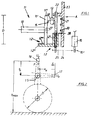
- FIG. 1 shows a winding support tree 11, which consists of a tree axis 10, at the ends of which a side window 11 'is fastened in a conventional manner.
- a winding support tree 11 is provided by the winding machine with a winding in which a large number of threads, for example from a creel, is wound between the side windows 11 ′ onto the tree axis 10.
- the winding support tree 11 must be lifted from the floor position shown in FIG. 1 into a clamping position 15, which is characterized by the longitudinal axis of two aligned clamping shafts 13 of the winding machine. With these clamping shafts, the winding support tree is held up and driven in order to wind up the large number of threads.
- a lifting device 12 which essentially consists of a motor-driven lifting spindle 22, which is rotatably mounted on a machine frame 23 in a stationary or machine frame manner.
- a drive 16 is provided, the driving force of which is transmitted from a drive wheel 16 'seated on its motor shaft via a force transmission element 24, for example a chain, to a spindle disk 25 which is fixed with the lifting spindle 22.
- a force transmission element 24 for example a chain
- This lifting device 12 consists essentially of a threaded sleeve 12 'comprising the lifting spindle 22' and a support arm 12 '', onto which a side window 11 'of the winding support beam 11 has been rolled, with retaining strips 12''' preventing the winding support beam 11 from rolling down unintentionally when lifting.
- the drive 16 of the lifting device 12 is switched off and each clamping shaft 13 can engage in a conical recess 27 of the winding support tree 11, so that the latter is tensioned thereby. So that the side windows 11 'are released from the lifting device 12, the drive 16 can be switched off in such a way that the winding support beam 11 is stopped slightly below the clamping position 15, so that cone surfaces 13' present on the clamping shafts 13 'in cooperation with corresponding cone surfaces of the winding support beam 11 cause its lifting into the exact clamping position 15. It is then not necessary to shut down the lifting device 12 in a controlled manner, which is advantageous since it then does not have to be moved up again when it is used to remove the wound winding support tree 11.
- the lifting devices 12 have to move up differently when lifting the winding support tree 11 if the diameter D of the side disks 11 'is different.
- Smaller and larger winding support trees 11 differ in terms of their side window diameter D in the range from 250 to 1400 mm. Accordingly, there are stroke differences of 575 mm, to which the lifting devices 12 of the winding machine must be set up.
- Fig. 1 shows a proximity switch 20, which is attached to the machine frame 23 and cooperates with a known contactor 28 of the lifting device 12, which is attached to the sleeve 12 'in such a way that it passes in the vicinity of the proximity switch 20 when the lifting device 12 is raised. If the position of the proximity switch 20 is selected so that the contactor 28 is precisely in Switching proximity to the proximity switch 20, when the winding support tree 11 is in its clamping position 15, a switching signal of the proximity switch 20 can be used to switch off the drive 16.
- proximity switches 21 can be used.
- the number of proximity switches is determined in accordance with the different gradations of the diameters of the side disks 11 ′ of different winding support trees 11 that are provided in practical operation. For example, a total of three proximity switches 20, 21 are shown. In fact, their number can correspond to the actual number of gradations of the practically used side disc diameter.
- the proximity switches 20, 21 can also be adjustable on the frame 23, as is indicated by the double arrows assigned to the proximity switches 20, 21. This allows an exact adjustment to be achieved, but also an adaptation of a small number of proximity switches to a larger number of different diameters D of side plates 11 '.
- the procedure can be such that only one of the proximity switches 20, 21 is able to switch off the drive 16, a selection being made before the lifting device 12 is started up.
- the selection of a proximity switch, eg 20, can be done with a selector switch that has as many selector positions as there are proximity switches.
- only the selected proximity switch, for example 20, is armed or activated within the control device (not shown) for switching off the drive 16.
- the latter can be automated, for example with a measuring device which detects the diameter D of the side window 11 'by detecting the position of the edge 11''or the outer circumference, in particular its highest place.
- the detection can take place in a variety of ways, for example by automated mechanical scanning, but expediently by an optoelectronic measuring device, which carries out a measuring cycle for scanning the edge 11 ′′ of the winding support tree 11 when the drive 16 of the lifting device 12 is switched on before it becomes effective and accordingly selects the appropriate proximity switch 20, 21.
- the above-described methods can also be used if proximity switches 20, 21 are not used, but if the stroke of the lifting devices 12 is measured continuously with an incremental encoder.
- the maximum possible measuring path, cf. e.g. in FIG. 2 y max is assigned a number of increments which are large enough to be able to detect the position of the winding support tree precisely enough with regard to the positioning in the clamping position 15.
- programming to predetermined incremental values is carried out in the control device which carries out the measurement of the stroke, for which purpose, for example, a self-programmable controller is used. The programming is carried out in such a way that different side disc diameters D are assigned those incremental numbers which ensure that the winding support tree 11 has reached the desired clamping position 15.
- FIG. 2 explains a special method in which the position of the winding support tree 11 is measured.
- a distance sensor 17 which is oriented horizontally and determines a measured value x.
- a distance meter 18 which is arranged vertically and provides a measured value y.
- the sensors 17, 18 are arranged at right angles to one another and their measuring ranges overlap in the area of the clamping position 15 of the winding support beam 11. Since the distance meter 17 is arranged vertically above the winding support beam 11, it always delivers a measured value y, while the horizontally measuring distance measurement device 17 indicates a measured value ⁇ before lifting the winding support tree 11. Only when the tree axis 10 reaches the measuring range of the distance meter 17 does it determine a measured value of approximately x e . This value has a maximum when the tree axis 10 has reached the clamping position 15 exactly.
- the clamping position 15 is exactly reached if the measured values x e and y e are identical.
- the ratio of these measurements is 1: 1. It can also be different if, for example, the distances of the distance meters 17, 18 from the clamping position 15 are different for structural reasons, or if the distance meters 17, 18 cannot be arranged at right angles to one another for structural reasons.
Landscapes
- Engineering & Computer Science (AREA)
- Textile Engineering (AREA)
- Control And Safety Of Cranes (AREA)
- Warping, Beaming, Or Leasing (AREA)
- Load-Engaging Elements For Cranes (AREA)
Applications Claiming Priority (2)
| Application Number | Priority Date | Filing Date | Title |
|---|---|---|---|
| DE4429482A DE4429482A1 (de) | 1994-08-19 | 1994-08-19 | Verfahren zum Einspannen eines Wickeltragbaums |
| DE4429482 | 1994-08-19 |
Publications (3)
| Publication Number | Publication Date |
|---|---|
| EP0697359A2 true EP0697359A2 (fr) | 1996-02-21 |
| EP0697359A3 EP0697359A3 (fr) | 1997-02-05 |
| EP0697359B1 EP0697359B1 (fr) | 2000-03-22 |
Family
ID=6526112
Family Applications (1)
| Application Number | Title | Priority Date | Filing Date |
|---|---|---|---|
| EP95112283A Expired - Lifetime EP0697359B1 (fr) | 1994-08-19 | 1995-08-04 | Procédé de serrage d'un arbre porte-bobine |
Country Status (3)
| Country | Link |
|---|---|
| EP (1) | EP0697359B1 (fr) |
| DE (2) | DE4429482A1 (fr) |
| ES (1) | ES2146272T3 (fr) |
Cited By (1)
| Publication number | Priority date | Publication date | Assignee | Title |
|---|---|---|---|---|
| US6176670B1 (en) * | 1999-04-21 | 2001-01-23 | Eastman Kodak Company | Roll handling and transport assemblage |
Families Citing this family (2)
| Publication number | Priority date | Publication date | Assignee | Title |
|---|---|---|---|---|
| DE102005002532A1 (de) * | 2005-01-14 | 2006-07-27 | E.C.H. Will Gmbh | Vorrichtung und Verfahren zum automatisierten und zeitgleichen Bereitstellen und Wechseln von mindestens zwei Rollen aus Papierbahnen oder dergleichen für einen nachgeordneten Formatschneider |
| DE102005008168A1 (de) * | 2005-02-22 | 2006-08-31 | Man Roland Druckmaschinen Ag | Rollenwechsler einer Rollendruckmaschine |
Citations (1)
| Publication number | Priority date | Publication date | Assignee | Title |
|---|---|---|---|---|
| DE3436186A1 (de) | 1984-10-03 | 1986-07-10 | Hacoba Textilmaschinen Gmbh & Co Kg, 5600 Wuppertal | Verfahren und vorrichtung zum lagerichtigen einspannen eines wickeltragbaumes |
Family Cites Families (17)
| Publication number | Priority date | Publication date | Assignee | Title |
|---|---|---|---|---|
| CH446249A (de) * | 1965-11-02 | 1967-11-15 | Benninger Ag Maschf | Schlichtmaschine |
| DE1266094B (de) * | 1966-08-18 | 1968-04-11 | Demag Ag | Einrichtung zur automatischen Zentrierung eines Metallband-Bundes zum Dorn einer Haspelstation |
| DE1574327A1 (de) * | 1967-04-14 | 1971-07-01 | Demag Ag | Einrichtung zur automatischen Zentrierung eines Metallband-Bundes zum Dorn einer Haspelstation |
| DE1574328A1 (de) * | 1967-04-14 | 1971-06-16 | Demag Ag | Einrichtung zur automatischen Zentrierung eines Metallband-Bundes zum Dorn einer Haspelstation |
| AT277124B (de) * | 1967-11-06 | 1969-12-10 | Voest Ag | Vorrichtung zum Aufbringen von Bunden auf eine Abwickelhaspel |
| GB1260829A (en) * | 1969-02-21 | 1972-01-19 | Hitachi Ltd | Method and apparatus for automatically aligning a coil |
| DE2136791B2 (de) * | 1971-07-23 | 1973-05-03 | Ungerer Geb. Dollinger, Irma, 7530 Pforzheim | Vorrichtung zum beschicken eines abwickelhaspels |
| DE2450757C3 (de) * | 1974-10-25 | 1981-11-26 | Hacoba Textilmaschinen Gmbh & Co Kg, 5600 Wuppertal | Verfahren und Vorrichtung zum lagerichtigen Einspannen eines mit Seitenscheiben versehenen Wickeltragbaumes in eine Maschine zum Wickeln von Gewebebahnen oder einer Vielzahl von Fäden |
| AT368913B (de) * | 1981-03-19 | 1982-11-25 | Voest Alpine Ag | Vorrichtung zum ausrichten eines blechbundes gegenueber einem haspel |
| SE429583B (sv) * | 1982-09-14 | 1983-09-12 | Lidkoepings Mekaniska Verkstad | Sett att bestemma leget av mittpunkten pa ett cirkulert foremal |
| DE8501277U1 (de) * | 1985-01-19 | 1988-11-17 | Niepmann Traylift Transportsysteme GmbH & Co KG, 5820 Gevelsberg | Vorrichtung zum Entladen einzelner Bobinen von einer Unterlage |
| JPS61243753A (ja) * | 1985-04-22 | 1986-10-30 | Fuji Photo Film Co Ltd | コイルセンタリング装置 |
| JPS62215451A (ja) * | 1986-03-14 | 1987-09-22 | Yaskawa Electric Mfg Co Ltd | コイル装入装置 |
| FR2598395B1 (fr) * | 1986-05-09 | 1990-01-19 | Monomatic Sa | Dispositif de chargement automatique de bobines dans des machines a derouler |
| DE3822572A1 (de) * | 1988-07-04 | 1990-02-22 | Kleinewefers Gmbh | Rollen-abwickelvorrichtung, insbesondere fuer eine druckmaschine |
| DE4037671A1 (de) * | 1990-11-27 | 1992-06-04 | Sundwiger Eisen Maschinen | Positioniervorrichtung fuer auf eine haspeltrommel aufzusteckende bunde, insbesondere aus metallband |
| US5308217A (en) * | 1992-07-20 | 1994-05-03 | Automatic Handling, Inc. | Roll chucking apparatus |
-
1994
- 1994-08-19 DE DE4429482A patent/DE4429482A1/de not_active Withdrawn
-
1995
- 1995-08-04 ES ES95112283T patent/ES2146272T3/es not_active Expired - Lifetime
- 1995-08-04 DE DE59508034T patent/DE59508034D1/de not_active Expired - Fee Related
- 1995-08-04 EP EP95112283A patent/EP0697359B1/fr not_active Expired - Lifetime
Patent Citations (1)
| Publication number | Priority date | Publication date | Assignee | Title |
|---|---|---|---|---|
| DE3436186A1 (de) | 1984-10-03 | 1986-07-10 | Hacoba Textilmaschinen Gmbh & Co Kg, 5600 Wuppertal | Verfahren und vorrichtung zum lagerichtigen einspannen eines wickeltragbaumes |
Cited By (1)
| Publication number | Priority date | Publication date | Assignee | Title |
|---|---|---|---|---|
| US6176670B1 (en) * | 1999-04-21 | 2001-01-23 | Eastman Kodak Company | Roll handling and transport assemblage |
Also Published As
| Publication number | Publication date |
|---|---|
| EP0697359A3 (fr) | 1997-02-05 |
| DE59508034D1 (de) | 2000-04-27 |
| ES2146272T3 (es) | 2000-08-01 |
| DE4429482A1 (de) | 1996-02-22 |
| EP0697359B1 (fr) | 2000-03-22 |
Similar Documents
| Publication | Publication Date | Title |
|---|---|---|
| EP1225139B1 (fr) | Dispositif de retournement | |
| DE3623481C2 (de) | Schraubvorrichtung für selbstschneidende Schrauben | |
| EP0134819A1 (fr) | Pince à moteur électrique pour la commande du serrage | |
| EP0384988A2 (fr) | Dispositif de déroulage pour bobine de bande | |
| DE102006018428A1 (de) | Verfahren und Vorrichtung zum Verlegen von langgestrecktem Wickelgut | |
| DE10223484B4 (de) | Verfahren und Spulmaschine zum Aufwickeln eines kontinuierlich zulaufenden Fadens auf eine Hülse zu einer Spule | |
| DE69232637T2 (de) | Transformatorwickelvorrichtung zum Aufwickeln von drahtförmigem Material auf Spulenkörpern mit korrektem Zählen der Anzahl von Umwicklungen und mit Ermöglichung von Hochgeschindigkeitswickeln | |
| DE2817605A1 (de) | Geraet zum aufwickeln von draht auf spulen | |
| DE2626801C3 (de) | Einrichtung zum Messen der Radioaktivität der Inhalte einer Vielzahl länglicher Probenbehälter | |
| DE19721272A1 (de) | Elektrische Preßvorrichtung | |
| EP0697359B1 (fr) | Procédé de serrage d'un arbre porte-bobine | |
| EP0467091B1 (fr) | Dispositif pour visser des bouchons à vis sur des récipients avec vérification du vissage | |
| DE69020692T2 (de) | Geräte und Verfahren zur Hakenmarkierung und Erkennung in elektrischen Motoren. | |
| EP1245705A2 (fr) | Procédé et dispositif d'optimisation de la vitesse de déroulage sur un cantre | |
| DE3105491C2 (de) | Lebensdauer-Prüfvorrichtung für elektromechanische Bauelemente, wie insbesondere Kraftfahrzeugschalter aller Art | |
| DE3811437C2 (fr) | ||
| DE2948087A1 (de) | Keilriemenmessmaschine | |
| DE3833467C2 (fr) | ||
| DE10238271B4 (de) | Verfahren und Vorrichtung zum zentrierten Spannen eines Kraftfahrzeugrades auf eine Hauptwelle einer Radauswuchtmaschine | |
| DE3735557C1 (de) | Stellvorrichtung fuer einen Spannkopf zum axialen Einspannen von Wickelhuelsen | |
| EP0148127B1 (fr) | Dispositif de positionnement et de mise sous tension de l'ouvrage sur une machine à broder | |
| DE3621794A1 (de) | Verfahren und vorrichtung zur ablage eines faserbandes in einer spinnkanne bei einer spinnereivorbereitungsmaschine, insbesondere einer strecke | |
| DE2904877C2 (de) | Selbsttätig kontrollierende Einrichtung zum Messen von Drehmomenten an mechanischen Verbindungselementen | |
| DE102019104570A1 (de) | Verfahren und Messvorrichtung zur Funktionsprüfung einer Flügelchangierung | |
| DE3438178C2 (fr) |
Legal Events
| Date | Code | Title | Description |
|---|---|---|---|
| PUAI | Public reference made under article 153(3) epc to a published international application that has entered the european phase |
Free format text: ORIGINAL CODE: 0009012 |
|
| AK | Designated contracting states |
Kind code of ref document: A2 Designated state(s): CH DE ES FR GB IT LI |
|
| PUAL | Search report despatched |
Free format text: ORIGINAL CODE: 0009013 |
|
| AK | Designated contracting states |
Kind code of ref document: A3 Designated state(s): CH DE ES FR GB IT LI |
|
| 17P | Request for examination filed |
Effective date: 19970415 |
|
| GRAG | Despatch of communication of intention to grant |
Free format text: ORIGINAL CODE: EPIDOS AGRA |
|
| 17Q | First examination report despatched |
Effective date: 19990618 |
|
| GRAG | Despatch of communication of intention to grant |
Free format text: ORIGINAL CODE: EPIDOS AGRA |
|
| GRAH | Despatch of communication of intention to grant a patent |
Free format text: ORIGINAL CODE: EPIDOS IGRA |
|
| GRAH | Despatch of communication of intention to grant a patent |
Free format text: ORIGINAL CODE: EPIDOS IGRA |
|
| GRAA | (expected) grant |
Free format text: ORIGINAL CODE: 0009210 |
|
| AK | Designated contracting states |
Kind code of ref document: B1 Designated state(s): CH DE ES FR GB IT LI |
|
| PG25 | Lapsed in a contracting state [announced via postgrant information from national office to epo] |
Ref country code: GB Free format text: LAPSE BECAUSE OF FAILURE TO SUBMIT A TRANSLATION OF THE DESCRIPTION OR TO PAY THE FEE WITHIN THE PRESCRIBED TIME-LIMIT Effective date: 20000322 |
|
| REG | Reference to a national code |
Ref country code: CH Ref legal event code: NV Representative=s name: E. BLUM & CO. PATENTANWAELTE Ref country code: CH Ref legal event code: EP |
|
| REF | Corresponds to: |
Ref document number: 59508034 Country of ref document: DE Date of ref document: 20000427 |
|
| ITF | It: translation for a ep patent filed | ||
| ET | Fr: translation filed | ||
| REG | Reference to a national code |
Ref country code: ES Ref legal event code: FG2A Ref document number: 2146272 Country of ref document: ES Kind code of ref document: T3 |
|
| PGFP | Annual fee paid to national office [announced via postgrant information from national office to epo] |
Ref country code: ES Payment date: 20000807 Year of fee payment: 6 |
|
| PGFP | Annual fee paid to national office [announced via postgrant information from national office to epo] |
Ref country code: FR Payment date: 20000828 Year of fee payment: 6 |
|
| GBV | Gb: ep patent (uk) treated as always having been void in accordance with gb section 77(7)/1977 [no translation filed] |
Effective date: 20000322 |
|
| PLBE | No opposition filed within time limit |
Free format text: ORIGINAL CODE: 0009261 |
|
| STAA | Information on the status of an ep patent application or granted ep patent |
Free format text: STATUS: NO OPPOSITION FILED WITHIN TIME LIMIT |
|
| 26N | No opposition filed | ||
| PG25 | Lapsed in a contracting state [announced via postgrant information from national office to epo] |
Ref country code: ES Free format text: LAPSE BECAUSE OF NON-PAYMENT OF DUE FEES Effective date: 20010805 |
|
| PG25 | Lapsed in a contracting state [announced via postgrant information from national office to epo] |
Ref country code: FR Free format text: LAPSE BECAUSE OF NON-PAYMENT OF DUE FEES Effective date: 20020430 |
|
| REG | Reference to a national code |
Ref country code: FR Ref legal event code: ST |
|
| REG | Reference to a national code |
Ref country code: ES Ref legal event code: FD2A Effective date: 20020911 |
|
| REG | Reference to a national code |
Ref country code: CH Ref legal event code: PUE Owner name: MOENUS TEXTILMASCHINEN GMBH Free format text: SUCKER-MUELLER-HACOBA GMBH & CO.#KREFELDER STRASSE 690#D-41066 MOENCHENGLADBACH (DE) -TRANSFER TO- MOENUS TEXTILMASCHINEN GMBH#HEINRICH-HERTZ-STRASSE 28#07552 GERA (DE) |
|
| PGFP | Annual fee paid to national office [announced via postgrant information from national office to epo] |
Ref country code: CH Payment date: 20050831 Year of fee payment: 11 |
|
| PGFP | Annual fee paid to national office [announced via postgrant information from national office to epo] |
Ref country code: DE Payment date: 20050915 Year of fee payment: 11 |
|
| PG25 | Lapsed in a contracting state [announced via postgrant information from national office to epo] |
Ref country code: LI Free format text: LAPSE BECAUSE OF NON-PAYMENT OF DUE FEES Effective date: 20060831 Ref country code: CH Free format text: LAPSE BECAUSE OF NON-PAYMENT OF DUE FEES Effective date: 20060831 |
|
| PG25 | Lapsed in a contracting state [announced via postgrant information from national office to epo] |
Ref country code: DE Free format text: LAPSE BECAUSE OF NON-PAYMENT OF DUE FEES Effective date: 20070301 |
|
| REG | Reference to a national code |
Ref country code: CH Ref legal event code: PL |
|
| PG25 | Lapsed in a contracting state [announced via postgrant information from national office to epo] |
Ref country code: IT Free format text: LAPSE BECAUSE OF NON-PAYMENT OF DUE FEES Effective date: 20070804 |
|
| PGFP | Annual fee paid to national office [announced via postgrant information from national office to epo] |
Ref country code: IT Payment date: 20080826 Year of fee payment: 14 |
|
| PGRI | Patent reinstated in contracting state [announced from national office to epo] |
Ref country code: IT Effective date: 20110616 |
|
| PGRI | Patent reinstated in contracting state [announced from national office to epo] |
Ref country code: IT Effective date: 20110616 |