EP0695017A2 - Batterieanschlussvorrichtung für Rechner und Verfahren zum Umschalten von Batterien - Google Patents
Batterieanschlussvorrichtung für Rechner und Verfahren zum Umschalten von Batterien Download PDFInfo
- Publication number
- EP0695017A2 EP0695017A2 EP95305184A EP95305184A EP0695017A2 EP 0695017 A2 EP0695017 A2 EP 0695017A2 EP 95305184 A EP95305184 A EP 95305184A EP 95305184 A EP95305184 A EP 95305184A EP 0695017 A2 EP0695017 A2 EP 0695017A2
- Authority
- EP
- European Patent Office
- Prior art keywords
- battery
- switching element
- circuit
- diode
- batteries
- Prior art date
- Legal status (The legal status is an assumption and is not a legal conclusion. Google has not performed a legal analysis and makes no representation as to the accuracy of the status listed.)
- Withdrawn
Links
Images


Classifications
-
- H—ELECTRICITY
- H02—GENERATION; CONVERSION OR DISTRIBUTION OF ELECTRIC POWER
- H02J—CIRCUIT ARRANGEMENTS OR SYSTEMS FOR SUPPLYING OR DISTRIBUTING ELECTRIC POWER; SYSTEMS FOR STORING ELECTRIC ENERGY
- H02J1/00—Circuit arrangements for DC mains or DC distribution networks
- H02J1/10—Parallel operation of DC sources
-
- H02J7/575—
-
- H—ELECTRICITY
- H02—GENERATION; CONVERSION OR DISTRIBUTION OF ELECTRIC POWER
- H02J—CIRCUIT ARRANGEMENTS OR SYSTEMS FOR SUPPLYING OR DISTRIBUTING ELECTRIC POWER; SYSTEMS FOR STORING ELECTRIC ENERGY
- H02J9/00—Circuit arrangements for emergency or stand-by power supply, e.g. for emergency lighting
- H02J9/04—Circuit arrangements for emergency or stand-by power supply, e.g. for emergency lighting in which the distribution system is disconnected from the normal source and connected to a standby source
- H02J9/06—Circuit arrangements for emergency or stand-by power supply, e.g. for emergency lighting in which the distribution system is disconnected from the normal source and connected to a standby source with automatic change-over, e.g. UPS systems
- H02J9/061—Circuit arrangements for emergency or stand-by power supply, e.g. for emergency lighting in which the distribution system is disconnected from the normal source and connected to a standby source with automatic change-over, e.g. UPS systems for DC powered loads
Definitions
- the present invention relates to a battery connecting device for a computer and a method for switching batteries, and more particularly, to a battery connecting device, for a computer, that prevents the power loss that results from the use of a diode and extends a battery operational period, and a method for switching batteries.
- a notebook computer incorporates a battery pack (hereafter referred to as a "battery"), and a user employs the battery to operate the computer in those places where an AC power supply is not available.
- a battery pack hereafter referred to as a "battery”
- a fully charged battery will usually operate it for about three hours. The three hours of operation that a fully charged battery may provide, however, are not always sufficient for a user.
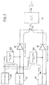
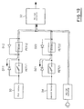
- Fig. 1 is a diagram illustrating a battery connecting device, for a notebook computer in which two batteries are mounted.
- a first battery 10 is connected via a diode 12, which is positioned in the forward direction, to the input terminal of a DC/DC converter 14 that supplies power to a computer.
- a second battery 16 is connected to the input terminal of the DC/DC converter 14 via a diode 18, which is also positioned in the forward direction.
- the first battery 10 and the second battery 16 are OR-connected via the diodes 12 and 18 to the DC/DC converter 14.
- the diode-OR connection prevents the occurrence, because there is a difference in the potentials of the first and second batteries 10 and 16, of a phenomenon wherein a large current flows between the first and the second batteries 10 and 16 and damages the components that are located between the batteries 10 and 16, a wiring pattern, or the batteries 10 and 16 themselves.
- An AC/DC adaptor 20 that converts an AC input into a DC output is connected between the first battery 10 and the diode 12 via a first charge switch 22, and is further connected between the second battery 16 and the diode 18 via a second charge switch 24, thus providing charging routes in addition to a power supply route along which power is supplied to a computer body via the DC/DC converter 14.
- Either the first battery 10 or the second battery 16 can be charged along the charging routes, and power can be supplied to a computer body via either the diode 12 or the diode 18 and the DC/DC converter 14.
- the power that is supplied by a battery transits a diode, and the power loss that results from the use of the diode is not negligible.
- a battery voltage is 10.6 V
- a diode Vf is 0.6 V
- the consumed power of a computer body is 10 W
- the present invention provides a battery connecting device, for a computer, comprising: a plurality of series circuits including a first series circuit, which includes a first circuit and a second circuit, and with said first circuit having a first switching element, which is connectable separably to a first battery at an input terminal, and a first diode, which has an anode connected to the input terminal of said first switching element and a cathode connected to the output terminal of said first switching element, and with said second circuit having a second switching element, which has an input terminal connected to the output terminal of said first switching element and an output terminal connectable to the computer to supply power thereto, and a second diode, which has a cathode connected to the input terminal of said second switching element and an anode connected to the output terminal of said second switching element; a second series circuit, which includes a third circuit and a fourth circuit, and with said third circuit having a third switching element, which is connectable separably to a second battery at an input terminal, and a third di
- the invention advantageously reduces the power loss that is occasioned by a diode and that can extend the battery operational period, and a method for switching batteries and further employs a structure that is simplified by the employment of a common route for supplying power and charging.
- a further embodiment provides a battery connecting device, for a computer system, comprising a plurality of series circuits, connectable to different batteries to supply power to a computer, each of the series circuits being so arranged that drains of paired field-effect transistors that have a diode are connected.
- the present invention also provides a method for switching two batteries, which are connected to paired series circuits of a battery connecting device for a computer system, each of which series circuits includes a first circuit and a second circuit, with the first circuit having a first switching element, which is connectable to a battery at an input terminal, and a first diode, which has an anode connected to the input terminal of the first switching element and a cathode connected to the output terminal of the first switching element, and with the second circuit having a second switching element, which has an input terminal connected to the output terminal of the first switching element and an output terminal connected to a computer body to supply power, and a second diode, which has a cathode connected to the input terminal of the second switching element and an anode connected to the output terminal of the second switching element, comprises steps of: supplying power from one battery to a computer body via the first and the second switching element of one of the series circuits, while supplying power from both of the batteries to the computer body via the first diode; halting
- the battery connecting device is provided a plurality of series circuits, each of which includes the first circuit, which has the first switching element and the first diode, and the second circuit, which has the second switching element and the second diode, has its input terminal connected to the output terminal of the first switching element and the output terminal connected to the computer body to supply power. Since the first switching element and the first diode, and the second switching element and the second diode are connected in parallel to each other, different batteries are connected to the first switching elements by controlling the ON/OFF states of the individual switching elements, and power can be supplied to the computer body without using the first and second diodes. Therefore, the power loss that results from the use of the diodes does not occur and the operating period for the battery can be extended.
- a further embodiment provides a battery connecting device, for a computer, comprising: a plurality of series circuits including a first series circuit, which includes a first circuit and a second circuit, and with said first circuit having a first switching element, which is connectable separably to a first battery at an input terminal, and a first diode, which has an anode connected to the input terminal of said first switching element and a cathode connected to the output terminal of said first switching element, and with said second circuit having a second switching element, which has an input terminal connected to the output terminal of said first switching element and an output terminal connectable to the computer to supply power thereto, and a second diode, which has a cathode connected to the input terminal of said second switching element and an anode connected to the output terminal of said second switching element; a second series circuit, which includes a third circuit and a fourth circuit, and with said third circuit having a third switching element, which is connectable separably to a second battery at an input terminal, and a third diode
- the series circuit in claim 1 can be arranged by connecting the drains of paired field-effect transistors that incorporate diodes that, for example, have their anodes connected to the sources of the transistors and their cathodes connected to the drains.
- the switching of the batteries enables power to be continuously supplied to the computer body.
- the power that is lost by employing an internal diode is so little that it can be disregarded.
- the battery connecting device comprises the first series circuit, which includes both the first circuit, which has the first switching element and the first diode, and the second circuit, which has the second switching element and the second diode, and the second series circuit, which includes both the third circuit, which has the third switching element, and the third diode, and the fourth circuit, which has the fourth switching element and the fourth diode.
- the control means turns on the first and the second switching element, and turns off the third and the fourth switching element in order to supply power from the first battery to the computer body. By doing this, the loss of power that is occasioned by the use of a diode will not occur. Further, when the capacity of the first battery falls to or below a predetermined value, the control means turns off the first switching element, turns on the fourth switching element, turns off the second switching element, and turns on the third switching element, in the named order, in order to supply power from the second battery to the computer body. Since in this manner power is supplied to the computer body in the diode-OR condition, battery switching can be performed without discontinuing the power supply to the computer body.
- the battery connecting device When the first battery is fully charged by a converter, which converts AC voltage into DC voltage, and the charging start condition for the second battery is established, the battery connecting device turns off the first switching element, turns on the fourth switching element, turns off the second switching element, and turns on the third switching element, in the named order, to initiate the charging of the second battery.
- the discharging route can be employed for battery charging. Since the battery connecting device employs the same route both for supplying power and for charging, its structure can be simplified.
- the battery connecting device controls the ON/OFF state of the first and the second switching element so that two or more batteries supply power to the computer body via the first diode. Therefore, when the previous notice for the battery removal is detected, the battery connecting device is in the diode-OR state and this prevents the power supply from being halted when the battery is removed.
- Fig. 1 is a circuit diagram illustrating a conventional battery connecting device for a computer system.
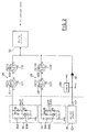
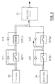
- Fig. 2 is a circuit diagram illustrating a conventional battery connecting device for a computer system according to one embodiment of the present invention.
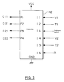
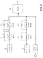
- Fig. 3 is a block diagram illustrating a controller that controls the ON/OFF state of an FET in Fig. 2.
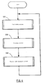
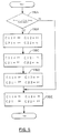
- Fig. 4 is a flowchart showing the charging and discharging routine for this embodiment.
- Fig. 5 is a detailed flowchart for the procedure at step 100 in Fig. 4.
- Fig. 6 is a detailed flowchart for the procedure at step 116 in Fig. 5.
- Fig. 7 is a detailed flowchart for the procedure at step 122 in Fig. 5.
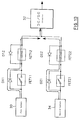
- Fig. 8 is a specific diagram showing how power is supplied from a first battery.
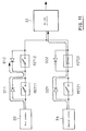
- Fig. 9 is a specific diagram showing how power is supplied via an internal diode D11.
- Fig. 10 is a specific diagram showing a diode-OR state.
- Fig. 11 is a specific diagram showing how power is supplied via an internal diode D21.
- Fig. 12 is a specific diagram showing how power is supplied from a second battery.
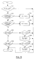
- Fig. 13 is a detailed flowchart for the procedure at step 200 in Fig. 5.
- Fig. 14 is a detailed flowchart for the procedure at step 214 in Fig. 13.
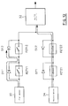
- Fig. 15 is a detailed flowchart for the procedure at step 218 in Fig. 13.
- Fig. 16 is a specific diagram showing how power is supplied from the first battery.
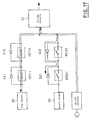
- Fig. 17 is a specific diagram showing how an AC/DC converter is connected to the circuit in Fig. 16.
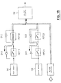
- Fig. 18 is a specific diagram showing that an FET 11 is turned off in the circuit shown in Fig. 17.
- Fig. 19 is a specific diagram showing that an FET 22 is turned on in the circuit shown in Fig. 18.
- Fig. 20 is a specific diagram showing that an FET 12 is turned off in the circuit shown in Fig. 19.
- Fig. 21 is a specific diagram showing that an FET 21 is turned off in the circuit shown in Fig. 20.
- Fig. 22 is a detailed flowchart for the procedure at step 300 in Fig. 5.
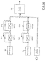
- a battery connecting device for a computer system in this embodiment comprises a first series circuit 26 and a second series circuit 28.
- the first series circuit 26 includes field-effect transistors (each of which will hereafter be referred to as an "FET") 11 and 12 that have their drains D connected together.
- FET field-effect transistors
- a power MOSFET can be used instead of an FET.
- the second series circuit 28, as well as the first series circuit 26, includes FETs 21 and 22 that have their drains D connected together.
- the FETs 11, 12, 21, and 22 incorporate internal diodes D11, D12, D21, D22, respectively, that have their cathodes connected to the respective drains D and their anodes connected to the respective sources S.
- a battery pack (battery) storage unit which employs as a cover a keyboard that is freely opened and closed, may be provided in a notebook computer body for this embodiment.
- the source S of the FET 11 is connectable to a first battery pack 30, which is arranged so as to be removable from the battery pack storage unit within the computer.
- the source S of the FET 12 is connected to the input terminal of a DC/DC converter 32, which supplies power to the computer body.
- a keyboard switch for detecting the open/closed state of the keyboard is also provided in the computer body.
- the source S of the FET 21 is connected to a second battery pack 34, which is so loaded that it is removable from the notebook computer body.
- the source S of the FET 22 is connected to the input terminal of the DC/DC converter 32.
- first battery pack 30 In the first battery pack 30 are provided a first battery cell 30A, resistors R1, R2, and R3, and a thermistor 30B that monitors the temperature of the first battery cell 30A, i.e., the temperature of the first battery pack 30.
- a battery temperature T1 is obtained by monitoring the voltage between the resistor R1 and the thermistor 30B, and a battery voltage V1 is read by monitoring the voltage between the resistors R2 and R3.
- NiMH, etc. can be used as a battery cell.
- the arrangement of the second battery pack 34 is identical to that of the first battery pack 30.
- a second battery cell 34A is provided in the second battery pack 34.
- resistors R4, R5, and R6, and a thermistor 34B that detects the temperature of the second battery cell 34A, i.e., the temperature of the second battery pack 34.
- a battery temperature T2 and a battery voltage V2 are respectively obtained by monitoring the voltage between the resistor R4 and the thermistor 34B and the voltage between the resistors R5 and R6.
- An AC/DC adaptor 36 that converts an AC (alternate current) into a DC (direct current) is connected to the input terminal of the DC/DC converter 32 via a connector (not shown), which is provided on the side of the computer body, and a diode 40, which is incorporated in the computer body.
- the AC/DC adaptor 36 can be removed from the computer body by detaching it from the connector.
- the anode of the diode 40 is connected to a detection circuit 38 that ascertains whether or not the AC/DC adaptor 36 is connected.
- the detection circuit 38 When the AC/DC adaptor 36 is connected to the computer system, the detection circuit 38 outputs a high level signal A. When the AC/DC adaptor is removed from the computer system, the detection circuit 38 outputs a low level signal A.
- Fig. 3 is a diagram showing a controller 42 that controls the switching of the FETs 11 through 22.
- Output pins P1, P2, P3 and P4 are connected to the gates G of the individual FETs to input control signals C11, C12, C21, and C22, respectively.
- Input pins I1 and I2 are so connected that, respectively, they receive the battery voltage V1 and the battery temperature T1.
- Input pins I4 and I5 are so connected that, respectively, they receive the battery voltage V2 and the battery temperature T2.
- An input pin I3 is connected to the keyboard switch that serves as a detection means and detects a previous notice for battery removal, and an input pin I6 is so connected that it receives the signal A from the detection circuit 38.
- the keyboard switch is turned on or off in response to the open or closed state of the keyboard.
- a switch that is turned on or off in response to the opening or closing the cover may be used instead of the keyboard switch.
- the controller 42 is connected to a DC power source VCC, and a GND pin is grounded.
- Fig. 4 is a flowchart showing the control routine for this embodiment.
- a discharging process for a battery pack is performed to supply power from the battery pack to the computer.
- a charging process for the battery pack is performed, and at step 300, a process that is initiated when a keyboard is opened, i.e., a process for giving a notice that a battery is to be removed, is performed.
- Fig. 5 is a detailed flowchart showing the discharging process for a battery pack at step 100.
- a check is performed to determine whether or not the AC/DC adaptor 36 is connected to the computer system. When the AC/DC adaptor 36 is connected, either a charging process is to be performed, or the computer is being powered by the AC/DC adaptor. The routine is thereafter terminated.
- step 110 When, at step 110, the AC/DC adaptor 36 is not connected, one of the batteries is discharged, a procedure which will be described later, and when the capacity of this battery falls to or below a predetermined value, the other battery will be discharged.
- a check is performed to determine whether or not the battery voltage V1 of the first battery pack 30 is greater than a reference voltage V0, which is equivalent to the operation halt voltage for a battery.
- the reference voltage V0 is employed to halt the battery discharging when the battery voltage V1 is reduced to the reference voltage V0 or lower.
- the discharging is enabled.
- a check is performed to determine whether or not the first battery pack 30 is being discharged. When the first battery pack 30 is being discharged, the routine is terminated. If it is determined that the first battery pack 30 is not discharging, the discharge of the first battery pack 30 is initiated, as will be described later, at step 116.
- a check is then performed at step 118 to determine whether or not the battery voltage V2 of the second battery pack 34 is greater than the reference voltage V0. If the battery voltage V2 is greater than the reference voltage V0, at step 120 a check is performed to determine whether or not the second battery pack 34 is being discharged. If the second battery pack 34 is being discharged, the routine is terminated. If the second battery pack 34 is not being discharged, the discharge of the second battery pack 34 is initiated, at step 122, as will be described later.
- the battery voltage V2 is equal to or lower than the reference voltage V0, i.e., when the normal discharge of the first battery pack 30 and the second battery pack 34 cannot be performed, it is assumed that the capacities of both batteries are equal to or lower than a predetermined value.
- An LED is switched on to indicate the remaining battery capacities are low and the computer is set to the suspended state and powered down. While the computer is in the suspended state, power is supplied to electronic components, such as a memory and a memory controller, but no power is supplied to a display, etc.
- Fig. 6 is a detailed flowchart for the procedure at step 116.
- a check is performed to determine whether or not the second battery pack 34 is being discharged. If the second battery pack 34 is not being discharged, it is assumed that the second battery pack 34 is not in use while the first battery pack 30 is in use.
- the controller 42 outputs control signals C11, C12, C21, and C22 for turning on the FETs 11 and 12 and for turning off the FETs 21 and 22 (Fig. 8). Then, the discharge of the first battery pack 30 is performed to supply power to the computer body.
- step 116A the second battery pack 34 is being discharged, the FETs 11 and 12 are off and the FETs 21 and 22 are on (Fig. 12).
- step 116B the FET 21 is then turned off.
- the FET 12 is turned on.
- the FET 22 is turned off.
- the supply of power from the second battery pack 34 is halted by the internal diode D22 and only power from the first battery pack 30 is supplied.
- the FET 11 is turned on. Then, power from the first battery pack 30 is supplied via the source-drain of the FET 11 and the drain-source of the FET 12, and does not pass through the internal diode D11 of the FET 11 and the internal diode D12 of the FET 12.
- Fig. 7 is a detailed flowchart for the procedure at step 122.
- a check is performed to determine whether or not the first battery pack 30 is being discharged. If the first battery pack 30 is not being discharged, at step 122E the FETs 11 and 12 are turned on and the FETs 21 and 22 are turned off (Fig. 12). Thus, power from the second battery pack 34 is supplied to the computer body without passing through the internal diodes D21 and D22, and the power loss that results from the use of the internal diodes does not occur.
- step 122A the first battery pack 30 is being discharged
- the FET 11 is turned off at step 122B
- the FET 22 is turned on at step 122C (set to the diode-OR state)
- the FET 12 is turned off at step 122D
- the FET 21 is turned on at step 122E.
- the control signals from the controller 42 at this period are shown at steps 122B through 122E in Fig. 7.
- the battery switching that is performed in consonance with the flowchart in Fig. 7 is illustrated in Figs. 8 through 12.
- the state where the first battery pack 30 is being discharged is shown in Fig. 8.
- Figs. 9 through 12 correspond to steps 122B through 122E, respectively.
- Fig. 13 is a detailed flowchart for the procedure at step 200.
- a check is performed to determine whether or not the AC/DC adaptor 36 is connected. When the AC/DC adaptor 36 is not connected, charging cannot be performed. The routine is therefore terminated.
- step 210 the AC/DC adaptor 36 is connected, one of the batteries is charged, as will be described later. When this battery is fully charged, the charging of the other battery is begun.
- a check is performed to determine whether or not the charging start condition for the second battery pack 34 is established.
- the battery temperature must be within a predetermined range (for example, 5°C ⁇ battery temperature ⁇ 43°C) and the battery voltage is equal to or lower than a battery charge start voltage (which may be the same as the reference voltage V0). When these requirements are satisfied, the charging start condition is established.
- the charging is begun at step 214, as will be described later.
- the charging start condition for the second battery pack 34 is not established, at step 216, a check is performed, by referring to the above described requirements, to determine whether or not the charging start condition for the first battery pack 30 is established.
- the charging is begun at step 218, as will be described later.
- a check is performed to determine whether or not the second battery pack 34 is being charged. If the second battery pack 34 is being charged, a check is performed at step 222 to determine whether or not the second battery pack 34 has been fully charged. A measured increase in the battery temperature since the beginning of the charging, or the attainment of a specified battery temperature is employed for this determination. When the battery temperature has risen a predetermined number of degrees (e.g., 22°C) or more since the beginning of the charging, or when the battery temperature reaches a specific value (e.g., 60°C), the second battery pack 34 is determined to have been fully charged.
- a predetermined number of degrees e.g. 22°C
- a specific value e.g. 60°C
- the control signal C21 is output to the gate and the FET 21 is turned off to halt the charging of the second battery pack 34. If, at step 220, the second battery pack 34 is not being charged, a check is performed at step 226 to determine whether or not the first battery pack 30 is being charged. If the first battery pack 30 is being charged, at step 228 a check is performed, by referring to the above described requirements, to determine whether or not the first battery pack 30 has been fully charged. When the first battery pack 30 has been fully charged, the control signal C11 is output to the gate and the FET 11 is turned off, thus halting the charging of the first battery pack 30.
- Fig. 16 is a diagram showing how power is supplied from the first battery pack 30.
- the AC/DC adaptor 36 is connected to the circuit in this state, and the charging start condition for the first battery pack 30 is established, the charging for the first battery pack 30 is initiated, as is shown in Fig. 17 (step 218).
- the charging for the first battery pack 30 is halted, as is shown in Fig. 18 (step 230).
- Fig. 14 is a detailed flowchart for the procedure at step 214 where the second battery pack 34 is to be charged.
- the charging start condition for the second battery pack 34 is established, the charging of the first battery pack 30 is completed, and the FET 11 is in the off state, the FET 12 is in the on state, the FET 21 is in the off state, and the FET 22 is in the on state (Fig. 18). Therefore, the FET 22 is turned on at step 214A (Fig. 19), the FET 12 is turned off at step 214B (Fig. 20), and the FET 21 is turned on at step 214C (Fig. 21).
- the charging for the second battery pack 34 is then begun. It should be noted that, at steps 214A through 214C in Fig. 16, the states of the FETs are described by the ON/OFF control signals C11 through C22 that are carried to the gates.
- Fig. 15 is a detailed flowchart for the procedure at step 218 where the first battery pack 30 is to be charged.
- the FETs 11, 12, and 21 are in the off state and the FET 22 is in the on state. Therefore, the FET 12 is turned on at step 218A, the FET 22 is turned off at step 218B, and the FET 11 is turned on at step 218C.
- Fig. 22 is a detailed flowchart for the procedure at step 300.
- a check is performed to determine whether or not the keyboard was opened in consonance with a signal from the keyboard switch, i.e., whether or not a previous notice that a battery is to be removed was issued.
- the first battery pack 30 and the second battery pack 34 are set to the diode-OR state with respect to the DC/DC converter 32. More specifically, to supply power from the first battery pack 30, the FET 11 is turned off and the FET 22 is turned on. To supply power from the second battery pack 34, the FET 21 is turned off and the FET 12 is turned on. Even if one of the batteries is removed, power can be supplied from the remaining battery. Although at this period power is to be supplied via the diode, the replacement of a battery can be completed within a short period of period and there is therefore very little power loss.
- step 314 a check is performed to determine whether or not the keyboard has been closed. When the keyboard is closed, the routine is terminated.
- the batteries are connected individually to two series circuits, three or more series circuits may be employed and the batteries may be connected to each of the series circuits.
- the FETs are employed as switching elements, other switching elements, such as transistors or relays, may be employed.
- the issuance of the previous notice for battery removal is detected upon the opening of the keyboard, the issuance of such a previous notice may be detected by determining whether the battery capacity is equal to or lower than a predetermined value.
- the FET employed in this embodiment has a diode which has its anode connected to the source of the FET and its cathode connected to the drain
- the present invention is not limited to the thus arranged FET, and an FET where the cathode of a diode is connected to the source may be used.
- the power loss that is caused by diodes can be eliminated and the operating period when using a battery can be extended.
- the operating period for a battery can be extended, and batteries that are being discharged can be switched without halting the power supply when the capacity of one of the batteries is decreased.
- a route for the power supply is a common route that is also used for charging, a battery connecting device that has a simple structure can be provided and batteries that are being charged can be smoothly switched.
- the battery connecting device Since the battery connecting device is in the diode-OR state when a previous notice that indicates a battery is to be removed is detected, the operating period for a battery can be extended, and halting of the power supply, which is ascertained by the removal of a battery, can be prevented.
Landscapes
- Engineering & Computer Science (AREA)
- Power Engineering (AREA)
- Business, Economics & Management (AREA)
- Emergency Management (AREA)
- Charge And Discharge Circuits For Batteries Or The Like (AREA)
- Power Sources (AREA)
Applications Claiming Priority (2)
| Application Number | Priority Date | Filing Date | Title |
|---|---|---|---|
| JP6174387A JP2708374B2 (ja) | 1994-07-26 | 1994-07-26 | コンピュータ用バッテリ接続装置及びバッテリの切換方法 |
| JP174387/94 | 1994-07-26 |
Publications (1)
| Publication Number | Publication Date |
|---|---|
| EP0695017A2 true EP0695017A2 (de) | 1996-01-31 |
Family
ID=15977726
Family Applications (1)
| Application Number | Title | Priority Date | Filing Date |
|---|---|---|---|
| EP95305184A Withdrawn EP0695017A2 (de) | 1994-07-26 | 1995-07-25 | Batterieanschlussvorrichtung für Rechner und Verfahren zum Umschalten von Batterien |
Country Status (3)
| Country | Link |
|---|---|
| US (1) | US5784626A (de) |
| EP (1) | EP0695017A2 (de) |
| JP (1) | JP2708374B2 (de) |
Cited By (18)
| Publication number | Priority date | Publication date | Assignee | Title |
|---|---|---|---|---|
| EP0736828A3 (de) * | 1995-04-06 | 1997-11-12 | Seiko Epson Corporation | Batteriebetriebenes elektronisches Gerät und Verfahren zur Steuerung der Stromversorgung im Gerät |
| GB2318001A (en) * | 1996-10-07 | 1998-04-08 | Nec Corp | Power supply switching circuit; battery protection |
| EP0800252A3 (de) * | 1996-05-07 | 1999-06-16 | Michael Riedel Transformatorenbau Elektronik GmbH | Unterbrechungsfreie Spannungsversorgungsvorrichtung |
| WO2002067404A1 (en) * | 1999-08-30 | 2002-08-29 | Matsushita Electric Industrial Co., Ltd. | Wireless communication device and method of switching power supply |
| WO2004084374A1 (en) * | 2003-03-18 | 2004-09-30 | Qualcomm Incorporated | Battery management |
| EP1521344A1 (de) * | 2003-09-30 | 2005-04-06 | Freescale Semiconductor, Inc. | Stromversorgungsgerät |
| WO2007145951A3 (en) * | 2006-06-06 | 2008-07-17 | Medtronic Minimed Inc | Method and apparatus for providing backup power to a portable electronic device |
| CN100444496C (zh) * | 2003-03-18 | 2008-12-17 | 高通股份有限公司 | 具有两个电池的电源,供应电流的方法和包括该电源的无线通信装置 |
| FR2926934A1 (fr) * | 2008-01-29 | 2009-07-31 | Saft Groupe Sa | System electronique pour batterie |
| WO2010030782A1 (en) * | 2008-09-12 | 2010-03-18 | Nellcor Puritan Bennett Llc | Low power isolation design for a multiple sourced power bus |
| EP2178196A3 (de) * | 2008-10-17 | 2011-07-13 | Zarlink Semiconductor Limited | Stromversorgungssteuerschaltung, Stromversorgung und Körperimplantat |
| CN101414211B (zh) * | 2007-10-18 | 2012-07-18 | 鸿富锦精密工业(深圳)有限公司 | 电源侦测电路 |
| CN101373395B (zh) * | 2007-08-24 | 2013-01-09 | 鸿富锦精密工业(深圳)有限公司 | 电源报警电路 |
| US8663201B2 (en) | 2005-08-16 | 2014-03-04 | Medtronic Minimed, Inc. | Infusion device |
| CN105281400A (zh) * | 2014-07-03 | 2016-01-27 | 西门子公司 | 用于为电池系统平衡充电状态的装置和方法 |
| WO2016019982A1 (de) * | 2014-08-05 | 2016-02-11 | Vega Grieshaber Kg | Verbindevorrichtung und verfahren zum verbinden |
| WO2017217993A1 (en) * | 2016-06-16 | 2017-12-21 | Thomson Licensing | Method and apparatus for decreasing power consumption in a low power device |
| FR3083935A1 (fr) * | 2018-07-12 | 2020-01-17 | Finsecur | Systeme de commutation d'alimentation entre deux piles electriques |
Families Citing this family (84)
| Publication number | Priority date | Publication date | Assignee | Title |
|---|---|---|---|---|
| US5661634A (en) * | 1993-11-09 | 1997-08-26 | Fujitsu Limited | Information processing system using portable terminal unit and data communication adapter therefor |
| JP3545129B2 (ja) * | 1996-05-22 | 2004-07-21 | 三洋電機株式会社 | 電子機器の電源制御回路 |
| JPH118939A (ja) * | 1997-06-13 | 1999-01-12 | Nec Corp | 電源回路およびバッテリ制御装置 |
| KR100290988B1 (ko) * | 1997-12-29 | 2001-06-01 | 윤종용 | 멀티유니트배터리팩및이멀티유니트배터리팩을사용하는시스템 |
| SE515882C2 (sv) * | 1998-03-17 | 2001-10-22 | Ericsson Telefon Ab L M | Elektriskt effekthanteringssystem samt radiokommunikationsanordning innefattande ett sådant system |
| KR100415989B1 (ko) | 1998-07-11 | 2004-05-20 | 삼성전자주식회사 | 컴퓨터고유배터리팩또는일반배터리를사용할수있는휴대형컴퓨터 |
| JP2000112577A (ja) * | 1998-09-24 | 2000-04-21 | Internatl Business Mach Corp <Ibm> | バッテリ切換回路 |
| EP1014535A3 (de) * | 1998-12-23 | 2001-02-28 | Alcatel | Unterbrechungsfreies Stromversorgungssystem |
| DE19913131B4 (de) * | 1999-03-23 | 2004-07-22 | Siemens Ag | Stromversorgungssystem mit zwei Batterien unterschiedlicher Spannung |
| US6153947A (en) * | 1999-07-06 | 2000-11-28 | Lucent Technologies Inc. | Dual feed hot swap battery plant controller for power supplies |
| US6687839B1 (en) * | 2000-05-31 | 2004-02-03 | Palmone, Inc. | Method and apparatus allowing a battery to regain charge in a handheld device without an applied external charge while still supplying power selected designated components |
| US6445086B1 (en) | 2000-06-28 | 2002-09-03 | David H. Houston | Electronic power supply for personal computer and method |
| JP4567153B2 (ja) * | 2000-07-07 | 2010-10-20 | 株式会社アイオイ・システム | 二線式遠隔制御システム及び二線式表示装置 |
| JP4777507B2 (ja) * | 2000-09-18 | 2011-09-21 | 富士通株式会社 | 電子機器および処理能力変更指示装置 |
| US7671489B1 (en) * | 2001-01-26 | 2010-03-02 | Sirf Technology, Inc. | Method and apparatus for selectively maintaining circuit power when higher voltages are present |
| US6800962B2 (en) * | 2002-01-16 | 2004-10-05 | Adtran, Inc. | Method and apparatus for forced current sharing in diode-connected redundant power supplies |
| JP3854175B2 (ja) * | 2002-03-01 | 2006-12-06 | インターナショナル・ビジネス・マシーンズ・コーポレーション | 電気機器、コンピュータ装置、コントローラ、電池切換方法、およびプログラム |
| AU2003285140A1 (en) * | 2002-11-01 | 2004-06-07 | Rudy Kraus | Apparatus for providing high quality power |
| JP2004187467A (ja) * | 2002-12-06 | 2004-07-02 | Century Corp | 携帯電話用の臨時電源 |
| JP4073880B2 (ja) * | 2003-03-31 | 2008-04-09 | セイコーインスツル株式会社 | 電子機器 |
| KR100702362B1 (ko) * | 2004-10-06 | 2007-04-02 | 삼성전자주식회사 | 안정적인 시스템 종료를 위한 전원 공급 회로 및 방법 |
| US7345455B2 (en) * | 2004-11-18 | 2008-03-18 | International Business Machines Corporation | Staggered backup battery charging system |
| US20070106913A1 (en) * | 2005-11-07 | 2007-05-10 | Lewis Jonathan F | Implementing power over network data link for systems utilizing multiple power sources |
| US7589497B2 (en) * | 2006-02-28 | 2009-09-15 | Dell Products L.P. | Field expandable battery systems and related methods |
| JP5277595B2 (ja) * | 2006-09-26 | 2013-08-28 | セイコーエプソン株式会社 | 回路を含む装置、デバイス、送受信システム、および、制御方法 |
| JP5361176B2 (ja) * | 2006-12-13 | 2013-12-04 | 株式会社半導体エネルギー研究所 | 半導体装置 |
| KR20100017380A (ko) * | 2007-04-27 | 2010-02-16 | 산요덴키가부시키가이샤 | 전원 장치 및 전동 차량 |
| DE102007039835A1 (de) * | 2007-08-23 | 2009-02-26 | Robert Bosch Gmbh | Steuergerät und Verfahren zur Ansteuerung von Personenschutzmitteln für ein Fahrzeug |
| US7945798B2 (en) * | 2007-10-03 | 2011-05-17 | Lenovo (Singapore) Pte. Ltd. | Battery pack for portable computer |
| JP5189343B2 (ja) * | 2007-10-23 | 2013-04-24 | ローム株式会社 | セレクタ回路およびそれを用いた電子機器 |
| CN101436830B (zh) * | 2007-11-15 | 2011-06-08 | 鸿富锦精密工业(深圳)有限公司 | 电源装置及其保护方法 |
| US8212412B1 (en) * | 2007-11-30 | 2012-07-03 | Northern Power Systems Utility Scale, Inc. | Energy storage connection system |
| US7855530B2 (en) * | 2008-02-25 | 2010-12-21 | Stinger Industries, Llc | Battery charging system and method of reducing variation in battery charging cycle count |
| US7800255B2 (en) * | 2008-02-25 | 2010-09-21 | Stinger Industries LLC | Power system for mobile workstation and method |
| US7830668B2 (en) * | 2008-02-25 | 2010-11-09 | Stinger Industries LLC | Power supply unit for mobile workstation and method |
| US8227943B2 (en) * | 2008-02-25 | 2012-07-24 | Lee Melvin Harbin | Power system retrofit kit for mobile workstation and retrofit method |
| US7782607B2 (en) * | 2008-02-25 | 2010-08-24 | Stinger Industries LLC | Mobile workstation having power system with removable battery configured for drop-in engagement therewith |
| US8169191B2 (en) * | 2008-02-25 | 2012-05-01 | Werthman Dean A | System for use in gathering or processing data in a healthcare facility having fleet of mobile workstations |
| US8160727B2 (en) * | 2008-02-25 | 2012-04-17 | Gary Coonan | Mobile workstation control system configured for power system and peripheral device control |
| US8775828B2 (en) * | 2008-02-25 | 2014-07-08 | Gary Coonan | Power control system for mobile workstation and method |
| JP5319236B2 (ja) * | 2008-10-22 | 2013-10-16 | 日立建機株式会社 | 電源装置および作業機械 |
| US8806271B2 (en) * | 2008-12-09 | 2014-08-12 | Samsung Electronics Co., Ltd. | Auxiliary power supply and user device including the same |
| US8546977B2 (en) * | 2009-04-22 | 2013-10-01 | Lsi Corporation | Voltage based switching of a power supply system current |
| TWI369829B (en) * | 2009-06-03 | 2012-08-01 | Well Shin Technology Co Ltd | Portable power-supply devices |
| CN102004538B (zh) * | 2009-08-31 | 2014-03-26 | 鸿富锦精密工业(深圳)有限公司 | 笔记本电脑电源供应电路 |
| EP2485349A4 (de) * | 2009-10-02 | 2017-08-02 | Panasonic Corporation | Leistungsverteilungsvorrichtung und leistungsverteilungssystem damit |
| US20110108538A1 (en) | 2009-11-06 | 2011-05-12 | Rick Gray | Electrically heated garment |
| US20130037531A1 (en) | 2009-11-06 | 2013-02-14 | Rick Gray | Electrically heated garment |
| US8866441B2 (en) * | 2009-11-11 | 2014-10-21 | Atieva, Inc. | Interlock mechanism for a multiple battery pack |
| TW201128906A (en) * | 2010-04-13 | 2011-08-16 | Eneraiser Technology Co Ltd | High-reliability dual power automatic switching loop and isolation device thereof |
| US8737947B2 (en) * | 2010-08-26 | 2014-05-27 | Infineon Technologies Ag | Transponder power supply, a transponder and a method for providing a transponder power supply current |
| JP2012061023A (ja) * | 2010-09-14 | 2012-03-29 | Angel Playing Cards Co Ltd | カード読取り装置およびテーブルゲームシステム |
| US20120153900A1 (en) * | 2010-12-20 | 2012-06-21 | Nexergy, Inc. | Two-way switching regulator |
| US9379558B2 (en) * | 2011-03-08 | 2016-06-28 | Lenovo (Singapore) Pte. Ltd. | Dual rate charger for notebook computer |
| CN103026580B (zh) | 2011-03-29 | 2016-08-03 | 松下知识产权经营株式会社 | 电力控制装置及电力控制方法 |
| US8878390B2 (en) * | 2011-04-22 | 2014-11-04 | David Lee Lorentzen | Adaptor for adding a second power supply unit to a computer system |
| US9071067B2 (en) | 2011-05-12 | 2015-06-30 | Lenovo (Singapore) Pte. Ltd. | Fast battery charging system and method |
| US8772966B1 (en) * | 2011-05-18 | 2014-07-08 | Applied Micro Circuits Corporation | System and method for selecting a power supply source |
| JP2013240267A (ja) * | 2012-04-17 | 2013-11-28 | Panasonic Corp | 電源切換装置および電子機器 |
| CN103403643B (zh) * | 2012-06-27 | 2016-03-02 | 华为终端有限公司 | 充放电管理装置及移动终端 |
| CN103853637A (zh) * | 2012-12-04 | 2014-06-11 | 鸿富锦精密工业(武汉)有限公司 | 开关机测试电路 |
| KR20140072692A (ko) * | 2012-12-05 | 2014-06-13 | 삼성에스디아이 주식회사 | 전력 저장 시스템 및 그 구동 방법 |
| JP5883405B2 (ja) * | 2013-02-20 | 2016-03-15 | レノボ・シンガポール・プライベート・リミテッド | 通電範囲の制御方法および携帯式電子機器 |
| USD808616S1 (en) | 2014-02-28 | 2018-01-30 | Milwaukee Electric Tool Corporation | Single control button for an article of clothing |
| US9735614B2 (en) * | 2014-05-18 | 2017-08-15 | Nxp Usa, Inc. | Supply-switching system |
| US11033059B2 (en) | 2014-11-06 | 2021-06-15 | Milwaukee Electric Tool Corporation | Article of clothing with control button |
| US9843319B2 (en) * | 2015-02-24 | 2017-12-12 | Infineon Technologies Ag | System and method for a fault protection circuit |
| FR3036867B1 (fr) * | 2015-05-29 | 2018-07-27 | IFP Energies Nouvelles | Dispositif d'alimentation d'un recepteur electrique avec commutation entre deux sources de tension continue, et procede d'alimentation mettant en œuvre un tel dispositif |
| US10897145B2 (en) * | 2015-12-29 | 2021-01-19 | Vito Nv | Device and method for the reconfiguration of a rechargeable energy storage device into separate battery connection strings |
| WO2017131710A1 (en) * | 2016-01-28 | 2017-08-03 | Hewlett Packard Enterprise Development Lp | Concurrent alternating-current and direct-current |
| JP6626741B2 (ja) * | 2016-03-01 | 2019-12-25 | 矢崎総業株式会社 | バッテリシステム制御装置 |
| US9991699B2 (en) * | 2016-05-02 | 2018-06-05 | Microsoft Technology Licensing, Llc | Enablement of device power-on with proper assembly |
| DE102016112764B4 (de) * | 2016-07-12 | 2020-08-06 | Lisa Dräxlmaier GmbH | Schnittstellenmodul für ein bordnetz eines kraftfahrzeugs, stromverteiler sowie bordnetz für ein kraftfahrzeug |
| JP6760091B2 (ja) * | 2017-01-11 | 2020-09-23 | 株式会社デンソー | 電源装置及び電源システム |
| DE102017113664A1 (de) * | 2017-06-21 | 2018-12-27 | Schaeffler Technologies AG & Co. KG | Versorgungsschaltung für elektronische Komponenten aus mehreren Spannungspotentialen |
| DE102017221621A1 (de) * | 2017-12-01 | 2019-06-06 | Bayerische Motoren Werke Aktiengesellschaft | Vorrichtung zur redundanten Energieversorgung zumindest eines Verbrauchers eines Kraftfahrzeugs aus einem Bordnetz, Bordnetz sowie Kraftfahrzeug |
| US10432184B1 (en) * | 2018-08-09 | 2019-10-01 | Texas Instruments Incorporated | Channel switchover power multiplexer circuits, and methods of operating the same |
| JP7021661B2 (ja) * | 2019-04-12 | 2022-02-17 | 株式会社デンソー | 電源装置の制御装置 |
| US10723235B1 (en) * | 2019-08-30 | 2020-07-28 | Kitty Hawk Corporation | Flexible battery system for a vehicle |
| US11744298B2 (en) | 2020-12-04 | 2023-09-05 | Milwaukee Electric Tool Corporation | Electrically heated garment with pass-through battery pocket |
| USD1020226S1 (en) | 2021-10-21 | 2024-04-02 | Milwaukee Electric Tool Corporation | Control button for heated garment |
| US11777334B2 (en) * | 2021-11-11 | 2023-10-03 | Beta Air, Llc | System for charging multiple power sources and monitoring diode currents for faults |
| JP7770218B2 (ja) * | 2022-03-16 | 2025-11-14 | 株式会社マキタ | 電気機器 |
| US20240186885A1 (en) * | 2022-12-01 | 2024-06-06 | Rivian Ip Holdings, Llc | Systems and methods for energy delivery |
Family Cites Families (9)
| Publication number | Priority date | Publication date | Assignee | Title |
|---|---|---|---|---|
| US4163935A (en) * | 1975-03-06 | 1979-08-07 | Canon Kabushiki Kaisha | Apparatus for checking a battery voltage |
| US4079303A (en) * | 1976-07-28 | 1978-03-14 | The United States Of America As Represented By The United States Department Of Energy | Charging system and method for multicell storage batteries |
| JPH01288840A (ja) * | 1988-05-16 | 1989-11-21 | Minolta Camera Co Ltd | カメラの電源供給システム |
| JPH0219911A (ja) * | 1988-07-08 | 1990-01-23 | Nec Eng Ltd | 半導体デイスク装置 |
| KR930008260B1 (ko) * | 1989-09-29 | 1993-08-27 | 가부시기가이샤 도시바 | 휴대용 컴퓨터를 위한 지능 전원 시스템 |
| US5057779A (en) * | 1990-04-05 | 1991-10-15 | Motorola, Inc. | Temperature independent voltage monitor for use in a battery operated electronic device |
| JPH04193033A (ja) * | 1990-11-26 | 1992-07-13 | Hitachi Ltd | バッテリシステム |
| US5448719A (en) * | 1992-06-05 | 1995-09-05 | Compaq Computer Corp. | Method and apparatus for maintaining and retrieving live data in a posted write cache in case of power failure |
| JP3477733B2 (ja) * | 1992-09-24 | 2003-12-10 | ソニー株式会社 | 充電装置 |
-
1994
- 1994-07-26 JP JP6174387A patent/JP2708374B2/ja not_active Expired - Fee Related
-
1995
- 1995-07-25 EP EP95305184A patent/EP0695017A2/de not_active Withdrawn
- 1995-07-26 US US08/507,694 patent/US5784626A/en not_active Expired - Fee Related
Non-Patent Citations (1)
| Title |
|---|
| None |
Cited By (31)
| Publication number | Priority date | Publication date | Assignee | Title |
|---|---|---|---|---|
| EP0736828A3 (de) * | 1995-04-06 | 1997-11-12 | Seiko Epson Corporation | Batteriebetriebenes elektronisches Gerät und Verfahren zur Steuerung der Stromversorgung im Gerät |
| EP0800252A3 (de) * | 1996-05-07 | 1999-06-16 | Michael Riedel Transformatorenbau Elektronik GmbH | Unterbrechungsfreie Spannungsversorgungsvorrichtung |
| GB2318001A (en) * | 1996-10-07 | 1998-04-08 | Nec Corp | Power supply switching circuit; battery protection |
| GB2318001B (en) * | 1996-10-07 | 2000-10-11 | Nec Corp | Power supply switching circuit with protection function |
| WO2002067404A1 (en) * | 1999-08-30 | 2002-08-29 | Matsushita Electric Industrial Co., Ltd. | Wireless communication device and method of switching power supply |
| US7734317B2 (en) | 2003-03-18 | 2010-06-08 | Qualcomm Incorporated | Battery management |
| WO2004084374A1 (en) * | 2003-03-18 | 2004-09-30 | Qualcomm Incorporated | Battery management |
| CN100444496C (zh) * | 2003-03-18 | 2008-12-17 | 高通股份有限公司 | 具有两个电池的电源,供应电流的方法和包括该电源的无线通信装置 |
| EP1521344A1 (de) * | 2003-09-30 | 2005-04-06 | Freescale Semiconductor, Inc. | Stromversorgungsgerät |
| WO2005039015A1 (en) * | 2003-09-30 | 2005-04-28 | Freescale Semiconductor, Inc. | Power supply apparatus |
| US7482781B2 (en) | 2003-09-30 | 2009-01-27 | Freescale Semiconductor, Inc. | Controlling power supply between a voltage generator, a load and a rechargeable battery |
| US7737581B2 (en) | 2005-08-16 | 2010-06-15 | Medtronic Minimed, Inc. | Method and apparatus for predicting end of battery life |
| US8663201B2 (en) | 2005-08-16 | 2014-03-04 | Medtronic Minimed, Inc. | Infusion device |
| US8106534B2 (en) | 2005-08-16 | 2012-01-31 | Medtronic Minimed, Inc. | Method and apparatus for predicting end of battery life |
| WO2007145951A3 (en) * | 2006-06-06 | 2008-07-17 | Medtronic Minimed Inc | Method and apparatus for providing backup power to a portable electronic device |
| CN101373395B (zh) * | 2007-08-24 | 2013-01-09 | 鸿富锦精密工业(深圳)有限公司 | 电源报警电路 |
| CN101414211B (zh) * | 2007-10-18 | 2012-07-18 | 鸿富锦精密工业(深圳)有限公司 | 电源侦测电路 |
| US8193773B2 (en) | 2008-01-29 | 2012-06-05 | Saft | Electronic system for a battery |
| FR2926934A1 (fr) * | 2008-01-29 | 2009-07-31 | Saft Groupe Sa | System electronique pour batterie |
| EP2085268A3 (de) * | 2008-01-29 | 2010-09-08 | Saft Groupe S.A. | Elektronisches System für Batterie |
| US7893560B2 (en) | 2008-09-12 | 2011-02-22 | Nellcor Puritan Bennett Llc | Low power isolation design for a multiple sourced power bus |
| WO2010030782A1 (en) * | 2008-09-12 | 2010-03-18 | Nellcor Puritan Bennett Llc | Low power isolation design for a multiple sourced power bus |
| US8145312B2 (en) | 2008-10-17 | 2012-03-27 | Microsemi Semiconductor Limited | Power supply control circuit, power supply and body implant |
| EP2178196A3 (de) * | 2008-10-17 | 2011-07-13 | Zarlink Semiconductor Limited | Stromversorgungssteuerschaltung, Stromversorgung und Körperimplantat |
| CN105281400A (zh) * | 2014-07-03 | 2016-01-27 | 西门子公司 | 用于为电池系统平衡充电状态的装置和方法 |
| US9787107B2 (en) | 2014-07-03 | 2017-10-10 | Siemens Aktiengesellschaft | Apparatus and method for state of charge compensation for a battery system |
| CN105281400B (zh) * | 2014-07-03 | 2018-05-11 | 西门子公司 | 用于为电池系统平衡充电状态的装置和方法 |
| WO2016019982A1 (de) * | 2014-08-05 | 2016-02-11 | Vega Grieshaber Kg | Verbindevorrichtung und verfahren zum verbinden |
| US10581268B2 (en) | 2014-08-05 | 2020-03-03 | Vega Grieshaber Kg | Connecting device and method for connecting |
| WO2017217993A1 (en) * | 2016-06-16 | 2017-12-21 | Thomson Licensing | Method and apparatus for decreasing power consumption in a low power device |
| FR3083935A1 (fr) * | 2018-07-12 | 2020-01-17 | Finsecur | Systeme de commutation d'alimentation entre deux piles electriques |
Also Published As
| Publication number | Publication date |
|---|---|
| JPH0854967A (ja) | 1996-02-27 |
| JP2708374B2 (ja) | 1998-02-04 |
| US5784626A (en) | 1998-07-21 |
Similar Documents
| Publication | Publication Date | Title |
|---|---|---|
| EP0695017A2 (de) | Batterieanschlussvorrichtung für Rechner und Verfahren zum Umschalten von Batterien | |
| US6160377A (en) | Battery charging device and method and electronic device | |
| KR100259263B1 (ko) | 휴대용 컴퓨터 시스템의 배터리 충전회로 및 그 충전방법 | |
| US5867007A (en) | Selection circuit for dual batteries in a battery powered electronic device | |
| US5783322A (en) | Secondary battery pack | |
| JP3649296B2 (ja) | バッテリパックおよび電子機器 | |
| US5739596A (en) | Power supply for an electronic device and power delivery method therefor | |
| US6100670A (en) | Multi-functional battery management module operable in a charging mode and a battery pack mode | |
| JP3580123B2 (ja) | バッテリ装置 | |
| EP0665627B1 (de) | Verfahren und Vorrichtung zum automatischen Umschalten und Laden von Batterien | |
| US6163086A (en) | Power supply circuit and a voltage level adjusting circuit and method for a portable battery-powered electronic device | |
| US6445164B2 (en) | Power supply apparatus with chargeable battery and charge/discharge method | |
| RU2204204C2 (ru) | Блок источника питания для портативного телефона | |
| US20010011883A1 (en) | Battery pack | |
| JP2003235172A (ja) | 電池パック充電装置および充電方法 | |
| WO1994009527A1 (fr) | Batterie d'alimentation | |
| GB2318001A (en) | Power supply switching circuit; battery protection | |
| JPH09308131A (ja) | 電子装置とその制御方法 | |
| KR19990037303A (ko) | 셀용 충전 전류 어댑터 회로 또는 배터리들 | |
| JPH09233727A (ja) | バッテリー充電装置 | |
| JP3917014B2 (ja) | 電池パックの充電装置および電池パックの接続検出方法 | |
| CN115152121A (zh) | 蓄电装置的电池组控制电路的电力供给方式及蓄电装置 | |
| JPH0749731A (ja) | ポータブルコンピュータ | |
| US20230420969A1 (en) | Current consumption control device and battery management device comprising same | |
| JPH08241736A (ja) | 組電池構造及び組電池の着脱機構をもつ電子機器 |
Legal Events
| Date | Code | Title | Description |
|---|---|---|---|
| PUAI | Public reference made under article 153(3) epc to a published international application that has entered the european phase |
Free format text: ORIGINAL CODE: 0009012 |
|
| AK | Designated contracting states |
Kind code of ref document: A2 Designated state(s): DE FR GB |
|
| STAA | Information on the status of an ep patent application or granted ep patent |
Free format text: STATUS: THE APPLICATION HAS BEEN WITHDRAWN |
|
| 18W | Application withdrawn |
Withdrawal date: 19960409 |