EP0686848A1 - Chromatograph en phase liquide ayant une colonne micro ou semi-micro - Google Patents
Chromatograph en phase liquide ayant une colonne micro ou semi-micro Download PDFInfo
- Publication number
- EP0686848A1 EP0686848A1 EP94308278A EP94308278A EP0686848A1 EP 0686848 A1 EP0686848 A1 EP 0686848A1 EP 94308278 A EP94308278 A EP 94308278A EP 94308278 A EP94308278 A EP 94308278A EP 0686848 A1 EP0686848 A1 EP 0686848A1
- Authority
- EP
- European Patent Office
- Prior art keywords
- sample
- column
- flow path
- supplied
- solvents
- Prior art date
- Legal status (The legal status is an assumption and is not a legal conclusion. Google has not performed a legal analysis and makes no representation as to the accuracy of the status listed.)
- Withdrawn
Links
Images


Classifications
-
- G—PHYSICS
- G01—MEASURING; TESTING
- G01N—INVESTIGATING OR ANALYSING MATERIALS BY DETERMINING THEIR CHEMICAL OR PHYSICAL PROPERTIES
- G01N30/00—Investigating or analysing materials by separation into components using adsorption, absorption or similar phenomena or using ion-exchange, e.g. chromatography or field flow fractionation
- G01N30/02—Column chromatography
- G01N30/50—Conditioning of the sorbent material or stationary liquid
- G01N30/56—Packing methods or coating methods
-
- G—PHYSICS
- G01—MEASURING; TESTING
- G01N—INVESTIGATING OR ANALYSING MATERIALS BY DETERMINING THEIR CHEMICAL OR PHYSICAL PROPERTIES
- G01N30/00—Investigating or analysing materials by separation into components using adsorption, absorption or similar phenomena or using ion-exchange, e.g. chromatography or field flow fractionation
- G01N30/02—Column chromatography
- G01N30/04—Preparation or injection of sample to be analysed
- G01N30/06—Preparation
- G01N30/08—Preparation using an enricher
-
- G—PHYSICS
- G01—MEASURING; TESTING
- G01N—INVESTIGATING OR ANALYSING MATERIALS BY DETERMINING THEIR CHEMICAL OR PHYSICAL PROPERTIES
- G01N30/00—Investigating or analysing materials by separation into components using adsorption, absorption or similar phenomena or using ion-exchange, e.g. chromatography or field flow fractionation
- G01N30/02—Column chromatography
- G01N30/04—Preparation or injection of sample to be analysed
- G01N30/16—Injection
- G01N30/20—Injection using a sampling valve
-
- G—PHYSICS
- G01—MEASURING; TESTING
- G01N—INVESTIGATING OR ANALYSING MATERIALS BY DETERMINING THEIR CHEMICAL OR PHYSICAL PROPERTIES
- G01N30/00—Investigating or analysing materials by separation into components using adsorption, absorption or similar phenomena or using ion-exchange, e.g. chromatography or field flow fractionation
- G01N30/02—Column chromatography
- G01N30/04—Preparation or injection of sample to be analysed
- G01N30/24—Automatic injection systems
-
- G—PHYSICS
- G01—MEASURING; TESTING
- G01N—INVESTIGATING OR ANALYSING MATERIALS BY DETERMINING THEIR CHEMICAL OR PHYSICAL PROPERTIES
- G01N30/00—Investigating or analysing materials by separation into components using adsorption, absorption or similar phenomena or using ion-exchange, e.g. chromatography or field flow fractionation
- G01N30/02—Column chromatography
- G01N30/26—Conditioning of the fluid carrier; Flow patterns
- G01N30/28—Control of physical parameters of the fluid carrier
- G01N30/34—Control of physical parameters of the fluid carrier of fluid composition, e.g. gradient
-
- G—PHYSICS
- G01—MEASURING; TESTING
- G01N—INVESTIGATING OR ANALYSING MATERIALS BY DETERMINING THEIR CHEMICAL OR PHYSICAL PROPERTIES
- G01N35/00—Automatic analysis not limited to methods or materials provided for in any single one of groups G01N1/00 - G01N33/00; Handling materials therefor
- G01N35/10—Devices for transferring samples or any liquids to, in, or from, the analysis apparatus, e.g. suction devices, injection devices
- G01N35/1095—Devices for transferring samples or any liquids to, in, or from, the analysis apparatus, e.g. suction devices, injection devices for supplying the samples to flow-through analysers
- G01N35/1097—Devices for transferring samples or any liquids to, in, or from, the analysis apparatus, e.g. suction devices, injection devices for supplying the samples to flow-through analysers characterised by the valves
-
- B—PERFORMING OPERATIONS; TRANSPORTING
- B01—PHYSICAL OR CHEMICAL PROCESSES OR APPARATUS IN GENERAL
- B01J—CHEMICAL OR PHYSICAL PROCESSES, e.g. CATALYSIS OR COLLOID CHEMISTRY; THEIR RELEVANT APPARATUS
- B01J2220/00—Aspects relating to sorbent materials
- B01J2220/50—Aspects relating to the use of sorbent or filter aid materials
- B01J2220/54—Sorbents specially adapted for analytical or investigative chromatography
-
- G—PHYSICS
- G01—MEASURING; TESTING
- G01N—INVESTIGATING OR ANALYSING MATERIALS BY DETERMINING THEIR CHEMICAL OR PHYSICAL PROPERTIES
- G01N30/00—Investigating or analysing materials by separation into components using adsorption, absorption or similar phenomena or using ion-exchange, e.g. chromatography or field flow fractionation
- G01N30/02—Column chromatography
- G01N2030/022—Column chromatography characterised by the kind of separation mechanism
- G01N2030/027—Liquid chromatography
-
- G—PHYSICS
- G01—MEASURING; TESTING
- G01N—INVESTIGATING OR ANALYSING MATERIALS BY DETERMINING THEIR CHEMICAL OR PHYSICAL PROPERTIES
- G01N30/00—Investigating or analysing materials by separation into components using adsorption, absorption or similar phenomena or using ion-exchange, e.g. chromatography or field flow fractionation
- G01N30/02—Column chromatography
- G01N30/26—Conditioning of the fluid carrier; Flow patterns
- G01N30/28—Control of physical parameters of the fluid carrier
- G01N30/34—Control of physical parameters of the fluid carrier of fluid composition, e.g. gradient
- G01N2030/347—Control of physical parameters of the fluid carrier of fluid composition, e.g. gradient mixers
-
- G—PHYSICS
- G01—MEASURING; TESTING
- G01N—INVESTIGATING OR ANALYSING MATERIALS BY DETERMINING THEIR CHEMICAL OR PHYSICAL PROPERTIES
- G01N30/00—Investigating or analysing materials by separation into components using adsorption, absorption or similar phenomena or using ion-exchange, e.g. chromatography or field flow fractionation
- G01N30/02—Column chromatography
- G01N30/26—Conditioning of the fluid carrier; Flow patterns
- G01N30/38—Flow patterns
- G01N30/44—Flow patterns using recycling of the fraction to be distributed
- G01N2030/445—Flow patterns using recycling of the fraction to be distributed heart cut
-
- G—PHYSICS
- G01—MEASURING; TESTING
- G01N—INVESTIGATING OR ANALYSING MATERIALS BY DETERMINING THEIR CHEMICAL OR PHYSICAL PROPERTIES
- G01N30/00—Investigating or analysing materials by separation into components using adsorption, absorption or similar phenomena or using ion-exchange, e.g. chromatography or field flow fractionation
- G01N30/02—Column chromatography
- G01N30/26—Conditioning of the fluid carrier; Flow patterns
- G01N30/38—Flow patterns
- G01N30/46—Flow patterns using more than one column
- G01N30/461—Flow patterns using more than one column with serial coupling of separation columns
-
- G—PHYSICS
- G01—MEASURING; TESTING
- G01N—INVESTIGATING OR ANALYSING MATERIALS BY DETERMINING THEIR CHEMICAL OR PHYSICAL PROPERTIES
- G01N35/00—Automatic analysis not limited to methods or materials provided for in any single one of groups G01N1/00 - G01N33/00; Handling materials therefor
- G01N35/10—Devices for transferring samples or any liquids to, in, or from, the analysis apparatus, e.g. suction devices, injection devices
- G01N35/1095—Devices for transferring samples or any liquids to, in, or from, the analysis apparatus, e.g. suction devices, injection devices for supplying the samples to flow-through analysers
Definitions
- the present invention generally relates to liquid chromatographs and more particularly to a liquid chromatograph that uses a semi-micro column or micro column.
- Liquid chromatographs are used extensively as a means for separating and analyzing chemical substances. Particularly, a liquid chromatograph that uses semi-micro column or micro column having an inner diameter of 1 - 2 mm or less is studied intensively in view of advantageous feature of high sensitivity, high resolution and high precision analysis.
- FIG.1 is a block diagram showing the schematic construction of a conventional liquid chromatograph designed for the gradient elution.
- the liquid chromatograph includes a first pump 11A for pumping a first solvent A and a second pump 11B for pumping a second solvent B, wherein the pumps 11A and 11B, respectively, supply the solvents A and B to a mixer 13 under control of a system controller 12.
- the mixture of the solvents A and B are supplied to a sampler 14 wherein a sample solution held in a syringe 15 is injected to the mixture thus formed.
- the sample solution contains various chemical substances to be analyzed.
- the sample solution is supplied, together with the solvent A and/or B, to a column 16.
- chemical substances in the sample solution are separated and supplied to a detector 17 together with the solvent.
- the detect 17, carries out a qualitative and/or quantitative analysis of the chemical species contained in the solvents A and/or B.
- the solvents and the chemical substances are ejected to a waste reservoir 18.
- FIGS.2A and 2B show various constructions of the mixer 13 used in the liquid chromatograph of FIG.1.
- the mixer 13 mixes the solvents A and B in a chamber 13b by means of a rotating stirrer 13a.
- the mixer 13 of FIG.2A tends to create a dead space 13x along the vessel wall of the chamber 13b wherein no substantial mixing occurs.
- the effect of the dead space 13x appears particularly conspicuous.
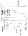
- FIG.2C shows the mixing characteristic of the mixer 13 of FIG.2A for a case in which methanol is used for the solvent A and a mixture of methanol and a small amount of acetone (0.05 volumetric percent) is used for the solvent B.
- the mixing ratio is controlled stepwise according to a program curve shown at the left of FIG.2C while simultaneously detecting the acetone content in the solvents thus mixed.
- the curve at the right of the program curve represents the actual or measured mixing ratio.
- the mixer 13 of FIG.2B is proposed for eliminating the foregoing problem of the mixer of FIG.2A.
- the chamber 13b of the mixer is filled with small beads 13c, and the solvents A and B are caused to flow through irregular paths of fluid formed between the beads.
- FIG.2D shows the result of measurement of the acetone content in the mixture of the solvents.
- FIG.2C it should be noted that the mixing of the solvents A and B is carried out according to the same program curve shown in FIG.2C.
- FIGS.3A and 3B show the construction of the sampler 14 used in the liquid chromatograph of FIG.1.
- the sampler 14 is essentially formed of a six-port valve including a rotary valve body 14R, wherein the rotary valve body 14R is formed with six passages 141 - 146, and there are formed three interconnecting passages 14a - 14c each connecting two of the foregoing six passages 141 - 146.
- the passage 14a connects the passages 141 and 146 with each other
- the passage 14b connects the passages 142 and 143 with each other
- the passage 14c connects the passages 145 and 146 with each other.
- the passage 141 is aligned to a port P that in turn is connected to the mixer 13, the passage 142 is aligned to a part A1 connected to an end of a sample accumulation loop 147 to be described later, the passage 143 is aligned to a port S connected to the syringe 15, the passage 144 is aligned to a port D connected to the waste reservoir 18, the passage 145 is aligned to a port A2 connected to the other end of the loop 147, and the passage 146 is aligned to a port C connected to the column 16.
- the solvents A and B from the mixer 13 are supplied to the column 16 via the foregoing passages 141, 14a and 146, consecutively.
- the rotary valve body 14R is rotated in the direction of arrow, and as a result, the port P now aligns to the loop 147 via the passages 142, 14b and 143. Further, the port C aligns to the passages 141, 14a and 146. As a result, the solvent supplied from the mixer 13 carries the sample solution, held in the loop 147, to the column 16 via the port C. In other words, injection of the sample solution to the column 16 is carried out. Further, the syringe 15 is connected to the waste reservoir 18 via the passages 144, 14c and 145.
- FIG.4 shows the construction of the six-port valve 14 in an exploded view.
- the six-port valve 14 includes a stationary cap 14S acting as a stationary member on which the rotary valve body 14R is mounted rotatably. Further, the six-port valve 14 includes another valve body 14R2 that carries the foregoing passages 14a - 14c.
- the rotary valve 14R carries thereon the passages 141 - 146 in the form of straight, tubular passages, while the cap 14C carries the foregoing ports P, A1, S, D, A2 and C in alignment with the passages in the rotary valve body 14R.
- the passages 14a - 14c on the valve body 14R2 are generally formed with a tolerance such that passages 141 - 146 align positively with the corresponding passages 14a - 14c, even in the case where there exists an error in the precision of machining the passages.
- a tolerance invites an increase in the size of the passages 14a - 14c as indicated in FIG.5, wherein it will be noted that a dead space 14ax is formed such that a part of the sample solution supplied to the loop 147 from the mixer 13 dwells in such a dead space.
- a dead space 14ax inevitably invites incomplete supply of the sample solution to the column 16, and there occurs an error in the detection carried out by the detector 17.
- the rotary valve body 14R of FIG.4 has been generally actuated by a stepping motor.
- the stepping motor rotates, in response to an external drive control signal, with a predetermined angle, and the switching of the fluid passage is achieved as a result.
- the cap 14S, the valve body 14R and the valve body 14R2 are all formed of metal in view of mechanical durability and durability against abrasion.
- the conventional liquid chromatograph requires an external controller such as a microcomputer for driving the stepping motor, and the construction for recovering the sample solution after the analysis can be realized only in those apparatuses having such a microcomputer as a controller.
- valve 14 is formed of metals
- the conventional valve 14 is vulnerable to corrosion caused by the sample solution or solvents, and there has been a substantial risk that the result of analysis is unreliable due to the contamination caused by the corrosion of the valve 14. Further, the operation of the valve 14 may become unreliable due to the corrosion or wear.
- FIG.6 shows a sample injection needle 22 provided in the sampler 14 for injecting the sample solution to the column 16.
- the sample solution is indicated by a matting 30.
- the injection needle 22 is used for injecting a cleaning solution 31 when the liquid chromatograph is in the cleaning mode.
- the needle 22 is provided at an end of a tube 32 extending to the syringe 15, wherein it will be noted that the connection between the needle 22 and the tube 32 is achieved by an intervening member 37.
- the cleaning solution is filled in the injection needle 22 as well as in the tube 32 prior to the injection of the sample solution 23, and a suction of the air is made to form an air gap 33 in the needle 22.
- the sample solution 30 may be adsorbed on the inner wall of the piping extending to the column 16, when an injection of the sample solution 30 is made. Thereby, there is a possibility that the sample solution 30 that reaches the column 16 and further to the detector 17 is lost by an amount corresponding to those adsorbed on the inner wall of the piping, and there is a problem that such a decrease of the sample causes an error in the result of the measurement. This problem of error becomes particularly pronounced in the chromatographs in which the amount of injected sample solution is small, in the order of 2 ⁇ l or less.
- FIG.7 shows a conventional dual-column liquid chromatographic separation system, wherein there is provided a prefocusing column (precolumn) 40 between an automatic sampler 14 and a six-port switching valve 10, wherein the syringe 15 described before and a cooperating mechanism are collectively designated by the reference numeral 14. Further, a solvent-pumping system including the pumps 11A and 11B cooperates with the six-port valve 10.
- the precolumn 40 concentrates a sample or target substance that has been injected by the sample injector into a solvent A supplied by the pump 11A, and the substance thus concentrated is transferred further to the secondary column (separation column) 16 for separation together with a solvent B supplied by the pump 12.
- the six-port valve 10 is switched between a first state and a second state, wherein, in the first state, the sample injected to the solvent A by the autosampler 14 is fed to the valve 10 after passing through the precolumn 40 and forwarded further to a waste reservoir along a path indicated by a continuous line, wherein the sample alone is captured by the precolumn 40.
- the solvent B is supplied to the valve 10 and forwarded to the separation column 16 along another continuous line shown in FIG.7.
- the concentrated sample from the precolumn 40 is now caused to flow to the separation column 16 along a path shown by a broken line in FIG.7 for analysis, while the solvent B from the pump 2 is caused to flow to the waste reservoir along a path shown by another broken line.
- the valve 10 there has been a problem of dead volume in the valve 10. Because of the existence of such a dead volume, the switching of the fluid in the six-port valve 10 has not been complete.
- the condensation column 40 is filled with a packing material that carries out the desired condensation of the sample solution.
- a packing material used in the condensation column 40 causes an adsorption of proteins, particularly when the liquid chromatograph is used for separation and analysis of mixtures that contain a large amount of proteins such as a serum.
- the adsorption of the proteins on the filler causes a substantial decrease in the effectiveness of the column filler for concentrating the sample solution.
- a process has been necessary for removing the proteins from the sample solution before it is supplied to the condensation column 40.
- Such a preparation of the sample solution is undesirable in view of extraneous time needed and possible degradation in the precision or reliability of the analysis.
- the Japanese Laid-open Patent Publication 60-56256 describes an example of such an improved filler.
- a protein covers the outer surface of a silica body on which octadecylsilil (ODS) is bonded.
- ODS octadecylsilil
- the protein used herein may be bovine serum albumin and modifies the silica surface thus treated with ODS.
- the adsorbed protein is generally released from the surface after prolonged use. Further, such a conventional filler cannot provide a column having high efficiency of separation.
- a porous silica medium infiltrated with glyceryl propyl group is used as a starting material, and oligopeptide is bonded thereto via carbonyl diimidazole. Further, the phenylalanine side chains on the outer surface of the silica medium are disconnected by means of carboxypeptidase A, which is a proteoysis enzyme.
- carboxypeptidase A which is a proteoysis enzyme.
- the inner surface of the column filler is covered by glycyl-phenylalanyl phenyl-alanine acting as a hydrophobic ligand, while the outer surface of the filler is covered with hydrophilic glycyl-glyceryl propyl group.
- a porous silica body infiltrated with aminopropyl group is used as a starting material, and hydrophobic group is introduced by amide bonding by causing a reaction of octanoylchloride under presence of triethylamine.
- acyl group on the outer surface of the silica filler is subjected to hydrolysis reaction, and amino group on the outer surface is made hydrophilic by causing a reaction with glycidol.
- the column filler disclosed in the foregoing '152 or '145 reference has a drawback in that, because of use of enzyme reaction, the construction of the column filler becomes complex and the property of the obtained column filler tends to vary variously.
- micro-column liquid chromatographs In spite of these various promising perspectives, practical use of the micro-column liquid chromatograph has not been successful so far, probably due to the instability in the flow rate control and the poor column stability. It should be noted that the stability of the isocratic is essential in the flow rate mode for managing the retention time. Further, such micro-column liquid chromatographs generally have a very basic problem of discrepancy between the volume of the prepared sample solution, typically in the order of several ten micro-litters to several hundred micro-litters, and the volume of the injected sample solution in the liquid chromatograph, which is typically in the order of several micro-litters. When the concentration level of the chemical substance to be analyzed is extremely low in the sample solution, it is naturally desired to use the entirely of the prepared sample solution for the analysis, while the conventional micro-column liquid chromatographs cannot meet such a demand.
- the flow rate of the sample solution in the column 16 has to be set low, in the order of micro liters per minute when a micro-column is used. This level of flow rate is substantially smaller than those used in a semi-micro-column in which the flow rate is typically set to be about 0.05 - 0.2 ml/min. With reducing diameter of the column 16, the flow rate of the sample solution therein decreases further. Thus, in the construction of the liquid chromatograph of FIG.7 where the condensation column 40 having a large diameter is connected directly to the micro-column 16, there inevitably occurs a problem of increased time for conducting the measurement. Thereby, the efficiency of analysis is substantially deteriorated.
- Another and more specific object of the present invention is to provide a liquid chromatograph equipped with a mixer that enables substantially complete mixing of solvents oven in a very low flow rate of the supplied solvents.
- Another object of the present invention is to provide a liquid chromatograph equipped with a sampler for supplying a sample solution to a separation column, wherein the sampler supplies the sample solution to the column substantially completely.
- Another object of the present invention is to provide a liquid chromatograph, comprising: a plurality or pumps for supplying a plurality of solvents; mixing means supplied with said plurality of solvents from said plurality of pumps for mixing said plurality of solvents; control means for controlling a mixing ratio of said solvents in said mixing means; a chromatograph column supplied with said solvents from said mixing means for separating a sample that is carried with said solvents; flow path control means provided between said mixing means and said chromatograph column for receiving said solvents from said mixing means and further with said sample, said flow path control means supplying said sample together with said solvents to said chromatograph column; and detection means supplied with said sample separated by said column, for detecting said sample supplied thereto; said mixing means comprising a mixing chamber and a porous medium accommodated in said mixing chamber, said porous medium extending between a first end for receiving said solvents from said pumps and a second end for supplying said solvents to said flow path control means and having a size and shape in conformity with a size and shape of
- the mixing of the solvents occurs in the porous medium.
- no substantial dead space is formed between the porous medium and the mixing chamber, and the solvents supplied to the mixing chamber are mixed more or less completely as they pass through the porous medium from the first end to the second end.
- an exact control of composition of the solvents is achieved when the liquid chromatograph is employed for a gradient elution in which the composition of the solvent is controlled according to a program curve.
- Another object of the present invention is to provide a liquid chromatograph, comprising: a plurality of pumps for supplying a plurality of solvents; mixing means supplied with said plurality of solvents from said plurality of pumps for mixing said plurality of solvents; control means for controlling a mixing ratio of said solvents in said mixing means; a chromatograph column supplied with said solvents from said mixing means for separating a sample that is carried with said solvents; flow path switching means for switching a path of said solvents, said valve means comprising; first flow path means provided between said mixing means and said chromatograph column for receiving said solvents from said mixing means and further with said sample, said flow path means supplying said sample together with said solvents to said chromatograph column; second flow path means supplied with said sample for supplying said sample to said chromatograph column together with said solvents; third flow path means for selectively causing said second flow path means to communicate with a waste reservoir; and a sample holder supplied with said sample for holding said sample therein; detection means supplied with said sample separated by said chromatograph column
- the second surface or bottom surface of the valve body carries the passage of fluid in the form of grooves, it is no longer necessary to provide the passage of the fluid in the seal member with tolerance, and the problem of formation of dead space due to the tolerance of the groove on the seal member is successfully eliminated.
- Another object of the present invention is to provide a liquid chromatograph, comprising: a pump for pumping a solvent; a chromatograph column supplied with said solvent from said pump for separating a sample from said solvent; first flow path control means disposed between said pump and said chromatograph column, said first flow path control means being supplied with said solvent and further with a sample for supplying said solvent and said sample, supplied to said first flow path control means, together to said chromatograph column; detection means supplied with said sample from said column after separation, for detecting said sample supplied thereto; a sample holder mechanism including a plurality of vessels containing a plurality of samples; sample injection means for selectively collecting a sample from one of said plurality of vessels for supplying said collected sample to said first flow path control means; and second flow path control means for selectively supplying said sample from said detection means, after detection in said detection means, to said sample injection means; wherein said sample injection means stores said sample supplied from said second flow path control means in one of said vessels in said sample holder mechanism.
- the second flow path control means selectively supplies the sample, after separation in the chromatograph column and analysis in the detection means, to a vessel in the sample holder mechanism, such that the samples after the chromatographic analysis are held in the sample holder mechanism together with the samples yet to be analyzed.
- the liquid chromatograph has a compact size.
- the first and second flow path control means are easily realized by a six-port valve mechanism having six ports and three fluid passages each connecting two of the six ports.
- the present invention is particularly useful in the liquid chromatograph having a semi-micro or micro column in which the total flow rate of the solvent and the sample is held at a level of 200 ⁇ l/min or less.
- Another object of the present invention is to provide a process for analyzing a sample by means of a liquid chromatograph, comprising the steps of:
- Another object of the present invention is to provide a liquid chromatograph, comprising: a chromatographic column supplied with a sample solution together with a solvent for separating said sample solution; detection means supplied with said sample solution from said chromatographic column for detecting said sample solution supplied thereto; a piping system connected to said chromatographic column for supplying said sample solution to said chromatographic column; a first vessel for holding said sample solution; a second vessel for holding an inert solution that does not affect a detection of said sample solution; sample injection means for pulling said sample solution from said first vessel and for holding said sample solution in the form of a sample liquid droplet, said sample injection means further pulling said inert solution from said second vessel and holding said inert solution in the form of an inert liquid droplet, said sample injection means injecting said sample liquid droplet and said inert liquid droplet to said piping system; and injection control means for controlling said sample injection means such that said sample injection means holds one or more of said inert liquid droplets separated from each other by one or more air gaps and such that said
- the sample liquid left on a wall of a tube extending to the chromatographic column is grabbed and transported to the column, together with one or more of the inert liquid droplets that follow the sample liquid droplet.
- Another object of the present invention is to provide a dual-column chromatograph having a condensation column for concentrating a sample solution prior to a secondary chromatographic analysis, wherein the volumetric capacity of the condensation column is set small enough for use in combination with a semi-micro or micro separation column.
- Another object of the present invention is to provide a liquid chromatograph, comprising: a pump for pumping a solvent: a separation column supplied with a sample solution for separating a sample contained therein; detection means for detecting said sample separated by said separation column; sample injection means supplied with said solvent from said pump for injecting a sample to said solvent to produce a sample solution, said sample solution containing said sample in said solvent; and a condensation column provided between said injection means and said separation column, said condensation column being supplied with said sample solution from said sample injection means for concentrating said sample to produce a concentrated sample solution, said condensation column supplying said concentrated sample solution to said separation column as said sample solution; wherein said condensation column has a volumetric capacity less than 2 milliliters; and wherein said condensation column is filled with a column filler of a porous medium covered by a silicone polymer having a Si-R bond and a Si-R' bond, wherein R represents a hydrophobic group and R' represents a hydrophilic group.
- the present invention that uses a column having a small volumetric capacity for the condensation column, one can eliminate the problem of unwanted dilution of the sample solution in the condensation column, and it is possible to obtain an accurate analysis as a result of condensation of the sample solution.
- a porous medium covered by a silicone polymer having an Si-R bond or Si-R' bond it is possible to eliminate the adsorption of protein on the outer surface of the column filler, and a reliable condensation of the sample solution can be achieved. It should be noted that the present invention does not rely upon enzyme reaction.
- Another object of the present invention is to provide a multi-column liquid chromatograph, comprising: at least two pumps for pumping respective solvents; a separation column for separating a sample transferred from a previous column; detection means for detecting said sample separated by said separation column; sample injection means supplied with said solvent from said pump for injecting a sample to said solvent to produce a sample solution, said sample solution containing said sample in said solvent; and a plurality of procolumns provided between said injection means and said separation column for concentrating a sample solution supplied thereto; wherein at least one of said precolumns has a larger diameter than that of a separation column.
- the present invention it is possible to achieve a stable and effective condensation of the sample solution before the separation of the sample is achieved in the separation column. As a result, a high sensitivity analysis is possible for a dilute sample solution.
- precolumn(s) it is possible to prevent the decrease of flow rate of the mobile phase in the first stage separation, and the problem of increased time for the analysis is effectively eliminated.
- the present invention is particularly advantageous for those liquid chromatographs that use a semi-micro or micro column for the separation column. It should be noted that the sensitivity of detection is maximized in such a semi-micro or micro column liquid chromatograph due to the decreased flow rate of the sample solution in the second stage separation.
- such a decreased flow rate in the separation column is advantageous in view point of supplying the sample solution further to other analytical apparatuses such as a mass spectrometer.
- such a reduced flow rate of the sample solution is preferable in view of reduced consumption of the solvents.
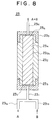
- FIG.8 shows a first embodiment of the present invention. More specifically, FIG.8 shows a mixer 23 for-use in the liquid chromatograph of FIG.1 in a cross sectional view.
- the mixer 23 is formed of a cylindrical vessel 232 of stainless steel or a plastic material wherein the vessel 232 is formed with a corresponding cylindrical mixing chamber 23 2a therein.
- the mixing chamber 23 2a has an inner diameter of 1.0 - 5.0 mm and extends for a length of 3 - 10 cm.
- the mixing chamber 23 2a is filled with a porous resin body 234 having a cylindrical shape corresponding to the cylindrical mixing chamber 23 2a , wherein it will be noted that the resin body 234 has an outer diameter of 1.0 - 5.0 mm and a length of 3 - 10 cm respectively in correspondence to the inner diameter and length of the chamber 23 2a .
- the resin body 234 has an outer diameter of 1.5 mm when the mixing chamber 23 2a has an inner diameter of 1.5 mm.
- the resin body 234 may be formed of a porous fluorocarbon resin, and is conveniently obtained by stamping a porous slab of fluorocarbon with a predetermined diameter.
- the mixing chamber 23 2a is filled with resin disks 23 4a , 23 4b , . . . thus stamped, wherein the resin disks 23 4a , 23 4b , . . . are stacked with a predetermined number to form the foregoing resin body 234 of a predetermined length.
- the mixing chamber 23 2a By filling the mixing chamber 23 2a by such resin disks, it is possible to eliminate the dead space substantially completely from the mixing chamber 23 2a .
- a pair of filters 237 and 238 of sintered stainless steel are disposed at both ends of the resin body 244, and caps 233 and 235 both of stainless steel are provided upon respective ends of the stainless steel vessel 232.
- the caps 233 and 235 carry respective ports 231 and 236 and are screwed upon the vessel 232 at the ends of the vessel 232.
- port 231 has branched ends 23 1a and 23 1b , wherein the solvent A is supplied to the end 23 1a by means of the pump 11A.
- the solvent B is supplied to the end 23 1b by means of the pump 11B.
- the solvents A and B thus supplied are mixed with each other as they flow through the porous resin body 234 and is exhausted from the outlet port 236.
- FIG.10 shows the construction of a six-port valve 24 that is used in the liquid chromatograph of FIG.1 in place of the six-port valve 14.
- the six-port valve 24 includes a stationary cap 24S substantially identical to the stationary cap 14 of FIG.4, and a rotary valve body 24R engages with the foregoing stationary cap 24S. More specifically, the rotary valve body 24R has a cylindrical shape defined by a first end surface 24f and a second, opposite end surface 24g and is mounted upon the stationary cap 24S such that the end surface 24f establishes a slidable, yet intimate engagement with the cap 24S. As a result, a seal is formed between the rotary valve body 24R and the stationary cap 24S. Further, there is provided another cap 24R2 on the end surface 24g of the rotary valve body 24R.
- the rotary valve body 24R there are provided six straight fluid passages 241 - 246 extending from the end surface 24f to the end surface 24g similarly to the rotary valve body 14R of FIG.4.
- the rotary valve body 24R of FIG.10 carries grooves 24a - 24c on the end surface 24g as the passage of the fluid.
- the groove 24a connects the passages 241 and 246, the groove 24b connects the passages 242 and 243, and the groove 24c connects she passages 244 and 245.
- no groove is provided on the cap 24R2.
- the rotary valve body 24R may be formed of a ceramic or resin.
- the grooves 24a - 24c may be formed on a green body by machining, simultaneously to the formation of the fluid passages 241 - 246.
- the valve body 24R is formed of a resin such as PEEK (polyether etherketone)
- the grooves 24a - 24c may be formed either simultaneously to the molding of the valve body 24R or by machining the end surface 24g of the valve body 24R thus formed. In any of these processes, it should be noted that the grooves 24a - 24c are formed with an exact alignment with the fluid passages 241 - 246.
- cap 24R2 may be a mere disk that is fixed firmly upon the rotary valve body 24R by a suitable means such as screws. Of course, there is formed a tight seal at the interface between the valve body 24R and the disk 24R2.
- FIG.11 shows a construction for mounting the six-port valve or FIG.10 on the liquid chromatograph of FIG.1.
- valve bodies 24R and 24R2 are accommodated together in a casing 24C of stainless steel, and the stationary cap 24S is fitted upon the casing 24C by screwing. Further, the valve bodies 24R and 24R2 are mounted upon a rod 24D so as to be rotated integrally with the rod 24D. Further, the stationary cap 24S includes various threaded holes for receiving insertion of various pipings shown in FIG.1. Further, there is provided a guide member 24i on the cap 24S for receiving the sample injection tube of the syringe 15 that holds the sample solution.
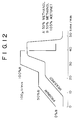
- FIG.12 shows the response for switching the solvents for a case in which the combination of the mixer 23 of FIG.8 and the six-port valve 24 of FIG.10 is used in the liquid chromatograph of FIG.1.
- the experimental conditions are set substantially the some as in the case of FIGS.2A - 2D, except that the total flow rate is set to 100 ⁇ l/min.
- the liquid chromatograph of the present invention can provide a sufficient response with respect to the switching of the solvent or sudden change in the composition of the solvent, even in the case of such a small total flow rate.
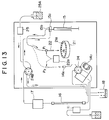
- the liquid chromatograph includes a sample holder 21 including a plurality of sample vials 21a for holding the samples to be analyzed.
- Each of the vials 21a has a volumetric capacity of about 200 ⁇ l, and there is provided a robot 22a for carrying the sample injection needle 22 movably between a position P1 and a position P2 such that the sample injection needle 22 is inserted into one of the vials 21a when in the position P1.
- the sample injection needle 22 is connected to the syringe 15 by means of a tube, and the syringe 15 picks up the sample in the vial 21a via the needle 22.
- sample loop 147 is formed with an injection port 14x adapted for receiving the noodle 22, and the sample held in the syringe 15 is injected to the loop 147 via the injection port 14x upon movement of the needle 22 to the position P2 corresponding to the injection port 14x.
- a second six-port valve 24B at the outlet of the detector 17, wherein the second six-port valve 24B supplies the sample, ejected from the detector 17 after analysis, selectively either to the waste reservoir 18 or the sample injection needle 22.
- the sample ejected from the detector 17 after analysis is supplied to the waste reservoir 18 along a feed path indicated by arrow.
- the sample injection needle 22 When feeding the ejected sample to the sample injection needle 22, on the other hand, the sample is supplied to the needle 22 via a flow path 15b provided in a T-joint 15a. It should be noted that the flow path 15b in the T-joint 15a supplies any of the sample fed from the syringe 15 and the sample from the valve 24B to the sample injection needle 22.
- the illustrated apparatus includes a vessel 25A for holding a rinsing liquid used for cleaning the column 16 as well as the piping system cooperating therewith, such that the rinsing liquid in the vessel 25A is supplied to the foregoing six-port valve 24B by means of a pump 25.
- the rinsing liquid is supplied to the needle 22 via the joint 15a for cleaning the needle 22.
- the robot 22a moves the needle 22 to a cleaning position P3 different from any of the foregoing positions P1 and P2.
- FIG.14 shows the state in which the six-port valve 24B has rotated with respect to the state of FIG.13.
- the sample ejected from the detector 17 passes through the valve 24B along a path indicated by an arrow and supplied to the sample injection needle 22 via the flow path 15b in the T-joint 15a.
- the rinsing liquid from the vessel 25A is blocked at the valve 24B.
- the total flow rate of the solvent is at boat 50 - 200 ⁇ l/min.
- the dilution of the ejected sample by the solvent does not cause any problem at all, and the sample thus collected is successfully stored in the vial 21a typically having a volumetric capacity of several hundred micro-litters, which is sufficient for accommodating the collected sample.
- FIGS.15A and 15B show the switching of flow path of the sample ejected from the detector 17 by the six-port valve 24B.
- the six-port valve 24B includes a rotatable valve body 23R that carries thereon straight passages 241B - 246B as well as passages 24aB - 24cB connecting the passages 241B - 246B.
- the passage 24aB connects the passages 241B and 246B
- the passage 24bB connects the passages 242B and 243B
- the passage 23c connects the passages 235 and 236.
- the passage 241B matches a port I that is connected to the sample injection needle 22 via the T-joint 15a
- the passage 242B matches a port D connected to the outlet of the detector 17
- the passage 243B matches a port W connected to the waste reservoir 18.
- the passage 246B matches a port C connected to the vessel 25A that holds the rinsing liquid, while the passages 245B and 24 6B are connected nowhere.
- the sample ejected from the detector 17 is supplied to the waste reservoir 18 after passing through the passage 23b and the port W.
- the cleaning solution in the vessel 25A is connected to the sample injection needle 22 via the passage 24aB.
- the valve body 24RB is rotated in the direction of the arrow, and the port I is connected to the detector 17 via the passages 242B, 24bB and 243B. Further, the port C is connected to the passages 241B, 24aB and 246B. On the other hand, the passage 246B is connected nowhere. Thus, the rinsing liquid from the vessel 25A is blocked at the passage 246B.
- the port W connected to the waste reservoir 18 is now connected to the passage 245B via the passage 23cB. However, no ejection of the sample to the waste reservoir 18 occurs in this state, because of the absence of the port connected to the passage 245B.
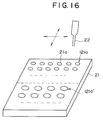
- FIG.16 shows a modification of the third embodiment.
- the sample holder 21 is formed in a rectangular shape, and the vials 21a are formed on the sample holder 21 in rows and columns. Thereby, two regions 121a and 121a' are formed on the sample holder 21 such that the vials in the region 121a have a size different from the vials in the region 121a'.
- the vials in the region 121a' have a larger volumetric capacity as compared with the vials in the region 121a. Thereby, the storage of the recovered sample is possible even in the case the sample ejected from the detector 17 has an increased volume due to dilution by solvents.
- FIG.17 showing a valve unit 50 for use in the liquid chromatograph of FIGS.13 and 14.
- FIGS.13 and 14 uses two six-port valves 14 and 23.
- the valve unit of FIG.17 of the present invention thus assembles the valves 14 and 23 in the form of a single valve unit 50.
- the valve unit 50 has a case 51 that includes a front panel 52 on which a display device 53, a key pad 54 and a power switch 55 are provided.
- FIG.18 shows the interior of the case 51.
- the case 51 includes a first valve actuation motor 62 for actuating the six-port valve 14 and a second valve actuation motor 63 for actuating the six-port valve 24B, wherein the motor 62 actuates the valve 14 via a reduction mechanism 64. Similarly, the motor 63 actuates the valve 24B via a reduction mechanism 65.
- a printed circuit board 66 in the case 51 of the valve unit 50, wherein the printed circuit board 66 carries thereon a microcomputer 68 for controlling the motors 62 and 63 and a switching regulator 67.
- the display device 53 on the front panel 52 may be a liquid crystal display and represents the status or the valve unit 50 including the content inputted via the key pad 54. It should be noted that the key pad 54 is used for various settings of the valve unit 50 as well as for inputting programs and data to the microcomputer 68.
- the power switch 55 is used for turning on and turning off the electric power of various electronic components inside the valve unit 50.
- the switching regulator 67 acts as a stabilized power supply by causing a high frequency switching of the input electric power.
- the motor 62 for driving the valve 14 may be a d.c. motor and has an output shaft connected to the valve 14 via the reduction mechanism 53 described already.
- the motor 64 may be a d.c. motor and has an output shaft connected to the valve 24B by way of the reduction mechanism 65.
- the motors 62 and 63 are driven under control of the microcomputer 68, and the switching of the flow path described previously with reference to FIGS.3A and 3B for the valve 14 or with reference to FIGS.15A and 15B for the valve 24B is achieved.
- microcomputer 68 for controlling the motors 62 and 63 are provided in the form of integral unit 50, there is no need to provide an external controller outside the unit 50. Associated with this, it is possible to eliminate various wirings and electric connections associated with the use of external controllers.
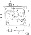
- FIGS.19 and 20 corresponding to FIGs.13 and 14 described previously.
- those parts described already with reference to FIGS.13 and 14 are designated by the same reference numerals and the description thereof will be omitted.
- the liquid chromatograph includes a system controller 70, wherein the system controller 70 controls the robot 22a and the sample holder 21 and further the syringe 15, wherein the system controller 70 controls the syringe 50 by way of an actuator 39 as well as the valve 14 and the pump 25.
- the vessel 38 is provided in the vicinity of the sample holder 21 such that the sample injection needle 22 can pick up the liquid held in the vessel 38 at a position P3, which is different from any of the positions P1 and P2.
- the system controller 70 controls the sequence of pulling of the sample into the needle 22, such that the inert liquid held in the vessel 38 is pulled first, followed by pulling in of the sample, with an intervening suction of an air gap.
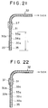
- a droplet 30a of the sample is held in the sample injection needle 22 provided at an end of the tube 32, wherein it will be noted that the tube 32 is filled by the rinsing liquid 31 and one or more droplets 30b of the inert liquid is held in the needle 22 separated from the rinsing, liquid 31 and from the sample 30a by gaps 33a as indicated in FIG.21 or FIG.22.
- the system controller 70 When injecting the sample droplet 30a to the sample loop 147, the system controller 70 energizes the actuator 39 of the syringe 15 such that the sample droplet 30a is injected first, followed by the injection of one or more of the inert liquid droplets 30b.
- the inert liquid forming the droplets 30b is formed of a substance that does not react to or modify the composition of the sample droplet 30a.
- FIG.23 shows the construction of the 22a in detail.
- the robot 22a has a base body 240 and an arm 244 held movably with respect to the body 240. It should be noted that the base body 240 in turn is held movable on horizontal shafts 241a and 241b in the X-direction. Further, it should be noted that the arm 244 is movable along vertical shafts 245a and 245b mounted upon the body 240 in the Z-direction.
- the body 240 of the robot 22a is mounted upon a chassis not illustrated, and the body 240 is moved in the X-direction with respect to the chassis by means of a stepping motor 242 and a cooperating timing belt 243.
- the base body 240 in turn carries a stepping motor 246, and the stepping motor 246 driven the arm 244 in the Z-direction by means of a timing belt 247.
- the arm 244 carries the foregoing sample injection needle 22 by means of a connector 249. Further, there is provided a protective guide 248 on the base body 240 for protecting the tip end of the sample injection needle 22.
- the controller 70 of FIGS.19 and 20 energizes the stepping motors 242 and 246, and the robot 22a moves the sample injection needle 22 in the X- as well as Z-direction under control of the controller 70, As a result of such a control, the sample injection needle 22 is selectively inserted the vial 22a or into the vessel 38 that contains the inert liquid, for collecting the sample or the inert liquid into the sample injection needle 22. Further, the needle 22 is moved to the position corresponding to the injection port 14x for injecting the sample droplet 30a as well as the inert liquid droplets 30b held therein to the injection port 14x.
- the process starts with a step S10 in which the entire piping system is cleaned by flowing a rinsing liquid therethrough.
- the controller 70 activates the robot 22a in a step S12 such that the sample injection needle 22 is held at a position in which the tip end of the sample injection needle 22 is away from any of the sample injection port 14x, the sample vial 21a and the container 38 of the inert liquid.
- the controller 70 activates the syringe actuator unit 39 to cause a pulling of the air into the needle 22.
- an air gap of about 200 nl is formed in the needle 22 as indicated by the numeral 33 in FIG.21 as a result of the suction of the air.
- a step S14 is conducted to move the needle 22 into the inert liquid held in the vial 38 to pull the inert liquid into the needle 22.
- the inert liquid droplet 30b is formed in the needle 22 with a volume typically of 200 nl.
- a step S16 is conducted to move the needle 22 away from the vial 38 to pull the air into the needle 22.
- another gap 33a is formed as shown in FIG.21 with a volume typically of 200 nl.
- the robot 22a moves, in the step S18, the needle 22 into the sample liquid held in one of the vials 21a for pulling the sample liquid into the needle 22 to form a sample droplet as shown in FIG.21 by the numeral 30a.
- a step S22 is carried out in which the needle 22 is inserted into the sample injection port 14x and the sample droplet 30a in the needle 22 is injected to the sample loop 147, followed by the injection of the inert liquid droplet 30b.
- the activation of the actuator 39 is controlled such that only a part of the content of the sample injection needle 22 corresponding to the part represented by L1 is injected to the sample loop 147.
- the sample liquid droplet 30a thus injected is then fed to the column 16 further to the detector 17 via the six-port valve 14 as already explained.
- the sample droplet 30a is supplied first, followed by the inert liquid droplet 30b.
- any sample liquid that is left on the piping system is collected by the inert liquid droplet 30b and is supplied together with the sample droplet 30a to the column 16 and the detector 17.
- the loss of the sample liquid on the inner wall of the piping system is effectively eliminated by employing the feeding sequence shown in the flowchart of FIG.24, and a high precision analysis of the sample becomes possible.
- RSD relative standard deviation
- the composition of the inert liquid depends upon the composition of the sample and the composition of the cleaning solution, wherein the composition of the rinsing liquid is determined based upon the estimated composition of the sample, and the composition of the inert liquid determined based upon the composition of the rinsing liquid. It is also possible to use a rinsing liquid as the inert liquid.
- TABLE I shows various possible combinations of the cleaning solution and the inert liquid.
- the liquid chromatograph has a construction substantially identical with the system of FIG.7 except that the system uses the six-port valve 24 described in FIG.10, in place of the six-port valve 10, as a six-port valve 10A.
- the dual-valve of FIG. 17 in combination with the sample collection system described with reference to the embodiment of FIG.13.
- the precolumn 40 uses a column packing material of a porous medium covered by a silicone polymer that has an Si-R bond and an Si-R' bond, wherein R represents a hydrophobic group while R' represents a hydrophilic group.
- a column packing material By using such a column packing material, it is possible to separate proteins with high efficiency when a sample containing protein such as serum is analyzed. Thereby, an effective concentration of the target substance is achieved.
- porous media commonly used in liquid chromatography such as silica gel, alumina, porous glass beads, zeolite, hydroxyapatite and graphite may be used as the packing material of the column 40.
- composite powders formed of a resin core covered by inorganic powders such as silica gel, titanium dioxide, hydroxyapatite, and the like.
- materials such as polyamides, acrylic resins, polyvinyl alcohols, and the like, for the resin core.
- the porous medium has a diameter of 2 - 200 ⁇ m and has a specific surface area or 200 - 300 m2/g. Further, the porous medium generally has fine pores of 40 - 120 ⁇ diameter. It is particularly preferable to use a medium having a size of 3 - 50 ⁇ m in diameter and a specific surface area of 400 - 600 m2/g. The porous medium has fine pores of 60 - 80 ⁇ diameter and may have a spherical shape or irregular shape.
- the porous medium is covered with a silicone compound having a Si-H group, wherein the silicone compound is generally represented by the formula (R1HSiO) a (R2R3SiO) b (R4R5R6SiO 1/2 ) c , (1) wherein each of R1 - R3 is a hydrocarbon group having 1 - 10 carbon atoms, at least one of the carbon atoms may be substituted by a hydrogen or halogen atom. It should be noted that the case in which all or the groups R1 - R3 are formed of hydrogen is excluded.
- each of R4 - R6 represents a hydrocarbon group containing 1 - 10 carbon atoms, with at least of the carbon atoms being substituted by a hydrogen or halogen atom.
- n or a + b is preferably in the range between 3 and 7.
- the boiling point of the compound decreases.
- trimers and tetramers are preferred due to the easiness of polymerization associated with their stereochemical properties.
- cyclic silicone compound includes dihydrogen-hexamethylcyclotetrasiloxane, trihydrogen-pentamethylcyclotetrasiloxane, tetrahydrogen-tetramethylcyclotetrasiloxane, dihydrogen-octamethylcyclopentasiloxane, trihydrogen-heptamethylcyclopentasiloxane, tetrahydrogen-hexamethylcyclopentansiloxane, and pentahydrogen-pentamethylcyclopentasiloxane.
- a typical silicone compound of this group is represented as where n represents an integer between 2 - 100.
- the foregoing compound of formula (5) includes 1,1,1,2,3,4,4,4-octamethylsiloxane, 1,1,1,2,3,4,5,5,5-nonamethylpentasiloxane, and 1,1,1,2,3,4,5,6,6,6-decamethylhexasiloxane.
- the silicone compound having the general formula (1) is contacted to the forgoing porous medium either in the vapor phase state or liquid phase state.
- a hermetically sealed vessel is used, in which molecules of the foregoing silicone compound vapor are contacted with the surface of the porous medium at a temperature of less than 120 °C, preferably less than 100 °C, under a pressure of less than 200 mmHg, preferably less than 100 mmHg.
- a mixed gas of the foregoing silicone compound and a carrier gas may be used for contacting with the porous medium of the filler.
- This vapor phase process is preferably conducted for those silicone compounds such as tetrahydrotetraethylcyclotetrasiloxane, tetrahydrotetramethylcyclotetrasiloxane, and the like.
- a volatile solvent that dissolves the foregoing silicone compound such as benzene, chloroform or particularly hexane is used, and a solution of the silicone compound of 0.01 - 1 weight percent is prepared.
- the solution thus prepared is added to the porous medium with such a proportion that 0.01 - 1 parts by weight of the silicone compound is added to 1 part by weight of the medium while stirring the solution thus obtained. Thereafter, the mixture of the silicone compound and the porous medium is held at a temperature of 50 - 200 °C for more than two hours to cause a polymerization on the surface of the medium.
- the active point means a part that promotes the polymerization of the silicone compounds that includes a siloxane (Si-O-Si) bond or a hydrosylile (Si-H) bond, and includes various acid points, basic points, oxidizing points and reduction points.
- the surface polymerization proceeds until the active points on the medium are all covered by a film of silicone polymer.
- an alkaline catalyst such as sodium hydroxide, lithium hydroxide, ammonium hydroxide, and the like
- an alkyl metal catalyst such as dibuthyltin.
- the silicone polymer that covers the surface of the filler medium.
- the one being a silicone polymer in which polymerization occurs as a result of disconnection and recombination of the siloxane bond (-Si-O-Si-), and the polymer includes only the -Si-O-Si- chain.
- the other being a silicone polymer in which the polymerization occurs as a result of bridging of hydrosylile (Si-H) bonds under presence of H2O or O2.
- Si-H hydrosylile
- the foregoing two types of polymerization may occur independently or proceed simultaneously, depending upon the medium or the polymerization condition such as the temperature and catalyst. Further, the degree of polymerization may change variously.
- the silicone compound having a small molecular weight penetrates inside the minute pores on the filler medium, such that substantially entire surface of the filler medium, including the pore inner surface, is covered by the silicone compound that forms a film having a thickness of 3 - 30 ⁇ .
- the porous structure of the medium is preserved. Further, the porous structure of the medium is preserved after the deposition of vinyl compound that follows the deposition of the silicone polymer compound.
- the silicone polymer compound thus formed on the surface of the porous medium generally have a molecular weight (weight average molecular weight) of 150,000 or more. It is known that silicone compounds becomes less soluble to water or organic solvents with the progressing degree of polymerization. Thus, it is generally not possible to extract the polymer for measurement of the molecular weight. It is also not possible to measure the molecular weight of the polymer in the state that the polymer forms a coat on the surface of the medium.
- the polymers are extracted in various stages of the polymerization reaction by using chloroform. In this procedure, it was confirmed that there exists a polymer of which molecular weight reaches 150,000 in the maximum. This in turn indicates that the polymer should have a molecular weight exceeding 150,000 before it is extracted by chloroform. On the other hand, further analysis of the molecular weight is difficult.
- the silicone polymer covering the surface of the filler medium includes unreacted Si-H groups.
- hydrocarbon that contains vinyl in the molecule upon the Si-H group, it is possible to form a silicone polymer that contains the Si-C bond.
- a vinyl compound having a general formula of R8-CH CH-R9 (8) in which each of R8 and R9 may be an alkyl group containing 1 - 40 carbon or hydrogen atoms, a cycloalkenyl group containing 4 - 8 carbon atoms, and an alkenyl group that may be substituted by alkyl containing 1 - 20 carbon atoms.
- the foregoing vinyl compound includes ethylene in which both of R8 and R9 are hydrogen, a vinyl compound such as ⁇ -olefin compound in which one of the R8 and R9 is hydrogen and the other is a group other than hydrogen, a symmetric vinyl compound in which both of R8 and R9 are a group other than hydrogen, and an asymmetric vinyl compound in which R8 and R9 are different groups other than hydrogen.
- the vinyl compound includes a compound in which each of R8 and R9 is an alkyl group containing 4 - 20 carbon atoms such as a 1-hexyl group, 1-octyl group, 1-decyl group, 1-dodecyl group, 1-hexadecyl group, 1-octadecyl group, cyclohexyl group or a cyclohexenyl group; phenyl or naphtyl group; or phenyl or naphtyl group substituted by a lower alkyl group containing 1 - 4 carbon atoms.
- each of R8 and R9 is an alkyl group containing 4 - 20 carbon atoms such as a 1-hexyl group, 1-octyl group, 1-decyl group, 1-dodecyl group, 1-hexadecyl group, 1-octadecyl group, cyclohexyl group or a cyclohexenyl
- the packing material of the liquid chromatography of the present embodiment it is further necessary to modify a part of the Si-H groups of the silicone polymer coating covering the surface of the packing material, to be hydrophilic.
- tetraol according to the reaction below.
- the synthesis of tetraol is achieved as follows.
- polyol is formed by replacing diglycerin by polyglycerin, and polyol thus formed can also be used as the hydrophilic group of the present invention.
- the packing material thus obtained has a distinct advantage over conventional packing material of chemical bonding type in that the packing material is effective in a wide range of pH of 2 - 10. Particularly, it should be noted that the packing material can be used in alkali solvents and that the packing material provides an improved safety. It should be noted that conventional fillers could not be used in alkali solvents.
- the present invention eliminates the necessity of complicated sample preparation and is particularly advantageous in the liquid chromatographic analysis of various drugs or metabolic products in a biological body such as serum. It is possible to directly inject biological samples for analysis and obtain a high precision analysis. It should be noted that the packing material of the present invention is of complete polymer coated type and does not use Lewis acid. Thus, it is possible to extract basic materials such as 2-ethylpyridine or N,N'-dimethylaniline.
- the packing material of the present embodiment is formed by modifying the surface of a silicone polymer covering a porous medium to be hydrophobic, followed by a process for modifying the surface to be hydrophilic.
- a silicone polymer is used first to form a coating 112 on the surface or a porous medium 110 as indicated in FIG.27A.
- the remaining -SiH groups and a hydrophobic groups (R) 114 which contain a double bond therein, are reacted as indicated in FIG.27B to form a -SiR group.
- the amount of the hydrophobic group R and/or the reaction condition are controlled such that not the entire -SiH groups are consumed.
- the remaining -SiH groups on the silicon polymer coating 112 are reacted with a hydrophilic groups (R') 116 that contain a double bond therein, to form hydrophilic groups SiR'.
- R' hydrophilic groups
- the surface of the silicone polymer 12 shows a mixed function structure of the hydrophobic groups and simultaneously the hydrophilic groups.
- the hydrophobic-hydrophillic modification process is advantageous in view point of easy control of the introduction of the hydrophobic groups. It should be noted that the hydrophilic modification provides a particularly significant influence upon the holding characteristics of the packing material.
- the surface of a porous medium 110 is covered by a silicone polymer film 112 first as indicated in FIG.28A, followed by a process for modifying the surface to become hydrophilic as indicated in FIG.28B.
- a process for modifying the surface to become hydrophilic indicated in FIG.28B.
- the -SiH groups remaining on the surface of the silicone polymer 12 are reacted with the hydrophilic groups (R') 116 that includes therein a double bond to form -SiR' groups.
- R' hydrophilic groups
- the amount of the hydrophilic groups R' or the conduction of the reaction is adjusted such that not all of the -SiH groups on the polymer film 112 are consumed.
- the surface thus treated is further subjected to a process of FIG.28C, in which hydrophobic groups (R) 114 that includes therein a double bond, are introduced to react with the remaining -SiH groups on the surface of the silicone polymer film 112.
- the modification of the polymer surface to be hydrophilic is conducted first, it is possible to modify a large part of the surface to be hydrophilic. As a result, the adsorption of protein molecules upon the polymer surface is minimized.
- the process of modifying the surface to be hydrophilic is preferably conducted in water. It should be noted that silica gels covered by silicone polymer generally show a repellency, and the reaction starts from the surface outside the pores. Thus, it is thought that the exterior of the pores are more hydrophilic as compared with the interior of the pores. This in turn indicates that the process of becoming hydrophobic occurs more in the interior of the pore as compared with the exterior of the pores.
- the porous packing material covered with silicon polymer of the present embodiment may be formed by conducting the process of modifying the medium surface to be hydrophobic and the process of modifying the medium surface to be hydrophilic simultaneously.
- the porous medium 110 is covered by a silicon polymer to form the polymer film 112.
- the -SiH group on the surface of the silicone polymer film 112 are reacted with hydrophobic groups (R) 114 and simultaneously with hydrophilic groups (R') 116 each having a double bond at an end thereof.
- the process of the present embodiment is advantageous in that the reaction is made only once.
- the proportion of the compounds acting as a source of the hydrophobic groups such as styrene with respect to the compounds that act as a source of the hydrophilic groups such as tetraol, polyol, and the like it is possible to obtain the desired packing material due to the difference in the reactivity. It is thought that the hydrophobic compounds have smaller volume than hydrophilic compounds and have a higher reactivity.
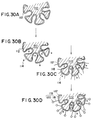
- the packing material is prepared by covering the surface of a porous packing material 110 by a silicone polymer film 112 as shown in FIG.30A, followed by a process of modifying the surface of the polymer film 112 to become hydrophobic as indicated in FIG.30B.
- hydrophobic groups (R) 114 that includes a double bond therein are reacted with the -SiH groups on the film 112.
- the reaction for introducing the hydrophobic groups is controlled, by way of control of the amount of the hydrophobic groups or the reaction condition, such that not all of the hydrophobic groups on the surface of the polymer film 112 are used.
- a process is conducted in a step of FIG.30C to introduce an epoxy compound that contains epoxy group 18 therein.
- the epoxy group 18 thus introduced have a double bond therein and are bonded with the unreacted -SiH groups on the silicon polymer film 112 by way of the double bond.
- hydrophilic groups 120 are introduced as indicated in FIG.30D, where in the hydrophilic groups 120 bond against the free end of the epoxy groups 118 previously introduced in the step of FIG.30C.
- hydrophilic groups (SiR') 116 from the epoxy groups 118 and also from the hydrophilic groups 120.
- a hydrophobic group such as a phenyl group is introduced first, followed by a bonding of acrylglycidyl ether that has a double bond at an end and an epoxy group at the other end.
- a group such as diglycerin or glycerin that has a hydrophilic group, -OH or -COOH being an example, is bonded upon the epoxy group.
- the reaction (hydrosilylation) between the hydrophobic group or the group having a double bond at an end such as acrylglycilether, is achieved under existence of Pt catalyst. Further, the reaction between the epoxy group and compounds such as diglycerine is conducted under presence of Lewis acid, quaternary ammonium salt, tertiary amine, and the like. Alternatively, it is possible to merely open the epoxy ring in a acid solution after addition of acrylglycidyl ether to form diol.
- FIGs.31A - 31C show the result of liquid chromatography obtained by the instrumentation of FIG.26, which is a modification of the construction of FIG.26 and designed for analyzing dilute samples.
- the sample solution containing the target substance is supplied, in a first state of the six-port valve 10A, from the autosampler 14 and is caused to flow through the precolumn 40 as indicated by a continuous line in FIG.26.
- the target substance is captured by the packing material of the precolumn 40 and held therein with an increased concentration level.
- the solvent B is supplied to the separation column 16 from the pump 11B without the target substance being incorporated therein.
- the valve 10A is switched to a second state wherein the solvent B is pumped into the precolumn 40 through the valve 10A.
- the target substance held in the precolumn 40 is eluted, together with the solvent B, to the separation column 16 along a path indicated by a broken line.
- FIG.31A shows a case in which a conventional column packing material is used for the precolumn 40.
- FIGS.31B and 31C show the result in which the packing material of the present embodiment is used.
- a sample diluted to a concentration level of 1/20 was introduced with an amount of 20 ⁇ l, and the concentration was made in the precolumn 40 with a duration of 3 minutes.
- a sample diluted to a concentration level of 1/80 was introduced with an amount of 80 ⁇ l, wherein the process of concentration was carried out for 3 minutes.
- the peak S of the target substance to be analyzed appears with the same sharpness as compared with the conventional case of FIG.31A, while the peak P indicative of the components not to be retained such as proteins, are suppressed substantially.
- this intensity of the sample peak S and the decreased intensity of the protein peak P indicate that the proteins are not adsorbed on the hydrophilic outer surface of the packing material in the precolumn 40.
- the column packing material of the present invention does not use enzymes, it is possible to achieve a improved stability, which in turn lead to an improved reproducibility of analysis.
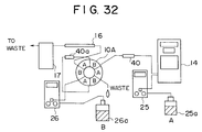
- FIG.32 those parts constructed identically with the parts described already are designated by the same reference numerals, and the description thereof will be omitted.
- a second concentration column 149 between the injection port 14x and the six-port valve 14, for concentrating the sample in a sample solution.
- the sample solution is a mixture of the sample and a first solvent to be described.
- the column 149 typically has an inner diameter of 1- 4 mm and has a relatively small length of about 10 - 50 mm.
- the column 149 thereby has a volumetric capacity of about 200 ⁇ l, and filled with a packing material that achieves the separation of the sample.
- the use of the column 149 having a small length is, although not capable of providing a necessary logical number of plates for achieving quantitative analysis, advantageous in view point of relaxing the pressure increase, particularly in the case where biological samples that tend to contain impurities are repeatedly injected.
- the velocity of the solvent or mobile phase is set to be 0.1 - 1.0 l/min.
- the sample solution that has passed through the column 40 is then supplied to the next column 40a described previously for a second concentration process, wherein the column 40a may have an inner diameter of 2.0 mm and a length of 35 mm.
- the column 40 is located in the upstream side of the column 40a.
- the embodiment of FIG.32 is constructed such that the upstream side column 40 has a larger inner diameter as compared with the downstream side column 148.
- the sample injected by the autosampler 14 travels consecutively through the columns 40 and 40a, and each time experiences a concentration.
- the sample is supplied to the separation column 16 for extraction, wherein the column 16 may typically be a micro-column and has an inner diameter of 1.0 mm and a length of 250 mm.
- the construction of using a plurality of concentration columns, at least one of which has a larger diameter than that of the main separation column, is particularly advantageous for micro-liquid chromatography that uses a micro-column or semi-micro column for the column 16.
- the valve 10A is set to a state shown in FIG.33A and the sample is injected by the autosampler 14 into the precolumn 40. Thereby, the pump 25 is driven such that a flow rate of 0.5 - 1.0 ml/min is obtained for the solvent A, and proteins or other unwanted components are caused to pass through the precolumn 40 without being captured therein.
- the solvent B is supplied to the column 40a and further to the column 16, but without the target substance to be analyzed.
- the six-port valve 10A is switched to a state of FIG.33B, wherein the sample concentrated in the precolumn 40 is now eluted and forwarded to the column 40a by the solvent A. Again, unwanted components puss through the column 40a and a concentration of the target substance occurs in the column 40a.
- the solvent B flows through the separation column 16 without being concentrated therein.
- valve 10A is switched again to the state of FIG.33A, wherein the substance concentrated in the column 40a starts migrating through the column 16.
- the flow rate is set to a level corresponding to the micro- or semi-micro-columns.
- a typical example of such a flow rate is listed in the following TABLE II as a function of the column diameter of the separation column 16.
- the concentration column 40a When the concentration column 40a has an inner diameter of 2.0 mm and the length of 35 mm, the supply of 0.5 ml sample solution, with the designed solvent flow rate of 0.25 ml/min, results in a completion of sample concentration in about 2 minutes. As the dead volume of the column 40a is in the order of 0.06 ml, the supply of the sample solution further to the column 16 is completed in about 1 minute when a column having an inner diameter of 1 mm is used for the column 16.
- the volume of the sample solution flowing into the column 16 becomes minimum in correspondence to the dead volume of the column 40. Thereby, the operation of the separation column 16 for separating the sample is stabilized substantially.
- the liquid chromatograph of the present embodiment eliminates the direct communication between the column 40 and the column 16.
- the column 40 by no means experience, a high pressure exceeding 10 MPa in any moment of the liquid chromatographic analysis.
- increased pressure in the concentration column invites a decreased precision of the analysis. In the present embodiment, such a degradation of the analysis does not occur.
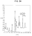
- FIG.34 shows the result of analysis of carbamabipine used for an antipileptic.
- the detection is made by the detector 17 that detects an ultraviolet absorption having a wavelength of 254 nm.
- the separation was made at 40 °C for the amount of injected sample of 100 ⁇ l.
- FIG.34 shove the result of the analysis obtained by the detector 17.
- the peak of the target compound of appears with an excellent S/N ratio in correspondence to the time of 21.32 minutes from the start of the detection.
- the present invention is by no means limited to the construction that uses only three columns, but is applicable also in the case where four or more columns are used.
Landscapes
- Physics & Mathematics (AREA)
- Health & Medical Sciences (AREA)
- Life Sciences & Earth Sciences (AREA)
- Chemical & Material Sciences (AREA)
- Analytical Chemistry (AREA)
- Biochemistry (AREA)
- General Health & Medical Sciences (AREA)
- General Physics & Mathematics (AREA)
- Immunology (AREA)
- Pathology (AREA)
- Sampling And Sample Adjustment (AREA)
- Treatment Of Liquids With Adsorbents In General (AREA)
Applications Claiming Priority (8)
| Application Number | Priority Date | Filing Date | Title |
|---|---|---|---|
| JP9527094A JPH07301625A (ja) | 1994-05-09 | 1994-05-09 | 液体クロマトグラフィ装置用切り替えバルブ装置 |
| JP95270/94 | 1994-05-09 | ||
| JP6099515A JPH07311187A (ja) | 1994-05-13 | 1994-05-13 | 液体クロマトグラフィ装置における試料注入方法及び注入装置 |
| JP99515/94 | 1994-05-13 | ||
| JP122702/94 | 1994-06-03 | ||
| JP12270294 | 1994-06-03 | ||
| JP23657694 | 1994-09-30 | ||
| JP236576/94 | 1994-09-30 |
Publications (1)
| Publication Number | Publication Date |
|---|---|
| EP0686848A1 true EP0686848A1 (fr) | 1995-12-13 |
Family
ID=27468311
Family Applications (1)
| Application Number | Title | Priority Date | Filing Date |
|---|---|---|---|
| EP94308278A Withdrawn EP0686848A1 (fr) | 1994-05-09 | 1994-11-10 | Chromatograph en phase liquide ayant une colonne micro ou semi-micro |
Country Status (3)
| Country | Link |
|---|---|
| US (2) | US5738783A (fr) |
| EP (1) | EP0686848A1 (fr) |
| KR (1) | KR100359189B1 (fr) |
Cited By (4)
| Publication number | Priority date | Publication date | Assignee | Title |
|---|---|---|---|---|
| US7074327B2 (en) | 2003-05-08 | 2006-07-11 | Nanostream, Inc. | Sample preparation for parallel chromatography |
| FR2908187A1 (fr) * | 2006-11-08 | 2008-05-09 | Topnir Systems Soc Par Actions | Procede pour injecter, de maniere automatisee, un echantillon dans une cellule d'un appareil d'analyse et dispositif pour sa mise en oeuvre |
| EP2068895A1 (fr) * | 2006-09-12 | 2009-06-17 | Prophy Med AB | Modulation sélective d'une chimiokine |
| DE102009032394A1 (de) * | 2009-07-08 | 2011-01-27 | Dionex Softron Gmbh | Longitudinale Mischvorrichtung, insbesondere für die Hochleistungsflüssigkeitschromatographie |
Families Citing this family (41)
| Publication number | Priority date | Publication date | Assignee | Title |
|---|---|---|---|---|
| TW520440B (en) * | 1997-03-28 | 2003-02-11 | Shiseido Co Ltd | A liquid chromatography apparatus and a packing material for the chromatographic column |
| EP0943619B1 (fr) * | 1998-03-19 | 2004-11-10 | Hitachi, Ltd. | Chip pour la séparation d'acides nucleiques, élément structurel et procédé pour sa formation |
| US6416663B1 (en) | 1998-04-03 | 2002-07-09 | Symyx Technologies, Inc. | Chromatographic column for rapid characterizations of polymers |
| US6265226B1 (en) | 1998-04-03 | 2001-07-24 | Symyx Technologies, Inc. | Automated sampling methods for rapid characterization of polymers |
| US6260407B1 (en) | 1998-04-03 | 2001-07-17 | Symyx Technologies, Inc. | High-temperature characterization of polymers |
| US6866786B2 (en) * | 1998-04-03 | 2005-03-15 | Symyx Technologies, Inc. | Rapid characterization of polymers |
| US6485648B1 (en) | 1998-05-18 | 2002-11-26 | Transgenomic, Inc. | MIPC column cleaning system and process |
| DE19926163B4 (de) * | 1998-06-19 | 2008-07-03 | Shimadzu Corp. | Flüssigchromatograph |
| JP4067685B2 (ja) * | 1999-03-26 | 2008-03-26 | 山善株式会社 | インジェクション装置 |
| US6855258B2 (en) * | 1999-04-02 | 2005-02-15 | Symyx Technologies, Inc. | Methods for characterization of polymers using multi-dimensional liquid chromatography with parallel second-dimension sampling |
| JP2000298122A (ja) * | 1999-04-14 | 2000-10-24 | Shimadzu Corp | 液体クロマトグラフ |
| US6460420B1 (en) * | 2000-04-13 | 2002-10-08 | Sandia National Laboratories | Flowmeter for pressure-driven chromatography systems |
| WO2002025268A1 (fr) * | 2000-09-25 | 2002-03-28 | Gl Sciences Incorporated | Procede et dispositif servant a recueillir et a concentrer un echantillon |
| US6613224B1 (en) * | 2000-10-06 | 2003-09-02 | Waters Investments Limited | Liquid separation column smart cartridge |
| US7066011B2 (en) * | 2001-06-07 | 2006-06-27 | Nano Solution, Inc. | Liquid chromatograph and analysis system |
| WO2003021251A1 (fr) * | 2001-08-28 | 2003-03-13 | Symyx Technologies, Inc. | Procede de caracterisation de polymeres a moyen d'une chromatographie liquide multidimensionnelle |
| JP2003075419A (ja) * | 2001-09-03 | 2003-03-12 | Shiseido Co Ltd | 液体クロマトグラフィー装置及び試料注入装置及び洗浄装置及び洗浄方法 |
| US7794994B2 (en) * | 2001-11-09 | 2010-09-14 | Kemeta, Llc | Enzyme-based system and sensor for measuring acetone |
| MXPA04004441A (es) * | 2001-11-09 | 2004-09-10 | Dow Global Technologies Inc | Un sistema a base de enzimas y sensor para medir la acetona. |
| US20040014227A1 (en) * | 2002-01-04 | 2004-01-22 | Frederick Erik D. | Apparatus, method and computer program product for automated high-throughput sampling and data acquisition |
| AU2003224953A1 (en) * | 2002-04-11 | 2003-10-27 | Bristol-Myers Squibb Company | Mass spectrometer autosampler |
| US6962658B2 (en) * | 2003-05-20 | 2005-11-08 | Eksigent Technologies, Llc | Variable flow rate injector |
| GB0320337D0 (en) * | 2003-08-29 | 2003-10-01 | Syrris Ltd | A microfluidic system |
| DE112005001172T5 (de) * | 2004-05-21 | 2008-07-17 | Waters Investments Ltd., New Castle | Flusskreislaufsteuerung einer HPLC-Pumpe mit konstantem Fluss, um einen Niedrigflussbetrieb zu ermöglichen |
| JP2008506948A (ja) * | 2004-07-13 | 2008-03-06 | ウオーターズ・インベストメンツ・リミテツド | 流体混合器アセンブリ |
| US7507337B2 (en) * | 2004-09-03 | 2009-03-24 | Symyx Technologies, Inc. | System and method for rapid chromatography with fluid temperature and mobile phase composition control |
| GB2421202B (en) * | 2004-12-15 | 2009-12-09 | Syrris Ltd | Modular microfluidic system |
| DE102005026585A1 (de) * | 2005-05-03 | 2006-11-09 | Forschungszentrum Jülich GmbH | Verfahren zur Probenaufgabe in Module sowie Adapter |
| US7555937B2 (en) * | 2006-01-20 | 2009-07-07 | Shiseido Company, Ltd. | Sample injection device, sample injection method, and liquid chromatograph |
| US20090158820A1 (en) * | 2007-12-20 | 2009-06-25 | Schlumberger Technology Corporation | Method and system for downhole analysis |
| US20110223588A1 (en) * | 2010-03-09 | 2011-09-15 | Biosample Llc | Solid Phase Nucleic Acid Extraction From Small Sample Volumes, and Release of Controlled Quantities |
| JP2012117945A (ja) * | 2010-12-02 | 2012-06-21 | Hitachi High-Technologies Corp | 液体クロマトグラフ,液体クロマトグラフ用試料導入装置、および液体クロマトグラフ用試料導入装置の洗浄方法 |
| US9239319B2 (en) | 2011-03-23 | 2016-01-19 | Regents Of The University Of Minnesota | Valve and splitting system for multi-dimensional liquid analysis |
| WO2014085003A2 (fr) | 2012-11-30 | 2014-06-05 | Agilent Technologies, Inc. | Injection d'échantillon de dérivation de mélangeur pour chromatographie en phase liquide |
| JP6035603B2 (ja) * | 2012-12-19 | 2016-11-30 | 株式会社日立ハイテクノロジーズ | 試料導入装置 |
| US11185830B2 (en) | 2017-09-06 | 2021-11-30 | Waters Technologies Corporation | Fluid mixer |
| JP2019074371A (ja) * | 2017-10-13 | 2019-05-16 | 株式会社島津製作所 | 質量分析装置を用いた特定物質監視システム |
| CN114207433A (zh) | 2019-08-12 | 2022-03-18 | 沃特世科技公司 | 用于色谱系统的混合器 |
| WO2022010666A1 (fr) | 2020-07-07 | 2022-01-13 | Waters Technologies Corporation | Agencement de mélangeur combiné pour la réduction de bruit en chromatographie en phase fluide |
| WO2022010665A1 (fr) | 2020-07-07 | 2022-01-13 | Waters Technologies Corporation | Mélangeur pour chromatographie en phase liquide |
| CN116194767A (zh) | 2020-09-22 | 2023-05-30 | 沃特世科技公司 | 连续流混合器 |
Citations (8)
| Publication number | Priority date | Publication date | Assignee | Title |
|---|---|---|---|---|
| GB2084887A (en) * | 1980-10-07 | 1982-04-21 | Bruker Analytische Messtechnik | Mixing chamber |
| EP0092860A1 (fr) * | 1982-04-28 | 1983-11-02 | Duphar International Research B.V | Précolonne pour préconcentrer des substances à séparer par chromatographie, ainsi que dispositif pour un système de chromatographie liquide et un organe de couplage pour ce dispositif |
| JPS60183554A (ja) * | 1984-03-01 | 1985-09-19 | Hitachi Ltd | 微少流量液体クロマトグラフ |
| US4577492A (en) * | 1983-05-12 | 1986-03-25 | Phillips Petroleum Company | Analytical method and apparatus |
| EP0495255A1 (fr) * | 1991-01-17 | 1992-07-22 | Lc Packings Nederland B.V. | Processeur de microdébit |
| US5135649A (en) * | 1989-10-02 | 1992-08-04 | Shiseido Company Ltd. | Column packing material with both hydrophobic and hydrophilic groups and process for production thereof |
| JPH0572190A (ja) * | 1991-02-28 | 1993-03-23 | Shiseido Co Ltd | カラム充填剤及びその製造方法 |
| US5277813A (en) * | 1988-06-17 | 1994-01-11 | S.A.C. Corporation | Shielded stationary phases |
Family Cites Families (6)
| Publication number | Priority date | Publication date | Assignee | Title |
|---|---|---|---|---|
| JPS6056256A (ja) * | 1983-09-08 | 1985-04-01 | Toyo Soda Mfg Co Ltd | 試料の除たん白質法および除たん白質用カラム |
| US4544485A (en) * | 1984-08-31 | 1985-10-01 | Purdue Research Foundation | Chromatographic method and means |
| US4743377A (en) * | 1985-07-02 | 1988-05-10 | Shiseido Company Ltd. | Packing material for liquid chromatography |
| JPH01123145A (ja) * | 1987-11-07 | 1989-05-16 | Japan Spectroscopic Co | カラム用充填剤及びその製造方法 |
| US5173163A (en) * | 1990-01-11 | 1992-12-22 | Isco, Inc. | Capillary electrophoresis technique |
| JP2558007B2 (ja) * | 1990-10-31 | 1996-11-27 | 株式会社資生堂 | 液体クロマトグラフィー用充填剤およびその製造方法 |
-
1994
- 1994-11-10 EP EP94308278A patent/EP0686848A1/fr not_active Withdrawn
- 1994-11-11 KR KR1019940029561A patent/KR100359189B1/ko not_active IP Right Cessation
-
1996
- 1996-12-12 US US08/766,602 patent/US5738783A/en not_active Expired - Fee Related
-
1998
- 1998-01-09 US US09/005,161 patent/US6063283A/en not_active Expired - Fee Related
Patent Citations (8)
| Publication number | Priority date | Publication date | Assignee | Title |
|---|---|---|---|---|
| GB2084887A (en) * | 1980-10-07 | 1982-04-21 | Bruker Analytische Messtechnik | Mixing chamber |
| EP0092860A1 (fr) * | 1982-04-28 | 1983-11-02 | Duphar International Research B.V | Précolonne pour préconcentrer des substances à séparer par chromatographie, ainsi que dispositif pour un système de chromatographie liquide et un organe de couplage pour ce dispositif |
| US4577492A (en) * | 1983-05-12 | 1986-03-25 | Phillips Petroleum Company | Analytical method and apparatus |
| JPS60183554A (ja) * | 1984-03-01 | 1985-09-19 | Hitachi Ltd | 微少流量液体クロマトグラフ |
| US5277813A (en) * | 1988-06-17 | 1994-01-11 | S.A.C. Corporation | Shielded stationary phases |
| US5135649A (en) * | 1989-10-02 | 1992-08-04 | Shiseido Company Ltd. | Column packing material with both hydrophobic and hydrophilic groups and process for production thereof |
| EP0495255A1 (fr) * | 1991-01-17 | 1992-07-22 | Lc Packings Nederland B.V. | Processeur de microdébit |
| JPH0572190A (ja) * | 1991-02-28 | 1993-03-23 | Shiseido Co Ltd | カラム充填剤及びその製造方法 |
Non-Patent Citations (4)
| Title |
|---|
| H.M. RUIJTEN ET AL.: "the use of conical precolumns in chromatographic analysis", TRAC, TRENDS IN ANALYTICAL CHEMISTRY., vol. 6, no. 5, June 1987 (1987-06-01), CAMBRIDGE GB, pages 134 - 138, XP026592273, DOI: doi:10.1016/0165-9936(87)87056-5 * |
| L.-E. EDHOLM ET AL.: "automated bioanalysis of drugs using coupled column liquid chromatography for sample pretreatment - aspects of quality assurance and collaborative automated handling of data", CHEMOMETRICS AND INTELLIGENT LABORATORY SYSTEMS, vol. 17, no. 2, November 1992 (1992-11-01), AMSTERDAM, NL, pages 233 - 242, XP000322665 * |
| PATENT ABSTRACTS OF JAPAN vol. 10, no. 38 (P - 428)<2095> 14 February 1986 (1986-02-14) * |
| PATENT ABSTRACTS OF JAPAN vol. 17, no. 399 (P - 1579) 26 July 1993 (1993-07-26) * |
Cited By (12)
| Publication number | Priority date | Publication date | Assignee | Title |
|---|---|---|---|---|
| US7074327B2 (en) | 2003-05-08 | 2006-07-11 | Nanostream, Inc. | Sample preparation for parallel chromatography |
| EP2068895A1 (fr) * | 2006-09-12 | 2009-06-17 | Prophy Med AB | Modulation sélective d'une chimiokine |
| EP2068895A4 (fr) * | 2006-09-12 | 2009-12-23 | Prophy Med Ab | Modulation sélective d'une chimiokine |
| JP2010503666A (ja) * | 2006-09-12 | 2010-02-04 | プロフィメド アクテボラゲット | 選択的ケモカイン調節 |
| AU2007295138B2 (en) * | 2006-09-12 | 2012-10-04 | Prophy Med Ab | Selective chemokine modulation |
| US8784845B2 (en) | 2006-09-12 | 2014-07-22 | Prophy Med Ab | Selective chemokine modulation |
| US9649426B2 (en) | 2006-09-12 | 2017-05-16 | Prophy Med Ab | Selective chemokine modulation |
| US9656015B2 (en) | 2006-09-12 | 2017-05-23 | Prophy Med Ab | Selective chemokine modulation |
| FR2908187A1 (fr) * | 2006-11-08 | 2008-05-09 | Topnir Systems Soc Par Actions | Procede pour injecter, de maniere automatisee, un echantillon dans une cellule d'un appareil d'analyse et dispositif pour sa mise en oeuvre |
| WO2008056084A1 (fr) * | 2006-11-08 | 2008-05-15 | Topnir Systems Sas | Procede pour injecter, de maniere automatisee, un echantillon dans une cellule d'un appareil d'analyse et dispositif pour sa mise en oeuvre. |
| DE102009032394A1 (de) * | 2009-07-08 | 2011-01-27 | Dionex Softron Gmbh | Longitudinale Mischvorrichtung, insbesondere für die Hochleistungsflüssigkeitschromatographie |
| DE102009032394B4 (de) * | 2009-07-08 | 2013-05-02 | Dionex Softron Gmbh | Verfahren zum longitudinalen Mischen einer aus wenigstens zwei flüssigen Komponenten bestehenden Flüssigkeit für die Hochleistungsflüssigkeitschromatographie |
Also Published As
| Publication number | Publication date |
|---|---|
| KR950033481A (ko) | 1995-12-26 |
| US5738783A (en) | 1998-04-14 |
| US6063283A (en) | 2000-05-16 |
| KR100359189B1 (ko) | 2003-01-24 |
Similar Documents
| Publication | Publication Date | Title |
|---|---|---|
| US6063283A (en) | Method for analyzing a sample by using a liquid chromatograph | |
| EP0921394B1 (fr) | Chromatographie en phase liquide et remplissage de colonne | |
| US20070134808A1 (en) | Simultaneous multi-column liquid chromatograph for direct sampling of an array of liquid samples | |
| US20040262224A1 (en) | Methods and systems for separating constituents of a highly aqueous fluid | |
| EP0183950B1 (fr) | Procédé de traitement d'un liquide à l'intérieur d'un tube | |
| US20020011444A1 (en) | Effluent collection apparatus and method | |
| Kabra et al. | Liquid chromatography in clinical analysis | |
| US5308774A (en) | Liquid chromatographic method and apparatus for analyzing biological samples | |
| EP0429082B1 (fr) | Méthode pour l'analyse de catécholamine | |
| Kuldvee et al. | Nonconventional samplers in capillary electrophoresis | |
| Kissinger et al. | Optimization of LC apparatus for determinations in neurochemistry with an emphasis on microdialysis samples | |
| JP3018032B2 (ja) | グリコヘモグロビンの自動測定方法 | |
| US5861097A (en) | Method and device for preparing samples | |
| WO2007099937A1 (fr) | Procede de filtration d'une solution de proteines, etc. et appareil correspondant | |
| JPH0850120A (ja) | 液体クロマトグラフィ装置 | |
| EP1850128B1 (fr) | Ensemble d'interface pour analyses préconcentrées en chromatographie | |
| Morrison et al. | The determination of hexoses and pentoses by anion-exchange chromatography: A method of high sensitivity | |
| US4556538A (en) | Chromatographic apparatus | |
| Van der Vijgh et al. | Highly sensitive differential pulse amperometric detection of second generation anti-tumor platinum compounds in HPLC effluents | |
| JP3628495B2 (ja) | カテコールアミンの分析方法及び分析装置 | |
| JPH0245758A (ja) | 水溶性高分子物質と低分子成分とが共存する試料の分析方法及び前処理方法並びにクロマトグラフイー用充填剤 | |
| JP2671289B2 (ja) | アミノ糖系物質分析用高速液体クロマトグラフ装置 | |
| JP3420543B2 (ja) | 微量脂溶性成分分析のためのクリーンアップ方法及び装置 | |
| Meyer | High-performance liquid chromatography (hplc) | |
| US20050045559A1 (en) | Compositions and methods for separating constituents |
Legal Events
| Date | Code | Title | Description |
|---|---|---|---|
| PUAI | Public reference made under article 153(3) epc to a published international application that has entered the european phase |
Free format text: ORIGINAL CODE: 0009012 |
|
| AK | Designated contracting states |
Kind code of ref document: A1 Designated state(s): DE FR GB IT |
|
| 17P | Request for examination filed |
Effective date: 19960308 |
|
| 17Q | First examination report despatched |
Effective date: 20000605 |
|
| STAA | Information on the status of an ep patent application or granted ep patent |
Free format text: STATUS: THE APPLICATION IS DEEMED TO BE WITHDRAWN |
|
| 18D | Application deemed to be withdrawn |
Effective date: 20010623 |