EP0685923B1 - Opération peu bruyante d'un moteur alimenté par un onduleur à impulsions - Google Patents
Opération peu bruyante d'un moteur alimenté par un onduleur à impulsions Download PDFInfo
- Publication number
- EP0685923B1 EP0685923B1 EP94108512A EP94108512A EP0685923B1 EP 0685923 B1 EP0685923 B1 EP 0685923B1 EP 94108512 A EP94108512 A EP 94108512A EP 94108512 A EP94108512 A EP 94108512A EP 0685923 B1 EP0685923 B1 EP 0685923B1
- Authority
- EP
- European Patent Office
- Prior art keywords
- frequency
- modulation
- pulse
- inverter
- output voltage
- Prior art date
- Legal status (The legal status is an assumption and is not a legal conclusion. Google has not performed a legal analysis and makes no representation as to the accuracy of the status listed.)
- Revoked
Links
Images

Classifications
-
- H—ELECTRICITY
- H02—GENERATION; CONVERSION OR DISTRIBUTION OF ELECTRIC POWER
- H02M—APPARATUS FOR CONVERSION BETWEEN AC AND AC, BETWEEN AC AND DC, OR BETWEEN DC AND DC, AND FOR USE WITH MAINS OR SIMILAR POWER SUPPLY SYSTEMS; CONVERSION OF DC OR AC INPUT POWER INTO SURGE OUTPUT POWER; CONTROL OR REGULATION THEREOF
- H02M7/00—Conversion of ac power input into dc power output; Conversion of dc power input into ac power output
- H02M7/42—Conversion of dc power input into ac power output without possibility of reversal
- H02M7/44—Conversion of dc power input into ac power output without possibility of reversal by static converters
- H02M7/48—Conversion of dc power input into ac power output without possibility of reversal by static converters using discharge tubes with control electrode or semiconductor devices with control electrode
- H02M7/53—Conversion of dc power input into ac power output without possibility of reversal by static converters using discharge tubes with control electrode or semiconductor devices with control electrode using devices of a triode or transistor type requiring continuous application of a control signal
- H02M7/537—Conversion of dc power input into ac power output without possibility of reversal by static converters using discharge tubes with control electrode or semiconductor devices with control electrode using devices of a triode or transistor type requiring continuous application of a control signal using semiconductor devices only, e.g. single switched pulse inverters
- H02M7/539—Conversion of dc power input into ac power output without possibility of reversal by static converters using discharge tubes with control electrode or semiconductor devices with control electrode using devices of a triode or transistor type requiring continuous application of a control signal using semiconductor devices only, e.g. single switched pulse inverters with automatic control of output wave form or frequency
- H02M7/5395—Conversion of dc power input into ac power output without possibility of reversal by static converters using discharge tubes with control electrode or semiconductor devices with control electrode using devices of a triode or transistor type requiring continuous application of a control signal using semiconductor devices only, e.g. single switched pulse inverters with automatic control of output wave form or frequency by pulse-width modulation
Definitions
- the invention relates to a method for low noise Operation of a machine by a pulse inverter is fed, in which the switching pulses to control the Switching elements of the inverter, by means of which the Pulse pattern of the inverter output voltage generated will be generated by carrier modulation, the Frequency of a carrier signal for carrier modulation Pulse pattern generation using pulse frequency modulation in Dependence on a defined function for Reduce or eliminate annoying audible Harmonics of the inverter output voltage is modulated.
- DE-OS 3912706 is a method for low noise Operation of one powered by a pulse inverter Machine became known whose pulse width modulator (PWM) works according to the undershoot method.
- PWM pulse width modulator
- the frequency of the carrier signal for generating the pulse width modulated Control pulses for the inverter are not considered a certain value that is constant in steady state predetermined, but is within a predetermined Frequency band constantly and regardless of the operating state the machine varies.
- the frequency spectrum of the The inverter output voltages then do not exist individual spectral lines, but is over the whole Frequency band distributed.
- a generator delivers one statistically determined control signal (e.g. from a Gaussian distribution) for the carrier signal frequency. For this Frequency is the mean value and the bandwidth is specified.
- the generator is a random generator or a digital one Generator for generating pseudorandom numbers. In this Case there is only the possibility of the frequency spectrum in randomly affect a certain area. Because of of the random modulation principle is an exact determination of the frequency spectrum not possible. You can also Harmonics, what mechanical resonances in the stator stimulate, only partially eliminated or permanently reduced that they no longer have a disruptive effect.
- An inverter is known from document JP-A-63148894 become in the reduction of electromagnetic
- a generator generating noise frequency-modulated carrier signal is used.
- a as Triangle signal serving carrier signal is, for example modulated with a sinusoidal signal and used for control the inverter output voltage with a modulated signal compared.
- the invention has for its object a method for quiet operation of one of a pulse inverter fed machine of the type mentioned propose which does not have its disadvantages and both to be more comfortable for the human ear Noise characteristics as well as a reduction in the perceived volume leads.
- the advantages achieved by the invention are in essential to see that targeted intervention into the pulse pattern with a predictable result.
- modulating the carrier signal with a defined Are the amplitudes and frequencies of the function Harmonics of the inverter output voltages exactly predictable. This means that the spectrum of Inverter output voltages known at all times is.
- the Harmonic frequencies are evenly distributed. This reduces the harmonic amplitudes Consequently, the smaller one results Harmonic amplitudes and an even distribution the harmonics over the frequency spectrum a noise, which is perceived as less disturbing and its Level is lower than with conventional methods.
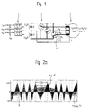
- the inverter 1 is a schematic illustration showing a powered from a three-phase pulse-controlled inverter 1 electric machine 2.
- the inverter 1 comprises six disconnectable elements 3.
- the voltages u a, b, c are the inverter output voltages, u 1a, b, c the stator voltages, u 0 the star zero point voltage and U d the input DC voltage.
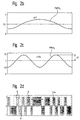
- FIG. 2a shows a diagram with the voltage profiles of a modulation signal u Sta and the carrier signal u H.
- the intersections of the signals u Sta and u H result in the switching times 5 of the switching elements 3.
- the inverter output voltage u a changes the polarity.
- the modulation level a 0 (modulation index) and the fundamental frequency f 1 of the modulation signals u Sta, b, c determine the amplitude a 0 . (U d / 2) and the frequency f 1 of the fundamental oscillation u GS of the inverter output voltages U a, b, c .
- F 0 is the basic clock frequency
- ⁇ F the frequency deviation of the pulse frequency modulation (PFM)
- f F the PFM frequency
- ⁇ F the phase position of the sinusoidally varied clock frequency.
- 2b shows a diagram with the profile of the sinusoidal PWM signal u Sta with the fundamental oscillation frequency f 1 .
- u Sta, b, c U St ⁇ Cos (2 ⁇ ⁇ ⁇ f 1 + ⁇ 0 + D)
- FIG. 2c shows the course of the sinusoidal PFM signal with the frequency f F , which modulates the triangular carrier signal u H.
- the aim of modulating the carrier signal u H is to influence the frequency spectrum of the inverter output voltages u a, b, c by continuously changing the inverter switching frequency F so that a uniform frequency distribution is produced. It is also possible to modulate the triangular carrier signal u H with other waveforms, such as triangular, sawtooth, etc.
- Figure 2d shows an explanatory image of a possible course of an inverter output voltage u a. The edges of the voltage blocks 6 correspond to the switching times 5.
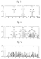
- FIG. 3 shows a frequency spectrum of a stator voltage generated with the undershoot method.
- the generated voltage u a has high amplitudes due to the constant clock frequency F of the carrier signal u H only at individual frequencies by multiples of the clock frequency F. These harmonics produce a sharp, unpleasant sound.
- FIG. 4 shows an explanatory picture of a frequency spectrum of a stator voltage with additional sinusoidal pulse frequency modulation (PFM) of the carrier signal u H.
- the constant change in the frequency F of the triangular carrier signal u H results in a uniform distribution of the harmonics over the entire frequency range.
- the main groups of the harmonics of the undershoot method with a constant carrier frequency are fanned out with the parameters n and v into subgroups of the method according to the invention with the parameters n, m and v, where n is the ordinal number of the basic clock frequency F 0 , v the ordinal number of the PWM frequency f 1 and m is the atomic number of the PFM frequency f F.
- FIG. 5 shows a broadly diversified frequency spectrum of a stator voltage using the method according to the invention.
- the following formula can be used to calculate the inverter output voltages u a, b, c and the harmonic components U nmv : the harmonic components are:
- the frequency spectrum can be changed as desired without influencing the fundamental oscillation u GS .
- the Bessel functions J m (n ⁇ ⁇ F / f F ) J v (n ⁇ ⁇ / 2 ⁇ a 0 ) or the relationship ⁇ F / f F determine the amplitudes U nmv of the harmonic components .
- the greater this ratio the greater the number of subgroups with the atomic number m, and consequently this means a broader distribution of the frequency spectrum.
- This knowledge has the great advantage that the frequency spectrum can be shaped as desired.
- the modulation parameters f F and ⁇ F can be set so that the frequencies of the harmonics U nmv of adjacent main groups n that overlap in the frequency spectrum do not coincide.
- the Bessel function for calculating the harmonics U nmv not only can the frequency spectrum be broadly fanned out, but harmonics of the subgroups m, which would excite mechanical stator resonances, can also be eliminated.
- the PFM frequency f F directly determines the distance ⁇ m ⁇ f F ⁇ v ⁇ f 1 the sideband frequencies to the harmonics n ⁇ F 0 the basic clock frequency F 0 .
- the harmonic amplitudes of the inverter output voltages are reduced, on the one hand, and on the other hand, a sound image is created that no longer has any striking individual frequencies, but is perceived as uniform noise. Not only is there a reduction in the noise level in terms of value, but the occurrence of many frequencies distributed over the entire spectrum also results in a more pleasant noise.
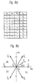
- Fig. 6 shows the course of the optimization of the Modulation method and for the elimination of Bessel functions used frequency bands.
- FIG. 7 shows a section of a frequency spectrum according to the method according to the invention with an eliminated frequency band.
- the elimination is based on the use of Bessel functions.
- the frequencies to be eliminated can be determined by the ratio ⁇ F / f F be determined.
- the amplitudes of the harmonics U nmv with the frequencies n ⁇ F 0 ⁇ m ⁇ f F ⁇ v ⁇ f 1 are proportional to the Bessel function J m (n ⁇ ⁇ F / f F )
- the basic clock frequency F 0 of the triangular carrier signal u H is determined.
- the position of the subgroups m is known from the choice of the PFM frequency f F.
- the disturbing frequency range can be selected on the basis of the determined mechanical stator resonance frequency.
- the ordinal number of the Bessel function can be determined by the ordinal number m of the subgroup. In order to eliminate the frequency band or subgroup m, the Bessel function according to FIG. 6 of the previously determined atomic number must be set to zero. The argument at the zero is equal to the ratio (n ⁇ ⁇ F) / f F
- the PFM frequency f F was previously determined.
- the frequency deviation ⁇ F of the pulse frequency modulation can thus be determined, so that the desired subgroup m is not generated in the frequency spectrum.
- the elimination of the selected sub-group m is independent of the degree of modulation a 0 and the fundamental frequency f 1 and is therefore also independent of the operating point of the machine.
- the second embodiment relates to Procedure using space vector modulation instead of Carrier modulation.
- control voltages u Sta, b, c and the inverter output voltages u a, b, c are transformed into the rotating pointer area using the following rule:
- the "rotary pointer star" shown in FIG. 8b is divided into the labeled sectors I to VI.
Landscapes
- Engineering & Computer Science (AREA)
- Power Engineering (AREA)
- Inverter Devices (AREA)
- Control Of Ac Motors In General (AREA)
- Control Of Multiple Motors (AREA)
- Control Of Electric Motors In General (AREA)
- Control Of Direct Current Motors (AREA)
- Endoscopes (AREA)
- Ultra Sonic Daignosis Equipment (AREA)
- Lighting Device Outwards From Vehicle And Optical Signal (AREA)
Claims (4)
- Procédé pour le fonctionnement peu bruyant d'une machine (2) alimentée par un onduleur à impulsions (1), selon lequel les impulsions de commutation pour la commande des éléments de circuit (3) de l'onduleur (1) grâce auxquelles le modèle d'impulsions de la tension de sortie de l'onduleur (ua,b,c) est formé sont générées par modulation porteuse, la fréquence (F) d'un signal porteur (uH) de la modulation porteuse pour générer le modèle d'impulsions étant modulée à l'aide d'une modulation de fréquence par impulsions (PFM) suivant une fonction définie, pour réduire ou supprimer les harmoniques audibles et gênants de la tension de sortie d'onduleur (ua,b,c),
caractérisé en ce que les parts d'harmoniques (Unmv) de la tension de sortie d'onduleur (ua,b,c) qui doivent être supprimées sont définies mathématiquement en fonction des paramètres constitués par la déviation de fréquence (ΔF) et la fréquence (fF) de la modulation de fréquence par impulsions (PFM). - Procédé selon la revendication 1, caractérisé en ce que les parts d'harmoniques (Unmv) de la tension de sortie d'onduleur (ua,b,c) dépendent d'une fonction de Bessel avec comme argument le rapport (nΔF/fF) des paramètres de modulation.
- Procédé selon la revendication 2, caractérisé en ce que grâce à une augmentation du rapport (nΔF/fF), l'étendue du spectre de fréquences dans des sous-groupes (m) augmente et les amplitudes des harmoniques (Unmv) diminuent.
- Procédé selon la revendication 2 ou 3, caractérisé en ce qu'on peut supprimer des sous-groupes (m) dans le spectre de fréquences en fixant le rapport (nΔF/fF) des paramètres de modulation de telle sorte que la fonction de Bessel Jm(nΔF/fF) qui appartient au sous-groupe (m) devienne nulle.
Priority Applications (10)
| Application Number | Priority Date | Filing Date | Title |
|---|---|---|---|
| EP94108512A EP0685923B1 (fr) | 1994-06-03 | 1994-06-03 | Opération peu bruyante d'un moteur alimenté par un onduleur à impulsions |
| AT94108512T ATE183860T1 (de) | 1994-06-03 | 1994-06-03 | Geräuscharmer betrieb einer von einem pulswechselrichter gespeisten maschine |
| DE59408662T DE59408662D1 (de) | 1994-06-03 | 1994-06-03 | Geräuscharmer Betrieb einer von einem Pulswechselrichter gespeisten Maschine |
| CA002149112A CA2149112A1 (fr) | 1994-06-03 | 1995-05-09 | Fonctionnement a faible bruit d'une machine alimentee par un inverseur d'impulsions |
| US08/449,306 US5625542A (en) | 1994-06-03 | 1995-05-24 | Low-noise operation of a machine fed by a pulse inverter |
| FI952639A FI952639A (fi) | 1994-06-03 | 1995-05-31 | Pulssivaihtosuuntaajan syöttämän koneen vähä-ääninen käyttö |
| CN95107184A CN1042278C (zh) | 1994-06-03 | 1995-06-02 | 一种机器的低噪音操作的方法 |
| JP7136876A JPH07337089A (ja) | 1994-06-03 | 1995-06-02 | パルス・インバータで給電される機械の低ノイズ運転 |
| BR9502659A BR9502659A (pt) | 1994-06-03 | 1995-06-05 | Processo para a operação silenciosa de um motor que é alimentado por inversor de pulsos |
| HK98113558A HK1018581A1 (en) | 1994-06-03 | 1998-12-16 | Low-noise operation of a machine fed by a pulse inverter |
Applications Claiming Priority (1)
| Application Number | Priority Date | Filing Date | Title |
|---|---|---|---|
| EP94108512A EP0685923B1 (fr) | 1994-06-03 | 1994-06-03 | Opération peu bruyante d'un moteur alimenté par un onduleur à impulsions |
Publications (2)
| Publication Number | Publication Date |
|---|---|
| EP0685923A1 EP0685923A1 (fr) | 1995-12-06 |
| EP0685923B1 true EP0685923B1 (fr) | 1999-08-25 |
Family
ID=8215989
Family Applications (1)
| Application Number | Title | Priority Date | Filing Date |
|---|---|---|---|
| EP94108512A Revoked EP0685923B1 (fr) | 1994-06-03 | 1994-06-03 | Opération peu bruyante d'un moteur alimenté par un onduleur à impulsions |
Country Status (10)
| Country | Link |
|---|---|
| US (1) | US5625542A (fr) |
| EP (1) | EP0685923B1 (fr) |
| JP (1) | JPH07337089A (fr) |
| CN (1) | CN1042278C (fr) |
| AT (1) | ATE183860T1 (fr) |
| BR (1) | BR9502659A (fr) |
| CA (1) | CA2149112A1 (fr) |
| DE (1) | DE59408662D1 (fr) |
| FI (1) | FI952639A (fr) |
| HK (1) | HK1018581A1 (fr) |
Cited By (2)
| Publication number | Priority date | Publication date | Assignee | Title |
|---|---|---|---|---|
| WO2011117278A1 (fr) | 2010-03-25 | 2011-09-29 | Siemens Aktiengesellschaft | Procédé pour faire fonctionner un moteur de propulsion d'un navire alimenté par au moins un convertisseur commandé par modulation de largeurs d'impulsions, et système de propulsion de navire correspondant |
| DE102016014093A1 (de) | 2016-07-01 | 2018-01-04 | Sew-Eurodrive Gmbh & Co Kg | Verfahren zum Betreiben eines Antriebs mit Wechselrichter, insbesondere eines Umrichters und Antrieb mit Wechselrichter |
Families Citing this family (29)
| Publication number | Priority date | Publication date | Assignee | Title |
|---|---|---|---|---|
| US6144176A (en) * | 1996-10-02 | 2000-11-07 | Lucent Technologies Inc. | Method for reducing acoustic and vibration energy radiated from rotating machines |
| DE19651281C2 (de) * | 1996-12-10 | 1999-11-04 | Still Gmbh | Modulationsverfahren zur Steuerung eines Wechselrichters |
| US6069808A (en) * | 1997-05-21 | 2000-05-30 | Texas Instruments Incorporated | Symmetrical space vector PWM DC-AC converter controller |
| JP3708292B2 (ja) * | 1997-06-17 | 2005-10-19 | 三菱電機株式会社 | Pwmインバータ装置の制御方法および制御装置 |
| DE60043893D1 (de) | 1999-09-16 | 2010-04-08 | Delphi Tech Inc | Vrefahren und gerät zur drehmoment-linearisierung in einem servolenkungssystem |
| JP2003513594A (ja) | 1999-09-16 | 2003-04-08 | デルファイ・テクノロジーズ・インコーポレーテッド | 不均衡状態に起因するモータトルクリップルの最小化 |
| US6674789B1 (en) | 1999-09-17 | 2004-01-06 | Delphi Technologies, Inc. | Reduction of EMI through switching frequency dithering |
| US6694287B2 (en) | 2001-08-30 | 2004-02-17 | Delphi Technologies, Inc. | Phase angle diagnostics for sinusoidal controlled electric machine |
| US20030062868A1 (en) * | 2001-10-01 | 2003-04-03 | Mir Sayeed A. | Switching methodology for ground referenced voltage controlled electric machine |
| US6762577B2 (en) | 2001-11-14 | 2004-07-13 | General Electric Company | DC motor speed control system |
| AU2003256296B2 (en) * | 2002-07-31 | 2008-04-03 | Smc Electrical Products, Inc. | Low voltage, two-level, six-pulse induction motor controller driving a medium-to-high voltage, three-or-more-level AC drive inverter bridge |
| CA2422413C (fr) * | 2003-03-17 | 2007-10-09 | Precisionh2 Inc. | Inverseur d'onde sinusoidale faisant appel a un regulateur hybride |
| JP4085976B2 (ja) * | 2003-12-25 | 2008-05-14 | 日産自動車株式会社 | インバータの制御装置及び制御方法 |
| JP4239886B2 (ja) * | 2004-04-14 | 2009-03-18 | 株式会社デンソー | 交流回転電機の磁気音制御方法 |
| US7413413B2 (en) * | 2004-07-20 | 2008-08-19 | York International Corporation | System and method to reduce acoustic noise in screw compressors |
| CA2481277A1 (fr) * | 2004-10-07 | 2006-04-07 | Ivan Meszlenyi | Convertisseur de puissance de modulation de temps de transition d'impulsion |
| KR100694622B1 (ko) | 2006-02-24 | 2007-03-13 | 램스웨이 주식회사 | Fm 송신기 |
| JP5239235B2 (ja) * | 2006-10-13 | 2013-07-17 | 日産自動車株式会社 | 電力変換装置および電力変換方法 |
| BRPI0702291A2 (pt) * | 2007-05-17 | 2008-12-30 | Whirlpool Sa | mÉtodo e sistema de reduÇço de interferÊncia eletromagnÉtica em um sistema de refrigeraÇço |
| US7920393B2 (en) * | 2007-06-01 | 2011-04-05 | Drs Power & Control Technologies, Inc. | Four pole neutral-point clamped three phase converter with low common mode voltage output |
| US8292593B2 (en) * | 2009-08-28 | 2012-10-23 | Oracle America, Inc. | System for minimizing mechanical and acoustical fan noise coupling |
| CN102315787B (zh) * | 2010-06-29 | 2014-03-12 | 比亚迪股份有限公司 | 一种开关电源控制电路及开关电源 |
| JP5553288B2 (ja) * | 2011-03-15 | 2014-07-16 | 株式会社豊田自動織機 | 回転電機のインバータ装置、及び回転電機の駆動方法 |
| JP2013192382A (ja) * | 2012-03-14 | 2013-09-26 | Denso Corp | ソーラーパワーコンディショナ |
| DE102012212318A1 (de) * | 2012-07-13 | 2014-01-16 | Oerlikon Leybold Vacuum Gmbh | Verfahren zum Steuern einer Vakuumpumpe |
| DE102018206596A1 (de) * | 2018-04-27 | 2019-12-24 | Siemens Mobility GmbH | Verfahren zum Ansteuern eines Pulswechselrichters, Verwendung, Steuereinheit und stationäres oder mobiles System |
| DE102020211718A1 (de) * | 2020-09-18 | 2022-03-24 | Siemens Aktiengesellschaft | Netzeinspeisewechselrichter |
| CN113364255B (zh) * | 2021-03-09 | 2023-09-01 | 国网浙江省电力有限公司湖州供电公司 | 一种频率交错的换流器单元及控制方法 |
| DE102022107101A1 (de) | 2022-03-25 | 2023-09-28 | Bayerische Motoren Werke Aktiengesellschaft | Verfahren zur Bestimmung einer Rotorlage eines Rotors einer elektrischen Maschine, Steuereinrichtung, elektrische Maschine sowie Kraftfahrzeug |
Family Cites Families (4)
| Publication number | Priority date | Publication date | Assignee | Title |
|---|---|---|---|---|
| EP0163746B1 (fr) * | 1983-11-28 | 1997-04-23 | Matsushita Electric Industrial Co., Ltd. | Dispositif inverseur a modulation par largeur d'impulsions |
| JPS63148894A (ja) * | 1986-12-10 | 1988-06-21 | Mitsubishi Electric Corp | Pwmインバ−タの制御装置 |
| DE3912706A1 (de) * | 1989-04-18 | 1990-10-25 | Siemens Ag | Verfahren zum geraeuscharmen betrieb einer von einem pulswechselrichter gespeisten maschine |
| JPH0382396A (ja) * | 1989-08-23 | 1991-04-08 | Mitsubishi Electric Corp | パルス幅変調形インバータ装置 |
-
1994
- 1994-06-03 DE DE59408662T patent/DE59408662D1/de not_active Revoked
- 1994-06-03 EP EP94108512A patent/EP0685923B1/fr not_active Revoked
- 1994-06-03 AT AT94108512T patent/ATE183860T1/de not_active IP Right Cessation
-
1995
- 1995-05-09 CA CA002149112A patent/CA2149112A1/fr not_active Abandoned
- 1995-05-24 US US08/449,306 patent/US5625542A/en not_active Expired - Fee Related
- 1995-05-31 FI FI952639A patent/FI952639A/fi unknown
- 1995-06-02 JP JP7136876A patent/JPH07337089A/ja active Pending
- 1995-06-02 CN CN95107184A patent/CN1042278C/zh not_active Expired - Fee Related
- 1995-06-05 BR BR9502659A patent/BR9502659A/pt not_active Application Discontinuation
-
1998
- 1998-12-16 HK HK98113558A patent/HK1018581A1/xx not_active IP Right Cessation
Cited By (2)
| Publication number | Priority date | Publication date | Assignee | Title |
|---|---|---|---|---|
| WO2011117278A1 (fr) | 2010-03-25 | 2011-09-29 | Siemens Aktiengesellschaft | Procédé pour faire fonctionner un moteur de propulsion d'un navire alimenté par au moins un convertisseur commandé par modulation de largeurs d'impulsions, et système de propulsion de navire correspondant |
| DE102016014093A1 (de) | 2016-07-01 | 2018-01-04 | Sew-Eurodrive Gmbh & Co Kg | Verfahren zum Betreiben eines Antriebs mit Wechselrichter, insbesondere eines Umrichters und Antrieb mit Wechselrichter |
Also Published As
| Publication number | Publication date |
|---|---|
| BR9502659A (pt) | 1996-01-02 |
| FI952639A0 (fi) | 1995-05-31 |
| CN1042278C (zh) | 1999-02-24 |
| HK1018581A1 (en) | 1999-12-24 |
| CN1115919A (zh) | 1996-01-31 |
| US5625542A (en) | 1997-04-29 |
| JPH07337089A (ja) | 1995-12-22 |
| DE59408662D1 (de) | 1999-09-30 |
| ATE183860T1 (de) | 1999-09-15 |
| CA2149112A1 (fr) | 1995-12-04 |
| FI952639A (fi) | 1995-12-04 |
| EP0685923A1 (fr) | 1995-12-06 |
Similar Documents
| Publication | Publication Date | Title |
|---|---|---|
| EP0685923B1 (fr) | Opération peu bruyante d'un moteur alimenté par un onduleur à impulsions | |
| DE69835853T2 (de) | Verfahren und Vorrichtung zur Steuerung eines pulsbreitenmodulierten Wechselrichters | |
| DE102005053246B4 (de) | Steuerung einer durch ein Pulsbreitenmodulationssignal angesteuerten Vorrichtung und Verfahren um Geräusch der Vorrichtung zu reduzieren | |
| DE3439893C2 (fr) | ||
| EP0151296A2 (fr) | Circuit de commande pour un moteur pas à pas | |
| EP0958651B1 (fr) | Procede et dispositif de commande de moteur pas-a-pas | |
| DE3446307A1 (de) | Verfahren und schaltungsanordnung zur erzeugung von sinusschwingungen | |
| EP0832514B1 (fr) | Procede de commande d'un moteur pas a pas | |
| DE1538223A1 (de) | Verfahren zur Erzeugung eines Mehrphasen-Sinusstromes veraenderbarer Frequenz,Geraet zur Ausfuehrung dieses Verfahrens und Anwendung dieses Verfahrens zur Steuerung eines eine elektrische Asynchronmaschine speisenden Stromrichters | |
| DE19721282A1 (de) | Verfahren zum Treiben eines Schrittmotors | |
| DE102017208769A1 (de) | Verfahren und Vorrichtung zur Beeinflussung der akustischen Abstrahlung einer elektrischen Maschine eines Kraftfahrzeuges | |
| DE2747964C2 (de) | Steuerverfahren für einen dreiphasigen selbstgeführten Wechselrichter | |
| DE3204266C2 (fr) | ||
| DE3313445C2 (fr) | ||
| WO1991003862A1 (fr) | Dispositif et procede pour le fonctionnement optimise d'un convertisseur relie a un reseau | |
| DE2220838A1 (de) | Frequenzabhaengiger mehrphasiger Impulsgenerator | |
| EP0363514A1 (fr) | Méthode de contrôle d'un circuit utilisateur à courant triphasé par modulation d'impulsions en largeur estimant une sinusoide | |
| EP0544728B1 (fr) | Generateur de tensions a amplitudes couplees | |
| EP1063762B1 (fr) | Méthode de positionnement d'un moteur pas-à-pas et entraínement électrique | |
| EP0829950B1 (fr) | Oscillateur contrÔlé numériquement | |
| EP0004042B1 (fr) | Ensemble de circuits pour l'obtention de fréquences porteuses | |
| DE3320006C2 (fr) | ||
| DE102021115635A1 (de) | Elektrische Maschine mit selektiver akustischer Anregung und Kraftfahrzeug | |
| DE102022212018A1 (de) | Verfahren und Vorrichtung zur Ansteuerung eines Stromrichters | |
| DE2436201C3 (de) | Verfahren zum Antrieb eines elektrischen Schrittmotors und Schaltungsanordnung zur Durchführung des Verfahrens |
Legal Events
| Date | Code | Title | Description |
|---|---|---|---|
| PUAI | Public reference made under article 153(3) epc to a published international application that has entered the european phase |
Free format text: ORIGINAL CODE: 0009012 |
|
| AK | Designated contracting states |
Kind code of ref document: A1 Designated state(s): AT CH DE ES FR GB LI |
|
| RAX | Requested extension states of the european patent have changed |
Free format text: SI |
|
| RBV | Designated contracting states (corrected) |
Designated state(s): AT CH DE ES FR GB LI |
|
| 17P | Request for examination filed |
Effective date: 19960517 |
|
| 17Q | First examination report despatched |
Effective date: 19961127 |
|
| GRAG | Despatch of communication of intention to grant |
Free format text: ORIGINAL CODE: EPIDOS AGRA |
|
| GRAG | Despatch of communication of intention to grant |
Free format text: ORIGINAL CODE: EPIDOS AGRA |
|
| GRAH | Despatch of communication of intention to grant a patent |
Free format text: ORIGINAL CODE: EPIDOS IGRA |
|
| GRAH | Despatch of communication of intention to grant a patent |
Free format text: ORIGINAL CODE: EPIDOS IGRA |
|
| GRAA | (expected) grant |
Free format text: ORIGINAL CODE: 0009210 |
|
| AK | Designated contracting states |
Kind code of ref document: B1 Designated state(s): AT CH DE ES FR GB LI |
|
| PG25 | Lapsed in a contracting state [announced via postgrant information from national office to epo] |
Ref country code: FR Free format text: LAPSE BECAUSE OF FAILURE TO SUBMIT A TRANSLATION OF THE DESCRIPTION OR TO PAY THE FEE WITHIN THE PRESCRIBED TIME-LIMIT Effective date: 19990825 Ref country code: ES Free format text: THE PATENT HAS BEEN ANNULLED BY A DECISION OF A NATIONAL AUTHORITY Effective date: 19990825 |
|
| REF | Corresponds to: |
Ref document number: 183860 Country of ref document: AT Date of ref document: 19990915 Kind code of ref document: T |
|
| REG | Reference to a national code |
Ref country code: CH Ref legal event code: EP |
|
| REF | Corresponds to: |
Ref document number: 59408662 Country of ref document: DE Date of ref document: 19990930 |
|
| GBT | Gb: translation of ep patent filed (gb section 77(6)(a)/1977) |
Effective date: 19990921 |
|
| EN | Fr: translation not filed | ||
| PLBQ | Unpublished change to opponent data |
Free format text: ORIGINAL CODE: EPIDOS OPPO |
|
| PLBI | Opposition filed |
Free format text: ORIGINAL CODE: 0009260 |
|
| PG25 | Lapsed in a contracting state [announced via postgrant information from national office to epo] |
Ref country code: AT Free format text: LAPSE BECAUSE OF NON-PAYMENT OF DUE FEES Effective date: 20000603 |
|
| PLBF | Reply of patent proprietor to notice(s) of opposition |
Free format text: ORIGINAL CODE: EPIDOS OBSO |
|
| 26 | Opposition filed |
Opponent name: LINDE AKTIENGESELLSCHAFT Effective date: 20000523 |
|
| PLBF | Reply of patent proprietor to notice(s) of opposition |
Free format text: ORIGINAL CODE: EPIDOS OBSO |
|
| REG | Reference to a national code |
Ref country code: GB Ref legal event code: IF02 |
|
| PGFP | Annual fee paid to national office [announced via postgrant information from national office to epo] |
Ref country code: GB Payment date: 20020614 Year of fee payment: 9 |
|
| PGFP | Annual fee paid to national office [announced via postgrant information from national office to epo] |
Ref country code: DE Payment date: 20020619 Year of fee payment: 9 |
|
| PGFP | Annual fee paid to national office [announced via postgrant information from national office to epo] |
Ref country code: CH Payment date: 20020918 Year of fee payment: 9 |
|
| RDAH | Patent revoked |
Free format text: ORIGINAL CODE: EPIDOS REVO |
|
| RDAG | Patent revoked |
Free format text: ORIGINAL CODE: 0009271 |
|
| STAA | Information on the status of an ep patent application or granted ep patent |
Free format text: STATUS: PATENT REVOKED |
|
| 27W | Patent revoked |
Effective date: 20030523 |
|
| GBPR | Gb: patent revoked under art. 102 of the ep convention designating the uk as contracting state |
Free format text: 20030523 |
|
| REG | Reference to a national code |
Ref country code: CH Ref legal event code: PL |