EP0683890B1 - Procede et dispositif pour corriger la derive du decalage d'un capteur de pression d'un debitmetre - Google Patents
Procede et dispositif pour corriger la derive du decalage d'un capteur de pression d'un debitmetre Download PDFInfo
- Publication number
- EP0683890B1 EP0683890B1 EP94907924A EP94907924A EP0683890B1 EP 0683890 B1 EP0683890 B1 EP 0683890B1 EP 94907924 A EP94907924 A EP 94907924A EP 94907924 A EP94907924 A EP 94907924A EP 0683890 B1 EP0683890 B1 EP 0683890B1
- Authority
- EP
- European Patent Office
- Prior art keywords
- digital
- flow
- value
- zero
- analog
- Prior art date
- Legal status (The legal status is an assumption and is not a legal conclusion. Google has not performed a legal analysis and makes no representation as to the accuracy of the status listed.)
- Expired - Lifetime
Links
- 238000000034 method Methods 0.000 title claims description 25
- 239000000872 buffer Substances 0.000 claims description 30
- 238000005070 sampling Methods 0.000 claims description 9
- 229940079593 drug Drugs 0.000 description 94
- 239000003814 drug Substances 0.000 description 94
- 239000000443 aerosol Substances 0.000 description 50
- 230000003434 inspiratory effect Effects 0.000 description 38
- 230000007246 mechanism Effects 0.000 description 32
- 238000007906 compression Methods 0.000 description 30
- 230000006835 compression Effects 0.000 description 30
- 230000009325 pulmonary function Effects 0.000 description 28
- 238000005259 measurement Methods 0.000 description 14
- 239000000463 material Substances 0.000 description 12
- 230000004044 response Effects 0.000 description 12
- 230000000994 depressogenic effect Effects 0.000 description 9
- 238000003780 insertion Methods 0.000 description 9
- 230000037431 insertion Effects 0.000 description 9
- 230000033001 locomotion Effects 0.000 description 9
- 230000008569 process Effects 0.000 description 9
- 238000010304 firing Methods 0.000 description 8
- 238000002483 medication Methods 0.000 description 8
- 238000003825 pressing Methods 0.000 description 8
- 229940071648 metered dose inhaler Drugs 0.000 description 7
- 238000012545 processing Methods 0.000 description 7
- 150000001875 compounds Chemical class 0.000 description 6
- 230000000694 effects Effects 0.000 description 6
- 239000002184 metal Substances 0.000 description 6
- 239000000203 mixture Substances 0.000 description 6
- 241000282472 Canis lupus familiaris Species 0.000 description 5
- 230000008859 change Effects 0.000 description 5
- 238000010276 construction Methods 0.000 description 5
- 238000013461 design Methods 0.000 description 5
- 230000002829 reductive effect Effects 0.000 description 5
- 230000035945 sensitivity Effects 0.000 description 5
- 230000008901 benefit Effects 0.000 description 4
- 238000012937 correction Methods 0.000 description 4
- 230000001419 dependent effect Effects 0.000 description 4
- 238000009826 distribution Methods 0.000 description 4
- 238000000605 extraction Methods 0.000 description 4
- 230000006870 function Effects 0.000 description 4
- 239000002245 particle Substances 0.000 description 4
- 239000000843 powder Substances 0.000 description 4
- 239000003380 propellant Substances 0.000 description 4
- 230000000007 visual effect Effects 0.000 description 4
- 230000009471 action Effects 0.000 description 3
- 238000013459 approach Methods 0.000 description 3
- 238000006243 chemical reaction Methods 0.000 description 3
- 238000004891 communication Methods 0.000 description 3
- 230000000881 depressing effect Effects 0.000 description 3
- 238000009472 formulation Methods 0.000 description 3
- 239000007789 gas Substances 0.000 description 3
- 238000002372 labelling Methods 0.000 description 3
- 239000007788 liquid Substances 0.000 description 3
- 238000012544 monitoring process Methods 0.000 description 3
- -1 polypropylene Polymers 0.000 description 3
- 238000012360 testing method Methods 0.000 description 3
- 238000002560 therapeutic procedure Methods 0.000 description 3
- 238000012546 transfer Methods 0.000 description 3
- 229920004943 Delrin® Polymers 0.000 description 2
- 239000004743 Polypropylene Substances 0.000 description 2
- 238000013019 agitation Methods 0.000 description 2
- 238000003491 array Methods 0.000 description 2
- 230000006399 behavior Effects 0.000 description 2
- 210000000038 chest Anatomy 0.000 description 2
- 238000004140 cleaning Methods 0.000 description 2
- 230000003750 conditioning effect Effects 0.000 description 2
- 230000001186 cumulative effect Effects 0.000 description 2
- 230000000593 degrading effect Effects 0.000 description 2
- 238000010586 diagram Methods 0.000 description 2
- 238000012377 drug delivery Methods 0.000 description 2
- 239000008240 homogeneous mixture Substances 0.000 description 2
- 230000006872 improvement Effects 0.000 description 2
- 238000007373 indentation Methods 0.000 description 2
- 230000007774 longterm Effects 0.000 description 2
- 239000003595 mist Substances 0.000 description 2
- 239000004033 plastic Substances 0.000 description 2
- 229920003023 plastic Polymers 0.000 description 2
- 229920001155 polypropylene Polymers 0.000 description 2
- 239000002243 precursor Substances 0.000 description 2
- 230000001960 triggered effect Effects 0.000 description 2
- DHKHKXVYLBGOIT-UHFFFAOYSA-N 1,1-Diethoxyethane Chemical compound CCOC(C)OCC DHKHKXVYLBGOIT-UHFFFAOYSA-N 0.000 description 1
- VYZAMTAEIAYCRO-UHFFFAOYSA-N Chromium Chemical compound [Cr] VYZAMTAEIAYCRO-UHFFFAOYSA-N 0.000 description 1
- 241001076195 Lampsilis ovata Species 0.000 description 1
- 206010033296 Overdoses Diseases 0.000 description 1
- 229910000639 Spring steel Inorganic materials 0.000 description 1
- 208000005279 Status Asthmaticus Diseases 0.000 description 1
- 239000004809 Teflon Substances 0.000 description 1
- 229920006362 Teflon® Polymers 0.000 description 1
- 229910001315 Tool steel Inorganic materials 0.000 description 1
- 230000002159 abnormal effect Effects 0.000 description 1
- 239000011354 acetal resin Substances 0.000 description 1
- 230000002411 adverse Effects 0.000 description 1
- 230000000903 blocking effect Effects 0.000 description 1
- 229940124630 bronchodilator Drugs 0.000 description 1
- 230000003247 decreasing effect Effects 0.000 description 1
- 238000001514 detection method Methods 0.000 description 1
- 239000006185 dispersion Substances 0.000 description 1
- 230000009429 distress Effects 0.000 description 1
- 238000002651 drug therapy Methods 0.000 description 1
- 230000005611 electricity Effects 0.000 description 1
- 238000005265 energy consumption Methods 0.000 description 1
- 229920002457 flexible plastic Polymers 0.000 description 1
- 230000010006 flight Effects 0.000 description 1
- 239000012530 fluid Substances 0.000 description 1
- 239000002783 friction material Substances 0.000 description 1
- 230000010354 integration Effects 0.000 description 1
- 230000003993 interaction Effects 0.000 description 1
- 239000004973 liquid crystal related substance Substances 0.000 description 1
- 238000004519 manufacturing process Methods 0.000 description 1
- 238000013507 mapping Methods 0.000 description 1
- 238000012986 modification Methods 0.000 description 1
- 230000004048 modification Effects 0.000 description 1
- 230000003533 narcotic effect Effects 0.000 description 1
- 230000036961 partial effect Effects 0.000 description 1
- 238000007747 plating Methods 0.000 description 1
- 229920006324 polyoxymethylene Polymers 0.000 description 1
- 230000002685 pulmonary effect Effects 0.000 description 1
- 238000009613 pulmonary function test Methods 0.000 description 1
- 230000000452 restraining effect Effects 0.000 description 1
- 230000002441 reversible effect Effects 0.000 description 1
- 238000000926 separation method Methods 0.000 description 1
- 150000003431 steroids Chemical class 0.000 description 1
- 238000003860 storage Methods 0.000 description 1
- 230000001225 therapeutic effect Effects 0.000 description 1
- 230000001052 transient effect Effects 0.000 description 1
- 230000007704 transition Effects 0.000 description 1
- XLYOFNOQVPJJNP-UHFFFAOYSA-N water Substances O XLYOFNOQVPJJNP-UHFFFAOYSA-N 0.000 description 1
Images


Classifications
-
- A—HUMAN NECESSITIES
- A61—MEDICAL OR VETERINARY SCIENCE; HYGIENE
- A61M—DEVICES FOR INTRODUCING MEDIA INTO, OR ONTO, THE BODY; DEVICES FOR TRANSDUCING BODY MEDIA OR FOR TAKING MEDIA FROM THE BODY; DEVICES FOR PRODUCING OR ENDING SLEEP OR STUPOR
- A61M15/00—Inhalators
-
- A—HUMAN NECESSITIES
- A61—MEDICAL OR VETERINARY SCIENCE; HYGIENE
- A61M—DEVICES FOR INTRODUCING MEDIA INTO, OR ONTO, THE BODY; DEVICES FOR TRANSDUCING BODY MEDIA OR FOR TAKING MEDIA FROM THE BODY; DEVICES FOR PRODUCING OR ENDING SLEEP OR STUPOR
- A61M15/00—Inhalators
- A61M15/0001—Details of inhalators; Constructional features thereof
- A61M15/0021—Mouthpieces therefor
-
- A—HUMAN NECESSITIES
- A61—MEDICAL OR VETERINARY SCIENCE; HYGIENE
- A61M—DEVICES FOR INTRODUCING MEDIA INTO, OR ONTO, THE BODY; DEVICES FOR TRANSDUCING BODY MEDIA OR FOR TAKING MEDIA FROM THE BODY; DEVICES FOR PRODUCING OR ENDING SLEEP OR STUPOR
- A61M15/00—Inhalators
- A61M15/0065—Inhalators with dosage or measuring devices
- A61M15/0068—Indicating or counting the number of dispensed doses or of remaining doses
- A61M15/008—Electronic counters
-
- A—HUMAN NECESSITIES
- A61—MEDICAL OR VETERINARY SCIENCE; HYGIENE
- A61M—DEVICES FOR INTRODUCING MEDIA INTO, OR ONTO, THE BODY; DEVICES FOR TRANSDUCING BODY MEDIA OR FOR TAKING MEDIA FROM THE BODY; DEVICES FOR PRODUCING OR ENDING SLEEP OR STUPOR
- A61M16/00—Devices for influencing the respiratory system of patients by gas treatment, e.g. mouth-to-mouth respiration; Tracheal tubes
- A61M16/08—Bellows; Connecting tubes ; Water traps; Patient circuits
- A61M16/0816—Joints or connectors
- A61M16/0841—Joints or connectors for sampling
- A61M16/0858—Pressure sampling ports
-
- A—HUMAN NECESSITIES
- A61—MEDICAL OR VETERINARY SCIENCE; HYGIENE
- A61M—DEVICES FOR INTRODUCING MEDIA INTO, OR ONTO, THE BODY; DEVICES FOR TRANSDUCING BODY MEDIA OR FOR TAKING MEDIA FROM THE BODY; DEVICES FOR PRODUCING OR ENDING SLEEP OR STUPOR
- A61M16/00—Devices for influencing the respiratory system of patients by gas treatment, e.g. mouth-to-mouth respiration; Tracheal tubes
- A61M16/20—Valves specially adapted to medical respiratory devices
- A61M16/201—Controlled valves
- A61M16/202—Controlled valves electrically actuated
-
- B—PERFORMING OPERATIONS; TRANSPORTING
- B01—PHYSICAL OR CHEMICAL PROCESSES OR APPARATUS IN GENERAL
- B01F—MIXING, e.g. DISSOLVING, EMULSIFYING OR DISPERSING
- B01F23/00—Mixing according to the phases to be mixed, e.g. dispersing or emulsifying
- B01F23/20—Mixing gases with liquids
- B01F23/21—Mixing gases with liquids by introducing liquids into gaseous media
- B01F23/213—Mixing gases with liquids by introducing liquids into gaseous media by spraying or atomising of the liquids
- B01F23/2132—Mixing gases with liquids by introducing liquids into gaseous media by spraying or atomising of the liquids using nozzles
-
- B—PERFORMING OPERATIONS; TRANSPORTING
- B01—PHYSICAL OR CHEMICAL PROCESSES OR APPARATUS IN GENERAL
- B01F—MIXING, e.g. DISSOLVING, EMULSIFYING OR DISPERSING
- B01F35/00—Accessories for mixers; Auxiliary operations or auxiliary devices; Parts or details of general application
- B01F35/71—Feed mechanisms
- B01F35/714—Feed mechanisms for feeding predetermined amounts
-
- B—PERFORMING OPERATIONS; TRANSPORTING
- B01—PHYSICAL OR CHEMICAL PROCESSES OR APPARATUS IN GENERAL
- B01F—MIXING, e.g. DISSOLVING, EMULSIFYING OR DISPERSING
- B01F35/00—Accessories for mixers; Auxiliary operations or auxiliary devices; Parts or details of general application
- B01F35/71—Feed mechanisms
- B01F35/717—Feed mechanisms characterised by the means for feeding the components to the mixer
- B01F35/7179—Feed mechanisms characterised by the means for feeding the components to the mixer using sprayers, nozzles or jets
-
- B—PERFORMING OPERATIONS; TRANSPORTING
- B01—PHYSICAL OR CHEMICAL PROCESSES OR APPARATUS IN GENERAL
- B01F—MIXING, e.g. DISSOLVING, EMULSIFYING OR DISPERSING
- B01F35/00—Accessories for mixers; Auxiliary operations or auxiliary devices; Parts or details of general application
- B01F35/75—Discharge mechanisms
- B01F35/754—Discharge mechanisms characterised by the means for discharging the components from the mixer
- B01F35/7547—Discharge mechanisms characterised by the means for discharging the components from the mixer using valves, gates, orifices or openings
-
- G—PHYSICS
- G01—MEASURING; TESTING
- G01F—MEASURING VOLUME, VOLUME FLOW, MASS FLOW OR LIQUID LEVEL; METERING BY VOLUME
- G01F1/00—Measuring the volume flow or mass flow of fluid or fluent solid material wherein the fluid passes through a meter in a continuous flow
- G01F1/05—Measuring the volume flow or mass flow of fluid or fluent solid material wherein the fluid passes through a meter in a continuous flow by using mechanical effects
- G01F1/34—Measuring the volume flow or mass flow of fluid or fluent solid material wherein the fluid passes through a meter in a continuous flow by using mechanical effects by measuring pressure or differential pressure
- G01F1/36—Measuring the volume flow or mass flow of fluid or fluent solid material wherein the fluid passes through a meter in a continuous flow by using mechanical effects by measuring pressure or differential pressure the pressure or differential pressure being created by the use of flow constriction
- G01F1/363—Measuring the volume flow or mass flow of fluid or fluent solid material wherein the fluid passes through a meter in a continuous flow by using mechanical effects by measuring pressure or differential pressure the pressure or differential pressure being created by the use of flow constriction with electrical or electro-mechanical indication
-
- G—PHYSICS
- G01—MEASURING; TESTING
- G01F—MEASURING VOLUME, VOLUME FLOW, MASS FLOW OR LIQUID LEVEL; METERING BY VOLUME
- G01F1/00—Measuring the volume flow or mass flow of fluid or fluent solid material wherein the fluid passes through a meter in a continuous flow
- G01F1/05—Measuring the volume flow or mass flow of fluid or fluent solid material wherein the fluid passes through a meter in a continuous flow by using mechanical effects
- G01F1/34—Measuring the volume flow or mass flow of fluid or fluent solid material wherein the fluid passes through a meter in a continuous flow by using mechanical effects by measuring pressure or differential pressure
- G01F1/36—Measuring the volume flow or mass flow of fluid or fluent solid material wherein the fluid passes through a meter in a continuous flow by using mechanical effects by measuring pressure or differential pressure the pressure or differential pressure being created by the use of flow constriction
- G01F1/40—Details of construction of the flow constriction devices
-
- G—PHYSICS
- G01—MEASURING; TESTING
- G01F—MEASURING VOLUME, VOLUME FLOW, MASS FLOW OR LIQUID LEVEL; METERING BY VOLUME
- G01F1/00—Measuring the volume flow or mass flow of fluid or fluent solid material wherein the fluid passes through a meter in a continuous flow
- G01F1/05—Measuring the volume flow or mass flow of fluid or fluent solid material wherein the fluid passes through a meter in a continuous flow by using mechanical effects
- G01F1/34—Measuring the volume flow or mass flow of fluid or fluent solid material wherein the fluid passes through a meter in a continuous flow by using mechanical effects by measuring pressure or differential pressure
- G01F1/50—Correcting or compensating means
-
- G—PHYSICS
- G01—MEASURING; TESTING
- G01F—MEASURING VOLUME, VOLUME FLOW, MASS FLOW OR LIQUID LEVEL; METERING BY VOLUME
- G01F13/00—Apparatus for measuring by volume and delivering fluids or fluent solid materials, not provided for in the preceding groups
- G01F13/006—Apparatus for measuring by volume and delivering fluids or fluent solid materials, not provided for in the preceding groups measuring volume in function of time
-
- G—PHYSICS
- G01—MEASURING; TESTING
- G01F—MEASURING VOLUME, VOLUME FLOW, MASS FLOW OR LIQUID LEVEL; METERING BY VOLUME
- G01F15/00—Details of, or accessories for, apparatus of groups G01F1/00 - G01F13/00 insofar as such details or appliances are not adapted to particular types of such apparatus
- G01F15/001—Means for regulating or setting the meter for a predetermined quantity
- G01F15/002—Means for regulating or setting the meter for a predetermined quantity for gases
-
- A—HUMAN NECESSITIES
- A61—MEDICAL OR VETERINARY SCIENCE; HYGIENE
- A61J—CONTAINERS SPECIALLY ADAPTED FOR MEDICAL OR PHARMACEUTICAL PURPOSES; DEVICES OR METHODS SPECIALLY ADAPTED FOR BRINGING PHARMACEUTICAL PRODUCTS INTO PARTICULAR PHYSICAL OR ADMINISTERING FORMS; DEVICES FOR ADMINISTERING FOOD OR MEDICINES ORALLY; BABY COMFORTERS; DEVICES FOR RECEIVING SPITTLE
- A61J7/00—Devices for administering medicines orally, e.g. spoons; Pill counting devices; Arrangements for time indication or reminder for taking medicine
- A61J7/04—Arrangements for time indication or reminder for taking medicine, e.g. programmed dispensers
- A61J7/0409—Arrangements for time indication or reminder for taking medicine, e.g. programmed dispensers with timers
- A61J7/0418—Arrangements for time indication or reminder for taking medicine, e.g. programmed dispensers with timers with electronic history memory
-
- A—HUMAN NECESSITIES
- A61—MEDICAL OR VETERINARY SCIENCE; HYGIENE
- A61M—DEVICES FOR INTRODUCING MEDIA INTO, OR ONTO, THE BODY; DEVICES FOR TRANSDUCING BODY MEDIA OR FOR TAKING MEDIA FROM THE BODY; DEVICES FOR PRODUCING OR ENDING SLEEP OR STUPOR
- A61M15/00—Inhalators
- A61M15/009—Inhalators using medicine packages with incorporated spraying means, e.g. aerosol cans
-
- A—HUMAN NECESSITIES
- A61—MEDICAL OR VETERINARY SCIENCE; HYGIENE
- A61M—DEVICES FOR INTRODUCING MEDIA INTO, OR ONTO, THE BODY; DEVICES FOR TRANSDUCING BODY MEDIA OR FOR TAKING MEDIA FROM THE BODY; DEVICES FOR PRODUCING OR ENDING SLEEP OR STUPOR
- A61M16/00—Devices for influencing the respiratory system of patients by gas treatment, e.g. mouth-to-mouth respiration; Tracheal tubes
- A61M16/0003—Accessories therefor, e.g. sensors, vibrators, negative pressure
- A61M2016/0015—Accessories therefor, e.g. sensors, vibrators, negative pressure inhalation detectors
- A61M2016/0018—Accessories therefor, e.g. sensors, vibrators, negative pressure inhalation detectors electrical
- A61M2016/0021—Accessories therefor, e.g. sensors, vibrators, negative pressure inhalation detectors electrical with a proportional output signal, e.g. from a thermistor
-
- A—HUMAN NECESSITIES
- A61—MEDICAL OR VETERINARY SCIENCE; HYGIENE
- A61M—DEVICES FOR INTRODUCING MEDIA INTO, OR ONTO, THE BODY; DEVICES FOR TRANSDUCING BODY MEDIA OR FOR TAKING MEDIA FROM THE BODY; DEVICES FOR PRODUCING OR ENDING SLEEP OR STUPOR
- A61M16/00—Devices for influencing the respiratory system of patients by gas treatment, e.g. mouth-to-mouth respiration; Tracheal tubes
- A61M16/0003—Accessories therefor, e.g. sensors, vibrators, negative pressure
- A61M2016/003—Accessories therefor, e.g. sensors, vibrators, negative pressure with a flowmeter
- A61M2016/0033—Accessories therefor, e.g. sensors, vibrators, negative pressure with a flowmeter electrical
- A61M2016/0039—Accessories therefor, e.g. sensors, vibrators, negative pressure with a flowmeter electrical in the inspiratory circuit
-
- A—HUMAN NECESSITIES
- A61—MEDICAL OR VETERINARY SCIENCE; HYGIENE
- A61M—DEVICES FOR INTRODUCING MEDIA INTO, OR ONTO, THE BODY; DEVICES FOR TRANSDUCING BODY MEDIA OR FOR TAKING MEDIA FROM THE BODY; DEVICES FOR PRODUCING OR ENDING SLEEP OR STUPOR
- A61M2205/00—General characteristics of the apparatus
- A61M2205/50—General characteristics of the apparatus with microprocessors or computers
-
- A—HUMAN NECESSITIES
- A61—MEDICAL OR VETERINARY SCIENCE; HYGIENE
- A61M—DEVICES FOR INTRODUCING MEDIA INTO, OR ONTO, THE BODY; DEVICES FOR TRANSDUCING BODY MEDIA OR FOR TAKING MEDIA FROM THE BODY; DEVICES FOR PRODUCING OR ENDING SLEEP OR STUPOR
- A61M2205/00—General characteristics of the apparatus
- A61M2205/60—General characteristics of the apparatus with identification means
- A61M2205/6018—General characteristics of the apparatus with identification means providing set-up signals for the apparatus configuration
-
- A—HUMAN NECESSITIES
- A61—MEDICAL OR VETERINARY SCIENCE; HYGIENE
- A61M—DEVICES FOR INTRODUCING MEDIA INTO, OR ONTO, THE BODY; DEVICES FOR TRANSDUCING BODY MEDIA OR FOR TAKING MEDIA FROM THE BODY; DEVICES FOR PRODUCING OR ENDING SLEEP OR STUPOR
- A61M2205/00—General characteristics of the apparatus
- A61M2205/60—General characteristics of the apparatus with identification means
- A61M2205/6027—Electric-conductive bridges closing detection circuits, with or without identifying elements, e.g. resistances, zener-diodes
-
- A—HUMAN NECESSITIES
- A61—MEDICAL OR VETERINARY SCIENCE; HYGIENE
- A61M—DEVICES FOR INTRODUCING MEDIA INTO, OR ONTO, THE BODY; DEVICES FOR TRANSDUCING BODY MEDIA OR FOR TAKING MEDIA FROM THE BODY; DEVICES FOR PRODUCING OR ENDING SLEEP OR STUPOR
- A61M2205/00—General characteristics of the apparatus
- A61M2205/60—General characteristics of the apparatus with identification means
- A61M2205/6036—General characteristics of the apparatus with identification means characterised by physical shape, e.g. array of activating switches
-
- A—HUMAN NECESSITIES
- A61—MEDICAL OR VETERINARY SCIENCE; HYGIENE
- A61M—DEVICES FOR INTRODUCING MEDIA INTO, OR ONTO, THE BODY; DEVICES FOR TRANSDUCING BODY MEDIA OR FOR TAKING MEDIA FROM THE BODY; DEVICES FOR PRODUCING OR ENDING SLEEP OR STUPOR
- A61M2205/00—General characteristics of the apparatus
- A61M2205/60—General characteristics of the apparatus with identification means
- A61M2205/6045—General characteristics of the apparatus with identification means having complementary physical shapes for indexing or registration purposes
-
- A—HUMAN NECESSITIES
- A61—MEDICAL OR VETERINARY SCIENCE; HYGIENE
- A61M—DEVICES FOR INTRODUCING MEDIA INTO, OR ONTO, THE BODY; DEVICES FOR TRANSDUCING BODY MEDIA OR FOR TAKING MEDIA FROM THE BODY; DEVICES FOR PRODUCING OR ENDING SLEEP OR STUPOR
- A61M2205/00—General characteristics of the apparatus
- A61M2205/82—Internal energy supply devices
- A61M2205/8206—Internal energy supply devices battery-operated
- A61M2205/8212—Internal energy supply devices battery-operated with means or measures taken for minimising energy consumption
Definitions
- This invention relates to improvements in the automatic delivery of aerosolized compounds and medications for inspiration by patients, more particularly to a durable electronically controlled breath actuated metered dose inhaler device having replaceable medication cassettes.
- Known devices for delivering aerosol medication for inhalation by a patient include metered dose inhalers that are manually operated and breath actuated. Breath actuated inhalers typically provide a metered dose automatically when the patient's inspiratory effort either moves a mechanical lever or the detected flow rises above a preset threshold, as detected by a hot wire anemometer. See, for example, U.S. Patents 3,187,748; 3,565,070; 3,814,297; 3,826,413; 4,592,348; 4,648,393; 4,803,978; 4,896,832; a product available from 3M Healthcare known as Aerosol Sheathed Actuator and Cap; and a product available from Riker Laboratories known as Autohaler.
- references to "effort” and to “flow” are to the movement of air into and out of the patient's pulmonary system.
- the flow is typically detected-as a flow rate (1/min), a flow volume (1), or a combination of a flow rate and flow volume or more than one flow rate and/or more than one flow volume.
- a major problem with manual metered dose inhalers is that the patient frequently actuates the device at the incorrect time during inspiratory flow, without inhaling, or during expiration and thus does not obtain the benefits of the intended drug therapy. Accordingly, patients may inspire too little medication, or take a second dose and receive too much medication.
- breath activated drug delivery is that the dose is triggered on crossing a fixed threshold inspiratory effort.
- an inspiration effort may be sufficient to release a metered dose, but the inspiratory flow following the release may not be sufficient to cause the aerosol medication to pass into the desired portion of the patient's airways.
- Another problem exists with patients whose inspiratory effort is not sufficient to rise above the threshold to trigger the release valve at all either all of the time or some of the time. This leads to frustration and ineffective therapy.
- the known metered dose inhalers include a canister and a body.
- the canister contains a reservoir of medication and aerosol propellant under pressure, a metering valve which includes a fixed size chamber that captures a defined and uniform volume of material, and a valve stem which operates to release a metered dose.
- the metering chamber is typically maintained open to the reservoir. To release a dose, the valve stem is pushed into the metering valve.
- the metered dose inhaler body contains a receptacle for the canister and a valve actuator (also referred to as a valve stem receptacle) that contains a flow path which terminates in a nozzle and receives the valve stem in alignment with the flow path.
- the nozzle is typically at an angle to the flow path and directs the released aerosol into the patients' mouth (or nostril).
- the valve stem receptacle is typically passive. Thus, when the canister is pressed relative to the valve stem receptacle, by manual or automatic advance, the valve stem is pressed into the metering valve and causes the metered dose to be released through the flow paths in the valve stem and the valve stem receptacle and out the nozzle.
- the valve stem receptacle has a frictional fit with the valve stem so that the canister is thereby secured to the body.
- metering chamber must be maintained open to the atmosphere for a period of time sufficient to release the entire dosage from the chamber.
- the required time period is a function of the interior dimensions of the valve stem, the valve stem receptacle, and the nozzle. Consequently, commercial manual metered dose inhalers are limited to valves and medication formulations having release times less than about a tenth of a second. This is so the patient is not burdened with having to control the valve release time in addition to synchronizing the release of medication with inspiration.
- Metered dose inhalers also must be sufficiently agitated in order to obtain a homogeneous mixture of the medication and propellant blend for refilling the metering chamber following administration of a dose.
- a problem with some breath actuated metered dose inhalers is that their operating sequence leaves the metering chamber open to the valve stem and the atmosphere and closed to the reservoir, rather than vice versa. Accordingly, the patient must reset or cock the inhaler to fill the metering chamber with a dose. If this occurs a period of time after release of the last dose, or without sufficiently agitating the device prior to cocking, a non homogeneous mixture of medication and propellant may be loaded into the metering chamber. This results in more or less medication being delivered to the patient than intended.
- a problem with breath actuated metered dose inhalers that are electronically controlled is that the actuators for pressing the metered dose canister consume considerable amounts of electrical power to deliver the force required to release a dose. Accordingly, they are not practical for use as battery operated devices. See, for example, Newman et al., Thorax, 1981, 36:52-55; Newman et al., Thorax, 1980, 35:234; Newman et al., Eur. J. Respir. Dis. , 1981, 62:3-21; and Newman et al., Am. Rev. Respir. Dis. , 1981, 124:317-320 (the "Newman references").
- pulmonary functions such as forced expiratory volume in one second, forced vital capacity, and peak expiratory flow rate
- forced expiratory volume in one second can be measured based on measured flow rates and used both to diagnose the existence of medical conditions, to prescribe medication, and to ascertain the efficiency of a drug therapy program.
- U.S. Patents 3,991,304 and 4,852,582 and the Newman references have been performed using available spirometers.
- U.S. Patent 4,852,582 also refers to using a peak flow rate meter to measure changes in peak flow rate before and after administration of a bronchodilator. The results of such tests before and after administration of several different medications are used to evaluate the efficacy of the medications.
- a problem with the foregoing pulmonary function test devices is that they are complicated. Another problem is that the test data must be examined and interpreted by a trained medical practitioner to be meaningful. Another problem is that they do not provide adequately for altering the dosage of the medication administered in a single patient during the course of therapy, or from patient to patient, using the same delivery device for generating an aerosol of the same or different medications.
- Another problem with the known techniques is that they do not meet the needs for a portable device that is hand held, battery powered, and measures flow in two directions such that each direction has a different range of flow values with good resolution in each range.
- the present invention relates to improvements on the basic invention set forth in US Patent US-A-5 404 871.
- US Patent US-A-5 404 871 discloses methods and apparatus for delivery of aerosol medications for inspiration which increase the effectiveness and utility of devices for delivering aerosolized medications and which overcome many problems of the prior known devices. That application concerns methods and apparatus based on detecting the patient's inspiratory flow and releasing a controlled amount of an aerosol medication as one or more pulses at one or more corresponding identified points in the detected inspiratory flow, to provide an efficacious delivery of a selected amount of medication.
- Each pulse may be provided with a pulse width, shape, and frequency that will provide the respirable fraction of the aerosolized compound being delivered and the cumulative particle size distribution so as to enhance delivery of the aerosolized compound to desired loci in the airway.
- the time the valve is opened is selected to produce an aerosol mist having a cumulative particle size distribution selectively favoring small or large particles, as desired.
- the time open is selectable between 10 and 1000 msec.
- the valve may be operated asynchronously or synchronously to produce one or more pulses such that each full dosage of aerosol includes one pulse or more than one pulse of non-uniform or uniform pulse widths, shapes, and intervals between pulses.
- the delivery threshold may be based on an inspiratory flow rate, more particularly, a selected rate prior to the occurrence of the peak inspiratory flow rate, e.g., for a preselected threshold a rate in the range of 20 to 30 liters per minute, an inspiratory flow volume, e.g., for a preselected threshold a volume of about 1.0 liter. More preferably, the delivery threshold is a combination of a flow rate parameter and a flow volume parameter as, e.g., a pair.
- the U.S. application also refers to methods and an apparatus for delivering an aerosol from a supply of aerosol generating material for inspiration by a person in response to the detected inspiratory flow of the person.
- One such apparatus includes:
- the calculating means and method step for providing the determined delivery threshold determine the delivery threshold based on the detection of an inspiratory flow not satisfying the provided delivery threshold, and can determine recurvisely new delivery thresholds for each successive detected inspiratory flow that fails to satisfy each provided delivery threshold. This may be obtained by measuring a selected flow parameter of the detected inspiratory flow and adjusting the selected delivery threshold in response to the measured flow parameter.
- the selected flow parameter may be a point corresponding to the detected maxima of flow rate, flow volume, or some combination of flow rate and flow volume, such that the adjustment is a percentage of the detected flow parameter.
- a reset flow event is declared on initialization of the system and following delivery of an aerosol in response to a sensed first flow or subsequent flow satisfying a provided threshold. It also may be declared after a preset time interval. A sensed flow following a reset flow event is treated as a first flow. Thus, a reset flow event separates successive attempts to deliver a controlled amount of a medication.
- the U.S. application also discloses an embodiment in which the preselected delivery threshold is initially determined based on the person's measured inspiratory flow which is sensed as a calibration breath, and not as an attempt to deliver medication.
- the attempt to deliver medication is made when a subsequently detected inspiratory flow is detected and compared to the determined delivery threshold. Thereafter; the delivery is made if the detected flow satisfies the predetermined delivery threshold, and the delivery threshold is recursively lowered as in the aforementioned embodiment, i.e., based on the flow parameter of the preceding failed attempt, if any subsequently detected flow fails to satisfy the threshold.
- a preselected delivery schedule, corresponding to the optimal delivery threshold (and optionally additional delivery points) for the administration of the selected aerosol medication also may be determined based on the measured inspiratory flow parameters.
- the means for detecting the inspiratory flow for release of medication is a tube defining an inspiratory flow path having a mouth end and an open end and a flow transducer disposed in the flow path.
- the flow transducer may be selected from among a flow resistive device or structure which generates a pressure drop across the device (referred to as a differential pressure transducer or structure) and an associated means for converting the measured differential pressure into an inspiratory flow rate, e.g., a pneumotach, a hot wire anemometer and means for converting the measured temperature changes into an inspiratory flow rate, and similar devices for providing a flow rate signal.
- the inspiratory flow path may include a means for providing a laminar flow through the inspiratory flow path so that the flow transducer detects the differential pressure across a laminar air flow.
- the laminar flow provides a flow and a flow path having linear characteristics for converting the differential pressures to flow rate.
- the flow path may be encoded by an array of predetermined calibration constants.
- nonlinear characteristics of the differential pressures detected across the flow resistive device may be converted by use of the calibration constant array for the range of pressures detected to flow rates, directly or indirectly.
- Differential pressure transducers having a differential pressure sensitivity in the range of ⁇ 25.4 cm of water corresponding to a flow rate of from about 0 to about 800 liters per minute, are described.
- the U.S. application also describes methods and apparatus for monitoring the patient's breath flow patterns during the course of an aerosolized medication inspiration therapy program and determining the patient's pulmonary function, e.g., forced expiratory volume in one second, forced vital capacity, and peak expiratory flow rate, based on detected breath flow.
- the same flow transducer used for inspiration flow sensing also is used for measuring pulmonary function.
- a display device is provided for displaying the patient's determined pulmonary function quantitatively and/or qualitatively. The display device may be used to indicate the patient's instantaneous condition when an instantaneous pulmonary function is measured.
- the display device also may be used to indicate relative changes in condition when a subsequent measure of the pulmonary function is compared to a prior measure (or to a historical average of the measures, e.g., a weighted average) of that pulmonary function.
- the apparatus also may be configured to acquire a second measure of pulmonary function, compare that measure to a prior measure, and display trend data to the patient, thereby to indicate whether the person's medical condition is improving, degrading, or remaining about the same. Importantly, this display will indicate to the patient when measured functions indicate that the patient should seek medical attention.
- the relative changes in measured pulmonary function may be used to adjust the dosage of medication based on the determined changes in the determined function. This may occur based on a relative change determined from one administration of medication to the next, or from a baseline measured pulmonary function (or a weighted average historical record) to the next administration of medication.
- the method also includes acquiring a second breath parameter subsequent to the previously measured pulmonary function and measuring a second pulmonary function, comparing the second measured pulmonary function to the first measured pulmonary function, indicating whether or not the patient's determined pulmonary function has changed from the first to the second determinations, providing a first, second, and third visual indicators, and displaying whether the second measured pulmonary function has improved on the first visual indicator, remained nominally the same on the second visual indicator, and degenerated on the third visual indicator, relative to the previously measured pulmonary function.
- first breath flow or first detected pulmonary function may be one of the previously acquired measurement, a baseline measurement made at the beginning of the medication therapy, and a changing weighted average of previously acquired measurements, whereby the weights may be selected to favor more recently acquired or less recently acquired measurements.
- the latter acquired measurement may be compared to such a first measurement for indicating short term relative changes, absolute changes from a baseline, or more long term relative changes.
- the U.S. application also refers to a portable, hand held, battery operated device for use in delivering aerosolized medications to a patient and monitoring pulmonary functions, recording pertinent information such as a calendar log of sensed flow parameters, amounts of aerosol administration together with a signal corresponding to the sensed flow parameter triggering the release, and pulmonary function.
- a method for correcting the drift offset of a transducer having an analog output signal corresponding to the sensed pressure of a flow in either direction through a flow path comprising:
- step c) further comprises:
- step (a) further comprises providing an analog to digital converter with a digital count range on the order of 65,536 counts
- step (c) further comprises selecting the number of digital values in the buffer to be on the order of 25 values and determining that a zero-flow condition exists when the determined difference is less than four digital counts
- step d) further comprises determining the mean value of the selected number of digital values in the buffer; and determining the offset value as the difference between the identified base digital count and the determined mean value.
- apparatus for correcting the drift offset of a transducer having an analog output signal corresponding to the sensed pressure of a flow in either direction through a flow path comprising:
- a handheld, self-contained device for correcting the drift offset of a transducer having an analog output signal corresponding to the sensed pressure of a flow in either direction through a flow path comprising:
- the device of the third aspect of the present invention preferably further comprises:
- the means (a) provides an analog to digital converter with a digital count range on the order of 65,536 counts, and the means (c) selects a number of digital values in the buffer on the order of 25 values and determines that a zero-flow condition exists when the determined difference is less than four digital counts.
- the device of the third aspect of the present invention preferably further comprises:
- an aerosol delivery device in accordance with a preferred embodiment of the present invention is shown. It includes a durable body 2 and a medication cassette 4, which interconnect to provide a hand held aerosol device 6 in accordance with the present invention.
- Device 6 includes an outer body 10, a mouthpiece 20, a canister containing a reservoir of medication 30 to be dispensed, a housing 40, an actuator mechanism 200, an actuator release mechanism 300, control electronics 50, a battery 60, and a flow transducer system 600.
- Battery 60 is illustrated in FIG. 3 as two conventional AAA size 1.5 volt batteries, which are inserted in suitable receptacles in durable body 2, having an access cover panel 61. Alternate battery sources could be used, including rechargeable batteries. Battery 60 also may be replaced or supplemented by an AC/DC converter for operating device 6 off conventional line current.
- canister 30 includes a body 31 containing a reservoir of medication to be released, a valve stem 32 for releasing an amount of the medication, and a bottom 34.
- Canister 30 is preferably constructed so that an amount of the stored medication is released when valve stem 32 is sufficiently pressed relative to body 31 (also referred to as “held down” or “depressed”).
- canister 30 and valve stem 32 are part of a standard metered dose canister such as can be used with conventional manually operated metered dose inhaler devices.
- canister 30 and valve stem 32 may be constructed as a simple valve and reservoir body 31 which operates to release an aerosol for as long as valve stem 32 is sufficiently depressed relative to body 31.
- the dose released by a straight valved canister can vary with the time valve stem 32 is maintained depressed.
- Both canister constructions include internal return springs (not shown) that return valve stem 32 to the outer position which seals the reservoir closed to the atmosphere, when the actuating force is removed.
- the reservoir in canister 30 may contain any selected medication (or other material to be delivered) in liquid, gas, or dry powder form. Where appropriate, a suitable propellant or carrier or an agitator for forming an aerosol of the liquid, gas or powder for delivery to the patient also is provided.
- Canister 30 is combined with mouthpiece 20 and housing 40 to form cassette 4.
- Cassette 4 is used to provide medication to durable body 2 for automatic release in accordance with the present invention.
- Cassette 4 also is constructed so that it can be used as a conventional manually actuated metered dose inhaler device, apart from the durable body 2. This is to allow the patient to obtain manual delivery of medication in the event that durable body 2, or some component thereof, fails, e.g., battery 60 is discharged.
- Cassette 4 is a replaceable component. It can be inserted and withdrawn from durable body 2 by the user. Thus, cassette 4 can be made disposable and/or recyclable.
- Housing 40 is constructed with an interior shape that corresponds to the shape of canister body 31, e.g., a cylindrical structure. Housing 40 also is constructed with an outer shape that fits into a complimentary shaped receptacle 520 in durable body 2. Housing 40 has a bottom end 45 having an outer dimension that is larger than the outer dimension of the top portion. The dimension of bottom portion 45 provides a bearing seat 47 which contacts a ledge 447 built into a receptacle 520 of durable body 2 for proper placement of cassette 4 (see FIGS. 16E, 16G). A pair of locking tabs 42 extend downwardly from bottom end 45. Tabs 42 are configured to interfit lockingly with a pair of corresponding apertures 28 in mouthpiece 20 to secure canister 30 inside and between mouthpiece 20 and housing 40.
- Housing 40 has at its top end 46 an in-turned annular flange 48 which is dimensioned to hold canister 30 in place inside cassette 4 with valve stem 32 seated in valve stem receptacle 21, but not depressed relative to body 31. This provides for securing the medication inside cassette 4 so that the patient cannot remove easily the canister 30, or more preferably cannot be non-destructably removed from the cassette.
- Annular flange 48 also is dimensioned to permit a person to depress canister 30 manually, pressing body 31 relative to valve stem 32, to release a dose of medication.
- Most canisters 30 containing a blend of medication and propellent under pressure have a concave bottom 34. Therefore, it is advantageous to provide a disk 35 between flange 48 and canister bottom 34. Disk 35 thus makes it easier to operate manually canister 30.
- Disk 35 may be flat or convex and may be made of a rigid plastic or metal.
- cassette 4 is made to be reusable with different canisters 30, and flange 48 is omitted. In such case, a frictional engagement of valve stem 32 and valve stem receptacle 21 will hold canister 30 inside housing 40.
- cassette 4 may be sealed at end 46 so that it cannot be manually actuated. This is useful where the medication to be delivered is a narcotic and is to be dispensed only by the durable body under programmed control.
- the top portion 46 of housing 40 also includes two notches (or apertures) 49. These are used by a driver element of actuating mechanism 200 in connection with the automatic release of medication and is described below.
- Housing 40 also contains a multi-bit code which is representative of its contents.
- the code is in the form of a series of protrusions 41 (or nubs) on its periphery at a selected location.
- protrusions 41 In order to insert fully and correctly cassette 4 into body 2 to form an operable device 6, protrusions 41 must mate with a corresponding slotted disc or keyplate 440, which has previously been secured to a chassis 400 inside durable body 2 (see FIG. 6).
- the keyed protrusions 41 and keyplate 440 thus may be used to provide for medication identification and a level of protection against inserting the wrong or an unauthorized medication into body 2.
- each durable body 2 may thus be provided with a keyplate 440 that is constructed to receive only cassettes 4 having one selected codeword matching keyplate 440. This construction provides for a dedicated durable body 2 which can only be used to deliver medication from a cassette having the one code, unless the keyplate 440 is changed.
- multiple bit words represented by protrusions 41 may be used to identify the pertinent delivery characteristics for a selected medication.
- Such information may include the concentration and dosage delivery information, how many dosages are in the canister 30 initially, the dosage frequency, time between successive dosages, when during the inspiration the dosage is to be released, the duration of the release of dosages or some combination of the foregoing. This may be achieved by assigning to each codeword a delivery protocol for the particular parameters to be used by control electronics to delivery medication.
- durable body 2 is adapted to read the multi-bit code provided by protrusions, e.g., by a series of microswitches which are pressed closed by protrusions 41, look up in a library of stored delivery protocols the codeword read, and select from the library the corresponding delivery protocol which is loaded into the control electronics 50 for administering the medication.
- the medication identification also may be a part of the codeword. It is noted that more or less than six bits and corresponding protrusions 41 could be used.
- the codeword read could be an identification code for the selected medication, which could be determined from a library along with the correct delivery parameters for that medication.
- an active or passive electronic circuit element 41B (see FIGS. 4 and 9) is provided which provides code information to a corresponding decoder circuit in durable body 2 (not shown).
- Such an electronic circuit could be an impedance value having a corresponding delivery protocol and/or medication identification meaning, a digital codeword or, in an even more sophisticated version, a memory device containing electronically readable data, e.g., a read only memory (ROM) device, programmable read only memory device (PROM), non-volatile random access memory (RAM) or the like.
- Such a memory device may contain one or more codewords that identifies the medication, the number of dosages of medication in canister 30, and optionally the delivery protocol (complete or pertinent parts) for that medication.
- durable body 2 will have electrical contacts (not shown) for connecting to the electric circuit 41B and obtaining the code and/or data contained therein digitally, serially, in parallel, or as an analog signal value.
- the electronically readable code and/or data could identify each canister (or cassette) uniquely.
- This unique identification permits a patient to deliver more than one medication using different medication cassettes 4 and the same durable body 2.
- durable body 2 contains corresponding sensing contacts (not shown) that mate with cassette 4, e.g., during insertion of cassette 4 into body 2, or whenever cassette 4 is placed in the open position, to read the information represented by protrusions 41 and/or any electronic circuit 41B.
- the electrically readable data could be downloaded into memory in control electronics 50, e.g., during insertion, and off loaded back to the cassette, e.g., during withdrawal. This would obviate the need to always be connected to the cassette electrical circuit 41B.
- Different uniquely identified cassettes 4 may be used in the same durable body 2, whereby control electronics 50 can maintain separate counts of remaining dosages and/or delivered dosages for each cassette 4 by using the unique identification code as an address.
- cassette 4 provided with memory 41B containing programming information for use by durable body 2 may be reprogrammed by durable body 2 so as to maintain in memory 41B an accurate count of the number of doses remaining and/or already delivered, and other sensed parameters that are logged. This will permit using the same cassette 4 in different durable bodies 2 without losing the count or other logged information.
- the larger protrusion 41A is used for aligning cassette 4 for insertion into body 2 in the first instance and for retaining cassette 4 inside chassis 400 of durable body 2 except when protrusion 41A is aligned for insertion and removal.
- a vertical recess 406 is provided in chassis 400 (or in receptacle 520) to guide cassette insertion and extraction so that protrusions 41 align with keyplate 440.
- the alignment also is used so that actuator mechanism 200 will seat easily in notches 49.
- the insertion/extraction position is when mouthpiece 20 is in the open position for administering an amount of medication (as illustrated in FIG.
- a latch 39 is used to fit underneath protrusion 41A to hold cassette 4 in receptacle 520, once it is fully inserted.
- a spring 39A is used to bias latch 39 under protrusion 41A as soon as cassette 4 is seated.
- a button or slide (not shown) is used to retract pin 39 for extraction of cassette 4 from body 2.
- annular recess 405 is provided in chassis 400 (and/or receptacle 520) for receiving protrusion 41A whenever cassette 4 is fully inserted in body 2 and in other than the insertion/extraction position (see FIG. 16H). Annular recess 405 is used to prevent cassette 4 from falling out of durable body 2 inadvertently.
- Bottom portion 45 of housing 40 includes an aperture 43 which cooperates with mouthpiece 20 to form a flow path 24 through mouthpiece 20 and the bottom portion 45 of housing 40.
- aperture 43 cooperates with airway cover 13 to provide flow communication through device 6 as discussed below.
- Housing 40 is preferably made of a polypropylene material, which is preferably clear. This permits the user to read the product labeling provided by the manufacturer of the medication canister through the housing walls. It also avoids the necessity to provide drug labeling on housing 40. Housing 40 is preferably recyclable.
- housing 40 also includes a location mark 44, preferably in the form of a surface indentation or protrusion, more preferably an indentation located a selected distance from or on the aforementioned bearing seat 47 on housing 40.
- Location mark 44 cooperates with a suitable contact switch 460, e.g., a Omron model D2MQ-1 available from Digi-key, Thief River Falls, MN, suitably positioned in durable body 2.
- This contact switch provides a signal to control electronics 50 indicating when cassette 4 is in the open position for delivering medication.
- mouthpiece 20 is a tubular body that has a mouth end opening 23, a top end opening 29, a valve stop 21 which incorporates a flow path 21A and a nozzle 22, a pair of apertures 28, and provides a flow path 24 generally along an axis labeled A passing through the center of mouth end 23 and nozzle 22.
- Nozzle 22 and its flow path 21A are conventional in design and directed to release an aerosol cloud along axis A.
- a preferred embodiment of nozzle 22 and flow path 26 includes .018 inch (0.46 mm) diameter orifice for nozzle 22 and a .94 inch (23.88 mm) diameter for flow path 26.
- Mouthpiece 20 is illustrated as having a symmetrically squashed oval tube, with rounded sides and relatively flat top and bottom faces.
- the interior dimensions should be selected not to interfere adversely with the dispersion pattern of an aerosol released at nozzle 22 during an inhalation.
- the outer dimensions are selected to be comfortable for a patient to engage with their lips with a reasonable air-tight seal.
- Mouthpiece 20 may be made of a polypropylene material.
- Top end 29 of mouthpiece 20 opens to mate with bottom portion 45 of housing 40.
- the squashed oval section of mouthpiece 20 is contoured to blend into a rounded and curved inside or bowl-like back section generally illustrated as region 29A.
- Region 29A allows the flow to pass between aperture 43 of housing 40 and mouth end 23 sufficiently smoothly to entrain an aerosol generated by nozzle 22 during an inhalation. It also permits flow in the other direction for measuring exhalation.
- the mouthpiece flow axis A intersects with the back wall of region 29A near the interface of mouthpiece 23 and housing 40.
- Aperture 43 is a substantially rectangular opening (when the curved wall is flattened) that is about as wide as the diameter of top end 29 and has a height that in the curved shape has a chord about 75 % of the height of mouth end 23. Other dimensional relationships could be used.
- apertures 28 provide for receiving housing tabs 42 and securely locking together housing 40 and mouthpiece 20. This is so that the patient cannot remove canister 30 from housing 40 without considerable effort. Locking tabs 42 and apertures 28 also cooperate to transfer force from a compression spring 210 to protrusion 41A and locking pin 39, and to rotate cassette 4 in body 2, after insertion, by turning mouthpiece 20 about the axis B formed by valve stop 21 flow path 21A, and canister 30.
- the locking tab aperture construction should be understood also to include having one or both of the locking tabs projecting from the mouthpiece and fitting into a corresponding aperture in the housing.
- mouthpiece 20 and housing 40 could interfit in a manner that permits separation for replacing canister 30 inside and reusing housing 40 and/or mouthpiece 20 for a different canister 30 and for cleaning mouthpiece 20 and nozzle 22.
- This may be obtained, e.g., by a threaded interconnection or a bayonet-type connection between housing bottom 45 and mouthpiece top and opening 29, provided that cassette 4 can be rotated about axis B by the mouthpiece 20 without mouthpiece 20 separating from housing 40. Care must be taken to be sure that the force from compression spring 210 will not cause mouthpiece 20 to separate from housing 40 or change the axial distance between mouthpiece 20 and protrusion 41A.
- Such a design is useful for adapting standard metered dose canisters for use in the present invention and permitting the patient to obtain refills of the same medication from sources, e.g., other than the source that supplied the cassette.
- actuator mechanism 200 and actuator release mechanism 300 provide for electromechanically firing canister 30, under control of control electronics 50, in response to the sensed inspiratory flow satisfying a provided flow delivery threshold.
- the predetermined flow delivery threshold may be a selected flow rate, a selected flow volume, or some combination of the two.
- the flow delivery threshold is a combination of the sensed flow rate being within a range defined by a selected minimum flow rate threshold and a maximum flow rate threshold, and the flow volume being within a range defined by a selected minimum volume threshold and a maximum volume threshold.
- the delivery threshold is satisfied in the following manner. First, the sensed flow rate is checked. If the flow rate is in the correct range between the upper and lower limits, the flow volume is checked. If the flow volume also is in the correct range between the upper and lower volume limits, then the delivery threshold is satisfied and a delivery will occur. Otherwise delivery is inhibited.
- the flow volume and flow rate threshold parameters may be lowered recursively.
- the flow transducer system monitors and stores the peak flow rate and the total inhaled volume.
- control electronics check to see if a delivery event occurred. If it did, then the shot count of doses remaining and/or delivered is updated and the system waits for the next inhalation (and delivery attempt).
- Control electronics also may include a timer to prevent too frequent delivery of medication (overmedication).
- the delivery threshold is checked. More specifically, the peak flow rate and inhaled volume values of the flow that failed to cause a delivery are reduced by a selected percentage, e.g., 25%. The reduced values are compared to respective preselected (programmable) default values for the minimum flow rate and flow volume thresholds. If the percentage of the sensed peak flow rate for the failed breath is less than the default minimum flow rate threshold, then it is used as the minimum flow rate threshold for the subsequent detected breath. Otherwise the default value is used. Similarly, if the percentage of the sensed total volume for the failed breath is less than the default minimum flow volume value, it is used as the minimum flow volume value for the subsequent breath. Otherwise the default value is used. If the subsequent breath also falls, then its sensed peak flow rate and inhaled volume are similarly processed in this recursive manner, to select new delivery threshold suited to the patient's condition at the time of delivery.
- a selected percentage e.g. 25%.
- the default values are: upper flow rate 80 l/m, lower flow rate 40 l/m, upper flow volume 1.25 l, and lower flow volume 1.0 l.
- the upper limits are not recursively changed, in an alternate embodiment they could be changed, e.g., as a selected multiple of either the lower thresholds or the sensed peak values.
- Other flow delivery threshold parameters also may be used.
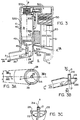
- the actuator mechanism 200 includes a compression spring 210, a helical torsion spring 220, a rotary (helical) cam 230, and a driver 240. Each of these elements is oriented in axial alignment with the longitudinal axis B of canister 30.
- the actuator release mechanism 300 includes a trigger mechanism and a motor 321 for driving the trigger mechanism, which are located off of axis B.
- Rotary cam 230 which is illustrated also in FIGS. 13A, has a first cam surface 232 which cooperates with a pair of cam followers 430.
- Cam followers 430 are attached to chassis 400 in durable body 2 on opposite sides of cam 230 in an appropriate location.
- Rotary cam 230 will thus rotate in one direction with cam surface 232 sliding against cam followers 430 so that rotary cam 230 moves upwardly along axis B shown in FIG. 6 as it rotates.
- Rotary cam 230 has no effective lower cam surface. This allows cam 230 to move downwardly along axis B without rotating.
- Vertical motion is imparted by release of compression spring 210.
- Rotary motion is imparted by release of torsion spring 220.
- cam 230 translates up and down corresponds to the distance valve stem 32 must be depressed relative to canister body 31 to release a metered dose of aerosol.
- the distance the valve stem must be depressed is on the order of 0.1 inch (2.5 mm).
- Cam 230 may be made of any suitable material, such as DELRIN AF.
- rotary cam 230 is illustrated in an unwrapped view illustrating the .333 inch (8.46 mm) pitch, a height of 0.227 inches (5.77 mm), a distance D1 of 0.1 inch (2.5 mm) plus the thickness of cam followers 430, and a helical face cam.
- Rotary cam 230 is secured at its top to compression spring 210 and to torsion spring 220, as shown in FIG. 6. The other ends of springs 210 and 220 are fixed, e.g., to chassis 400 or body 2.
- Rotary cam 230 is secured at its bottom to release ring 233, by a keyed interconnection including key protrusion 239 (shown in face view of FIG. 13A) of cam 230 and slot 235 of release ring 233. Cam 230 does not rotate relative to release ring 233.
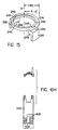
- release ring 233 is an annular ring, having a radial groove (or recess) 236, a radial slot 234, and a keyway 235 for securing release ring 233 to cam 230.
- Release ring 233 also may be surface treated to improve hardness, e.g., chrome plating. It is preferably a hardened tool steel ring (65-70 Rockwell C).
- the trigger mechanism includes a trigger pin 312 with a generally rectangular cross sectional base 311 and a multifaceted tip 313.
- trigger pin 312 has a first position where the top surface 343 of its tip 312 rests underneath release ring 233 in groove 236, with compression spring 210 in compression and torsion spring 220 in torsion.
- Compression spring 210 biases release ring 233 downwardly with groove 236 receiving trigger pin tip 313 securely seated inside.
- Torsion spring 220 biases release ring 233 to rotate, but trigger tip 313 being inside groove 236 and/or slot 234 prevents such rotation.
- Surface 342 is essentially parallel to the plane of release ring 233. Consequently, the downward pressure exerted by compression spring 210 acts on surface 343 to urge trigger pin 312 out from underneath release ring 233.
- trigger pin 312 is maintained in the first position, under release ring 233, by motor 321 (not shown in FIG. 6), in a manner that is described below.
- the trigger mechanism has a second position where trigger pin 312 is moved out from groove 236 and under release ring 233 and is located in slot 234. Slot 234 and groove 236 are in radial alignment, with slot 234 being located in the outer perimeter of release ring 233. This is illustrated in FIG. 14B. This movement allows slot 234 to move downwardly, straddling trigger pin 312, and as a result depresses canister 30. Torsion spring 220, however, biases release ring 233 so that slot 234 presses against a side wall 341 of trigger tip 313. Consequently, torsion spring 200 remains in torsion.
- Side wall 341 also is provided with an angle ⁇ 3 relative to base wall 311A (see FIG. 12B) which responds to the rotational pressure exerted by the opposing inner wall of slot 234 to urge trigger tip 313 out of slot 324.
- the result of this ejection, when it occurs, is that release ring 233 (and rotary cam 230) will rotate as torsion spring 220 releases.
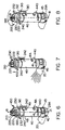
- motor 321 retains trigger pin 312 in its second position for a selected time period, so that cam 230 does not rotate (not shown in FIG. 7), as will be described below.
- Side wall 341 also is cut at an angle ⁇ 2 relative to the wall of base 311 opposite to wall 311A to correspond to release ring 233 to minimize or reduce energy lost from compression spring 210 due to friction, thereby to maximize the energy transfer from spring 210 to canister 30.
- the front end wall 311B may be cut at an angle suitable to provide clearance as tip 313 pivots, as described below.
- Slot 234 is configured with its walls cut at an angle ⁇ 1 relative to axis B as shown in FIG. 14B.
- trigger pin tip 313 top surface 343 is formed at an angle ⁇ 1 relative to a plane horizontal to axis B
- trigger tip side surface 341 is provided with an angle of ⁇ 3, relative to a plane parallel to axis B.
- the angles ⁇ 1, ⁇ 2, ⁇ 3 and ⁇ 1 are selected so that predetermined force magnitudes, which, if not counteracted by motor 321 holding trigger pin 312 in position, would cause trigger pin 312 to be forced out from under ring 233 to release compression spring 210 to deliver medication, and then out from slot 234 after the release of medication to release torsion spring 220 to recock compression spring 210.
- the angles are a matter of design choice, one suitable angle for each of ⁇ 1, ⁇ 2, ⁇ 3 and ⁇ 1 has been found to be about 15 degrees.
- Driver 240 has a base 241 having a top surface including a stepped drive dog 245, and a lower surface that includes two drive lugs 242 and two bottom surfaces 248, as illustrated in FIG. 15.
- Drive lugs 242 are respectively seated in notches 49 of cassette 4 (housing 40) and bottom surfaces 248 are in contact with base 34 of canister 30 (or disk 35, if one is used).
- the top of base 241 has a top planar surface 243 over a first portion and a second planar surface 244 over a second portion that is in a plane below top planar surface 243.
- step drive dogs 245 there are two step drive dogs 245 corresponding to the difference in height between surfaces 243 and 244 as illustrated in FIG. 15.
- One of the two steps 245 serves as a drive dog to rotate cam 230 acting on cam protrusion/step 239 whenever cassette 4 is rotated to the closed position.
- the other step 245 serves as a stop to prevent overrotating cassette 4 past the open position.
- the two steps thus limit cassette 4 to a rotation of about 180 degrees from open to closed positions.
- the position for insertion and withdrawal is at the full open position (180 degree position) relative to the closed position.
- Driver 240 is used for cocking rotary cam 230. This occurs by rotating cassette 4 about axis B to rotate driver 240. This causes one step drive dog 245 to engage and rotate cam 230. This in turn causes cam 230 and release ring 233 to rotate and place torsion spring 220 in torsion. Release ring 233 and cam 230 are then locked in place with torsion spring 220 in torsion, when they are rotated so that the top surface 343 of trigger pin 313 engages groove 236. (See FIGS. 8-10.)
- Driver 240 also is used for pressing canister body 31 downwardly, relative to valve stem 32 and cassette housing 40, to release an amount of aerosol.
- the release of compression spring 210 moves rotary cam 230 and driver 240 axially downward (without rotation) along axis B. See FIG. 7, where drive lugs 242 are illustrated as fully seated in housing slots 49.
- actuator release mechanism 300 comprising motor 321 and the trigger mechanism.
- motor 321 includes a lead screw 322 that rotates only in a single direction of rotation.
- lead screw 322 has multi-start threads, e.g., three or five starts.
- the trigger mechanism has a ratchet action comprising a ratchet member 323 whose movement is controlled by lead screw 322, a return spring 326, a main lever 314 and a secondary lever 315.
- Return spring 326 is used to return the ratchet member 323 to a starting position in the absence of an external force pressing ratchet member 323 against return spring 326.
- Ratchet member 323 is configured so as to catch on lead screw 322 so that an external force directed against return spring 326 causes ratchet member 323 to sit against a thread of lead screw 322. As a result, as long as the external force is applied, the position of ratchet element 323 can be controlled by rotating lead screw 322.
- the ratchet member 323 is a bent piece of spring steel about 0.002 inch (0.05 mm) thick having an upturned edge 324 that is secured to a pusher plate 328 by, e.g. a plastic rivet 329. Rivet 329 may have an aperture 330 for passing along lead screw 322.
- a guide bar 325 is provided extending between a motor mount 450 and a portion of chassis 400 and parallel to lead screw 322, over which return spring 326 is passed. Guide bar 325 provides stability, minimizes binding, and prevents plate 328 from rotating.
- plate 328 also has a bushing 328A having an aperture 331 which receives guide rod 325 and thus travels along lead screw 322 and guide 325, with return spring 326 between plate 328 and motor 321.
- motor 321 is secured to a motor mount 450 so that spring 326 is between plate 328 and motor mount 450.
- Trigger pin 312 is preferably mounted in a compound lever having a main lever 314, with trigger pin 312 protruding from one side of main lever 314, a secondary lever 315 that is pivotally connected to main lever 314 by rod 316, and a cut-out portion 317 in secondary lever 315.
- Main lever 314 is secured to chassis 400 so that it pivots about an axis 318 at its bottom end.
- Secondary lever 315 also is connected to chassis 400 about reaction pivot 319.
- Motor 321 may be, for example, part No. DNI2K51N1B, available from Canon, Inc.
- motor 321 consumes very little current, on the order of 130 ma when the motor is running, which occurs during a 2.5 second operation, of which the motor is off for a programmable time period, e.g., one second, which is typical for releasing a dose of medication and recocking actuator mechanism 200. This amount is surprisingly less than the energy consumed by a solenoid that is used to depress canister 30.
- Apertures 330 and 331 are preferably made in a low friction material, e.g., teflon, or an acetal resin such as DELRIN.
- Aperture 331 is configured for passing therethrough guide rod 325, such that return spring 326 is fixed between plate 328 and motor mount 450.
- Motor 321 and lead screw 322 are mounted in alignment with secondary lever 315 so that lead screw 322 passes through cut-out portion 317 of lever 315.
- Return spring 326 biases spring metal 323 outwardly, i.e., away from motor 321, and presses plate 328 against secondary lever 315.
- Lever 315 is in turn biased against plate 328 by the forces exerted on trigger pin 312 by springs 210 and 220. The latter forces, when they exist, are greater than the force of return spring 326.
- trigger pin 312 through levers 314 and 315, presses plate 328 toward motor 321 so that upturned end 324 is pressed against and captured in a thread of lead screw 322.
- Lead screw 322 preferably has 12 turns per inch and 3 start threads.
- the helix angle of lead screw 322 is configured to approach, but not exceed, the friction angle between edge 324 and screw 322. This ordinarily requires a relatively large pitch, e.g., 12 turns per inch on a .138 inch (3.5 mm) outer diameter lead screw 322. In as much as there is no control of the rotational position of lead screw 322 when it stops, the return of edge 324 would be imprecise. It was discovered that, to increase the accuracy of the latching position where edge 324 engages a thread of screw 322, a multistart thread, specifically a three start thread is employed.
- a three start thread has a distance of .027 inch between adjacent threads. This is because the three start thread is the superposition of three one start threads each offset equally, along the screw length. This provides for improved positioning resolution without either monitoring the rotational position of screw 322, rotating screw 322, or using additional position sensing contact switches. Use of a five start thread provides improved position control.
- Guide 325 and lead screw 322 provide for maintaining plate 328 and spring metal 323 properly oriented so that upturned edge 324 will again catch in one of the threads of lead screw 322 on the next advance event.
- motor 321 operates only in one direction of rotation and primarily operates only as a brake to restrain plate 328 and secondary lever 315 and trigger pin 313 from withdrawing.
- motor 321 efficiently controls movement of trigger pin 312 to release a dose of aerosol medication.
- the electrically operated motor does not provide the actuation force driving the motion of canister 30 to release the aerosol.
- Upturned edge 324 is preferably bent with a curved edge, rather than a straight bend, so that it bows and is easily captured by the vertical wall of the threads of lead screw 322.
- upturned end 324 will be urged into a thread of lead screw 322 by lever 315, and will be passed so that it rides up and over the angled flights of the thread in succession by return spring 326 (until trigger pin 312 is placed under release ring 233 and forced back by spring 210).
- the apparatus is in the ready-to-fire position with mouthpiece 20 already rotated by the user into the open position.
- Compression spring 210 is maintained in compression between chassis 400 and rotary cam 230.
- Torsion spring 220 is maintained in torsion between chassis 400 and rotary cam 230.
- Trigger pin 312 is positioned underneath release ring 233 and is seated in groove 236 with spring metal edge 324 engaged with lead screw 322 and return spring 326 in light compression.
- Driver 240 is positioned with bottom surfaces 248 flush against disk 35 which is flush against bottom 34 of canister 30, without depressing valve stem 32, and drive lugs 242 are partially inserted in notches 49.
- Protrusion 41A is positioned in annular recess 405 in the open position and locked in position by latch 39 so that cassette 4 will not fall out of chassis 400, receptacle 520, and body 2.
- the action of rotating cassette 4 to the open position places location mark 44 in a position that is sensed by contact switch 460 secured to chassis 400. This actuation is sensed by control electronics 50 and used to power up the electronics of device 6.
- a second microswitch (not shown) also is used to determine whether or not a cassette 4 is inserted in receptacle 520.
- control electronics 50 monitor the user's inspiratory flow, as described elsewhere, and determine when a provided delivery threshold is satisfied. When this occurs, motor 321 is actuated to rotate lead screw 322 to allow plate 328 to retract to a first stage position. This is shown in FIG. 7. The position may be controlled by rotating lead screw 322 a selected number of revolutions or preferably by using a contact switch 327 which is positioned to be contacted by plate 328 and shut off motor 321 in response to such contact. The latter is easier to implement.
- plate 328 moves away from canister 30 a first distance (as levers 314 and 315 pivot in response to the pressure exerted on trigger pin 312 by release ring 232).
- the first distance is selected so that tip 313 of trigger pin 312 slides out from groove 236 under release ring 233 and into ring slot 234.
- cam 230 is no longer supported by trigger pin 312 and is translated downwardly by releasing compression spring 210. Accordingly, drive surfaces 246 also are pressed downwardly and press canister body 31 relative to valve stem 32 to release a dose of aerosol medication.
- cam 230 is prevented from rotating under the force of torsion spring 220, which is still in torsion, because trigger pin 312 is held in slot 234. Torsion spring 220 does, however, exert a force to bias release ring 233 slot 234 against trigger pin 312 and maintain spring metal 323 edge 324 pressed against the vertical thread wall of lead screw 322.
- control electronics 50 starts a timer.
- the timer controls how long motor 321, and hence trigger pin 312, is maintained in the first stage position.
- the time period is selected to be long enough to be sure that the desired dose of aerosol is released from canister 30 in its selected form, namely, dry powder, liquid or gas aerosol through the nozzle 22.
- motor 321 is again advanced to allow plate 328 to react further under the force exerted by ring slot 234. This allows lever 314 and lever 315 to rotate further and trigger pin 312 to be urged out of slot 234 because of the opposing angled faces of trigger pin 312, side face 341 and slot 234. This is shown in FIG. 8.
- the further advance of the motor may be limited by another contact switch or by a set time period corresponding to a given number of rotations and, hence, distance of travel of member 324 along lead screw 322.
- torsion spring 220 releases (in this case it unwinds). Because torsion spring 220 produces more force than compression spring 210, release of torsion spring 220 causes rotary cam 230 to rotate. As rotary cam 230 rotates, its upper cam surface 232 runs against stationary cam followers 430 and raises cam 230 upwardly. As rotary cam 230 moves upwardly, it compresses compression spring 210. Rotation and upward movement of cam 230 also results in releasing valve stem 32 so that canister 30 is closed to the atmosphere.
- canister 30 is a metered dose canister
- this release action places canister 30 with its metered dose chamber in fluid communication with the reservoir of medication and carrier or aerosol precursor material and refills the metering chamber.
- the refilling occurs relatively shortly after the dose was delivered and, consequently, additional agitation of the medication and carrier or aerosol precursor prior to refill is not required.
- cam 230 comes to rest in its uppermost position, with cam followers 430 at one end of cam surface 232, torsion spring 220 released, compression spring 210 compressed, and metered dose canister 30 with a filled metering chamber and ready for delivering the next dose.
- the helical torsion spring 220 is used to recock compression spring 210, by transferring its energy thereto without requiring the user to perform any operation. It should be understood that a more complex spring could be used in place of compression spring 210 and torsion spring 220, so that release of trigger pin 312 will transfer the energy that had been stored by a prior rotating cocking event to be stored in the axial compression component, for later use in depressing canister 30 for releasing the next dose. It also should be understood that the direction of rotation about axis B for the various operations described herein maybe clockwise or counterclockwise, with appropriate mirror image parts and angles being usable.
- cam 230 continues to advance for a period of time, e.g., 0.5 to 2 seconds, or for a number of revolutions, that is sufficient for cam 230 to rotate upwardly on cam followers 430.
- the uppermost position of cam 230 is high enough so that when return spring 326 releases, it drives plate 328 along guide rod 325 back to the initial ready-to-fire position and returns trigger pin 312 to a pre-ready-to-fire position positioned underneath release ring 233.
- compression spring 210 is compressed, torsion spring 220 is released, and rotary cam 230 is held in its uppermost position by cam followers 430 over trigger pin 312.
- the pre-ready-to-fire condition is followed by a cocking operation, which places device 6 in the ready-to-fire condition.
- the cocking operation is performed by rotating cassette 4 into the closed position.
- one of the drive dogs 245 of driver 240 engages protrusion step 239 at the bottom of rotary cam 230 and causes cam 230 to rotate.
- This rotates cam 230 relative to cam followers 430.
- cam 230 will move downwardly on cam surface 232 as it rotates until it is supported by trigger pin 312 acting on the release ring 233.
- cam 230 will continue only to rotate until groove 236 of release ring 233 is again engaged with the top surface of trigger pin 312 and places cam followers 430 at the other end of cam surface 232.
- the engagement occurs at less than about 10° from the fully closed position (0°).
- torsion spring 220 will tend to release. This results in slot 234 acting on trigger tip 313, which also inhibits rotation. This locks torsion spring 220 in torsion.
- device 6 is ready to be opened for delivering aerosol medication.
- mouthpiece 20 has a length of about 1.38 inches (35 mm) from the center of rotation (Axis B), the patient has sufficient leverage to rotate cam 230 and place torsion spring 220 in torsion, with sufficient force to drive cam 230 to compress spring 210 after the next delivery of medication.
- compression spring 210 stores on the order of 8 pounds (3.629 kg) which is sufficient to depress valve stem 32 when spring 210 is released.
- Torsion spring 220 preferably stores on the order of .9 pounds-inches (1.0 kg-cm) which is sufficient to compress compression spring 210 after the release of a dose of medication.
- trigger pin 312 is used to engage slot 234 to prevent torsion spring 220 from releasing and to rest underneath release ring 233 to prevent compression spring 210 from releasing.
- the advantage of this structure is that the distance of travel of cam 230 along axis B for depressing canister 30 and for reinserting trigger 312 under release ring 233 is increased by the depth of groove 233, e.g., .015 inches.
- the angular configuration of trigger tip 313 may be modified if necessary, to provide the required clearance as well as the restraining and ejection functions.
- compression type release spring 326 with a helical torsion spring that is mounted about pivot 318 and to provide pusher plate 328 with a flange that hooks onto secondary lever 315 (not shown).
- the torsion spring is used to act on primary lever 314, which in turn will pull secondary lever and plate 328 towards canister 30 for resetting trigger pin 312 under release ring 233 when the forces pressing plate 328 towards motor 321 are removed.
- Yet another variation could use a torsion spring secured about secondary lever 315 pivot 316.
- Another advantage of the present invention is that it provides opening mouthpiece 20 as a passive event, whereby it requires little effort. It also obviates the need for the patient to have to cock the device immediately prior to use. This can be important to patients who are in distress or suffering a severe asthma attack and who might in panic forget or be unable to cock a device.
- the time that motor 321 is maintained in the first stage, with valve stem 32 depressed relative to canister body 31, can be selected and controlled by control electronics 50. Accordingly, the present invention is particularly useful with canisters, valve stem receptacle flow paths, and/or nozzles that have relatively slow or long release times, i.e., the time that the valve stem must be depressed to maintain open the metering chamber (for a metered dose inhaler) or a straight valve canister to release the proper dosage of aerosol medication.
- most available metered dose inhalers have a release time on the order of 90-100 msec, such that the valve stem must be held down for about one-tenth second to ensure complete release. This is easy for most individuals to achieve.
- Slow release valves may have a greater release time, e.g., on the order of one-quarter second, three-quarter seconds, two seconds, or more. The release time of this length is more difficult to achieve manually on a reliable basis.
- the present invention is able to deliver medications formulated to have long release times which heretofore could not be used in a metered dose inhaler because of the difficulty of providing the required release time.
- This feature also is particularly useful with straight valve canisters and dry powder delivery systems where the release time controls the amount of medication released.
- durable body 2 may be formed of a left half 11, a right half 12, and an airway cover 13, which provide a portable, hand held device.
- Body 2 also includes a display 510, preferably mounted in one of housings 11 and 12. Enclosed inside housings 11 and 12 are one or more batteries 60, actuator mechanism 200, actuator release mechanism 300, chassis 400, control electronics 50, a receptacle 520 for receiving cassettes, and flow transducer 600.
- Display 510 may be a liquid crystal display (LCD) device for displaying alphanumeric characters of measured flow or pulmonary function parameters, or instructions to the patient for using device 6 under microprocessor control.
- the LCD display may display quantitative or qualitative measures.
- One such LCD display 510 is a custom part model No. 0219-3211-F14 available from DCI, Olathe, Kansas. It provides for display, in response to software programming, of one or more of shot count of released (delivered) and/or remaining doses of medication, a low battery indication, a warning icon, e.g., "consult your doctor," three arrows to indicate inadequate, nominal or acceptable pulmonary function, annunciations for total exhaled volume, peak flow and annunciations indicating the day of week, time, month and year.
- a warning icon e.g., "consult your doctor”
- the display features of device 6 also may include a light emitting diode (LED) array 510' for indicating various parameters, for example, (1) that the device is on, (2) ranges of determined breath flows, e.g., good flow corresponding to successful delivery, bad flow corresponding to aborted delivery, (3) a qualitative measure of a measured pulmonary function, e.g., normal, nominal, and abnormal, and (4) relative changes in measured pulmonary function, e.g., improving the same degrading conditions.
- LED array 510' may include three LED devices, e.g., green, amber and red (or three of the same color), and appropriate labeling printed on housing 11 or 12.
- a selector switch also may be provided to indicate which parameter is being displayed on array 510'.
- Control electronics 50 preferably includes a microcontroller device including a microprocessor, RAM and ROM memory, and buffers, and also includes external analog-to-digital converters, latches, RAM/ROM memory, and signal conditioning circuits for receiving and transmitting signals in and out of control electronics 50, in digital and/or analog form.
- a microcontroller device including a microprocessor, RAM and ROM memory, and buffers, and also includes external analog-to-digital converters, latches, RAM/ROM memory, and signal conditioning circuits for receiving and transmitting signals in and out of control electronics 50, in digital and/or analog form.
- Such devices include a model 68HC11D3 microcontroller available from Motorola, analog to digital converter part No. AD7701 available from Analog Devices, and interface amplifier model No. AD22050 available from Analog Devices for conditioning the signal from the pressure transducer for digitization.
- the microcontroller, memory, and analog-to-digital converter must have sufficient capability and processing speed for processing the output signal produced by flow transducer 600, convert the output signal to the flow rate signal and, in accordance with selected protocols, derive a flow value signal from the sensed flow rate for causing actuator release mechanism 300 to release a dose of aerosol during inspiration of the patient and determine pulmonary functions based on the acquired flow signals.
- a suitable sampling rate is greater than 60 Hz, e.g., 75 Hz, for analog to digital conversion and processing.
- Chassis 400 is secured to one or both of housings 11 and 12 such that it is adjacent an interior receptacle 520 for receiving cassette 4.
- Mounted to chassis 400 are cam followers 430, keyplate 440 for receiving only cassette 4 having protrusions 41 that correspond to the plurality of slots cut in keyplate 440, motor mount 450 for mounting actuator release mechanism 300, annular recess 405 and contact switch 460 for sensing the presence of location mark 44 on cassette 4 indicating that cassette 4 is fully rotated to the open position.
- Chassis 400 is securely mounted to body 2.
- Receptacle 520 includes a first section that receives the upper part of housing 40 and a second section that receives the lower part 45 of housing 40.
- a ledge 447 separates the upper and lower receptacle sections and receives bearing surface 47 of cassette 4.
- Contact switch 462 is used to indicate that cassette 4 has been inserted in the receptacle adjacent to chassis 400.
- FIG. 16E one suitable form of the durable body 2, excluding airway cover 13, is shown.
- housing 11 is shown with receptacle 520 for receiving cassette 4 having annular recess 405 and keyplate 440 is shown.
- This embodiment includes two batteries 60 and LCD display 510 and LED array 510' within housings 11 and 12.
- body 2 is provided with a contour that is easy for the patient to hold securely.
- the larger side planar walls of housing 11 and 12 are each angled at an angle of about 4.5°. It should be understood that alternate configurations of housings 11 and 12 could be used.
- airway cover 13 connects to the bottom of body 2, more specifically, housings 11 and 12, after they have been secured together.
- Airway cover 13 includes ports 507 at the larger end distal to the patient's airway, and has a curved edge 501 in a horizontal plane at the proximal end, adapted to receive the perimeter of region 29A of top end opening 29 of mouthpiece 20. This allows mouthpiece 20 to rotate and maintain a close fit with the airway between airway cover 13 and the bottom of housings 11 and 12.
- airway cover 13 is provided with a comer surface bend indicated by 509, which receives the mouth end 25 of mouthpiece 20 when cassette 4 is rotated to the closed position.
- This provides a neat outer appearance and a relatively smooth surface for durable body 2, which makes its convenient to carry in a pocket or pocketbook. It also provides a convenient mechanism for blocking the open end 23 of the airway so that material is not lodged in the flow path. It also eliminates the need for a separate cap to cover the opening.
- the distance between the flat wall section designated 508 of airway cover 15 and the bottom of housings 11 and 12, designated as wall 506, is on the order of .38 inches (9.65 mm) and a width of .90 inch (22.86 mm) at the maximum dimensions.
- the side walls taper at nine degrees, 4-1/2° per side, to follow the outside of housing 11 and 12.
- flow transducer system 600 includes a pressure transducer 505, a durable flow measurement section having a contoured surface built into wall 506 at the bottom of housings 11 and 12, airway cover 13, and a pressure port 516.
- the contour of wall 506 is flat in the cross section end view as shown in FIG. 18C.
- Airway 601 mates with the airflow path 24 (through mouthpiece 20 end 23 and top end opening 29 the lower portion of 45 of housing 40, and out aperture 43).
- Airway 601 comprises the bottom wall 506, made of the mated housings 11 and 12, and airway cover 13.
- flow through path 601 is sensed at pressure tap 516 in wall 506 and at atmospheric pressure (not shown) by pressure transducer 505.
- the output signal of transducer 505 is converted to a digital value by control electronics 50 at a selected sampling rate and integrated at that sampling rate to obtain inhaled or exhaled volume. Drug dispensation timing and therapeutic decisions are based upon these measurements of flow rate and volume.
- Airway cover 13 is removable to facilitate cleaning of the durable flow measurement section. It has a rectilinear wall section 508 which defines a cross sectional area with opposing wall 506. Wall section 508 has a corner 509 which opens out at almost a 90° angle to provide a larger dimensioned chamber 550.
- the distal end of chamber 550 has apertures (ports) 507 for air flow therethrough without any significant pressure drop across apertures 507.
- the type of opening is not critical as long as chamber 550 allows the flow into the chamber to expand. Hence, a 90° bend is convenient, but not required.
- Wall 506 has at the proximal end a tapered lead-in section which includes a ramp indicated by reference 511.
- Ramp 511 reduces the cross-sectional area between walls 506 and 508 at the beginning of ramp 511 (indicated by reference 513) to a minimum cross sectional area at orifice throat 515.
- Wall 506 includes an undercut portion 512 under throat 515, which connects throat 515 to a wall segment 519, is in the same plane as wall 506 proximal to ramp 511 and provides about the same cross sectional area as at the beginning of the ramp 511.
- Walls 506 and 508 are thus constructed to form an asymmetrical structure that comprises elements of a pneumatic diode, a fixed orifice flow meter, and venturi port flow meter.
- a pneumatic diode is a structure that presents one flow resistance as the air passes in one direction across the surface and a different flow resistance as the air flow passes in the reverse direction.
- a fixed orifice meter is one that presents an orifice in the path that is generally symmetrical with the airflow path, but of smaller dimension. Flow through the orifice creates a differential pressure across the orifice which can be measured by sensing the pressure on either side of the orifice in a conventional manner. It is noted that the sides of airway cover 13 could be made straight, rather than tapered. If so, then the cross sectional area between throat 515 and wall 508 must be accordingly adjusted to provide the same orifice area as when the side walls are tapered.
- the orifice meter principle is simple. In order to generate a flow through an orifice there must be a pressure difference across the orifice. If there is no pressure difference then there will be no flow. Likewise, if there is a flow across an orifice, there will be a pressure differential that can be measured.
- the flow rate, Q is dependent on a string of constants, the square root of the inverse of the air density and the square root of the difference in pressure across the orifice.
- Q actual K A 2 ⁇ 2g c P 1 - P 2
- K and A are constants dependent on the system geometry and g c is a dimensional constant. In the present invention, only the pressure on the patient side of the orifice and the atmospheric pressure are measured.
- the flow rate vs pressure drop curve is parabolic. Therefore, it would require a huge dynamic signal range to detect the small pressures generated at near zero flows and also not peg the system signal during high flow rates.
- the low flow rate sensitivity in one direction is required to measure accurately inhale maneuvers, which typically range from 0-200 liters per minute.
- the large flow rate range in the other direction is required to measure the high flow rates during, e.g., a forced exhale maneuver which typically range from 0-800, more preferably 0-720, liters per minute. The latter are used to measure a pulmonary function.
- wall 506 behaves essentially like an orifice meter, except that there is a back eddy created by undercut 512.
- the back eddy helps increase the flow resistance in the inhale direction, thus adding to the total differential pressure.
- venturi effect is also parabolic with respect to flow rate.
- the relative position of pressure tap 516 on ramp 511 determines the magnitude of the venturi effect. This allows for varying the difference between the exhaled and inhaled sensed pressures ranges from between 2:5 and 1:100 or more, based on careful selection of the location of pressure tap 516 on ramp 511.
- the venturi effect can be made strong enough so that sensed pressure can go negative with respect to atmospheric pressure at exhaled flow rates by placing pressure tap 516 very near the orifice throat 515.
- wall 506 of the present invention yields a structure where sensed pressure resulting from a flow in one direction can be radically different from sensed pressure from the same magnitude flow in the other direction.
- the inhaled flow rate vs. pressure drop curve depends mostly on the selected size of the orifice, i.e., the distance between throat 515 and wall 508, and somewhat on the shape of undercut 512. It also depends on pressure tap 516 position on ramp 511. The exhale curve also depends on orifice size, but is radically changed by the position of pressure tap 516 along ramp 511 relative to the venturi throat 515. This allows for measuring flow rates in both directions using the full range of the transducer in each direction, even though the maximum flow rates have different magnitudes.
- the distance between throat 515 and wall 508 is 0.185 inches (4.69 mm).
- the dimensions of undercut 512 is a radius of 0.067 inches (1.7 mm) having a centerpoint that is about 0.745 inches (18.9 mm) from backwall 517.
- Backwall 517 is part of the durable body 2 and interconnects with the backwall of airway cover 13 that includes apertures 507.
- the thickness of wall 506 at the throat 515 is approximately .161 inches (4.24 mm).
- Ramp 511 is comprised of two cylindrical segments having opposite curvatures.
- the first curve begins tangential with wall 506 at end 513 has a radius of about .732 inches (18.6 mm) from a centerpoint spaced .6 inches (152.4 mm) from the orifice throat 515, perpendicular to wall 506 and wall 508.
- Pressure tap 516 is preferably a circular hole that extends through wall 506 and terminates in ramp 511 facing wall 508. Pressure tap 516 is preferably normal to the surface of wall 506 in which it terminates and spaced to one side or the other of the midplane as illustrated in FIG. 18C. The precise location of pressure tap 516 is a matter of design choice for the particular use of the device. Pressure tap 516 is connected to transducer 505 by a flexible plastic tube 520, e.g., PVC. The PVC tube need not have the same diameter as tap 516. The diameter should not be so small as to wick moisture, e.g., 1/32 to 1/16 of an inch inner diameter. The orifice of pressure tap 516 will be about .030 inches.
- the pressure versus flow rate curve along flow path 601 is typically non-linear in both directions. Applicants have realized that it is impractical to design and construct a flow path 601 with precise dimensions to obtain a flow having linear pressure vs flow rate characteristics.
- linear devices are too bulky for a handheld, portable device and typically contain screens or other orifice arrays which become clogged or plugged during use and need to be cleaned or replaced to avoid inaccurate measurements.
- a linear relation is not required and can be dispensed with by calibrating the flow path 601, as actually built, to produce from the actual sensed flow calibrated data.
- flow transducer system 600 as part of durable body 2
- applicants have realized that only flow path 601 needs to be calibrated, and not flow path 24. This further simplifies construction of mouthpiece 20 and cassette 4, and avoids the need to maintain tight tolerance controls for the construction of those other parts.
- the measurement made is not the pressure drop through the entire system flow paths 24 and 601, which might be changed slightly by minor variations in cassette 4. Rather, the pressure drop measurement is obtained only across the flow path 601 between housings 11 and 12 and airway cover 13, and hence is independent of minor variations in cassette 4. Further, total pressure drop through the entire system is also mostly independent of cassette 4 manufacture variations between the orifice 515 in the flow measurement section is substantially smaller and thus more restrictive than the port 23 and mouthpiece 20 in cassette 4.
- a calibration look-up table is derived and stored in nonvolatile memory of control electronics 50 for each body 2. This provides for measuring a flow dependent pressure signal, i.e., the voltage signal output from transducer 505 and looking up the corresponding calibrated flow value.
- the look-up table is a selected number of data points long, e.g., 59 points.
- the look-up table may be considered as two arrays or, tables, each having 28 data points for flow in each direction and sharing the zero flow rate.
- Control electronics 50 thus obtains the flow dependent signal, applies the obtained value to the look-up table, and performs piecewise linear interpolation between the points in real time so that it can measure rapidly changing flow rates.
- the calculated flow values are then integrated to determine volume or used to measure a pulmonary function, as the case may be.
- the look-up table is generated during the calibration of each device 6. Although in the preferred embodiment the valid flow values, i.e., values above a selected noise threshold, are always integrated, in an alternate embodiment, integration need not occur unless a flow volume is required.
- an automated calibration routine is used to determine the look-up table.
- the uncalibrated durable body 2 is placed on a fixture that terminates in a dummy disposable cassette 4, the same way that a patient's drug cassette 4 would be inserted into the device.
- a known air flow is introduced through the durable flow path 601 by a calibrated flow controller.
- the flow rate and transducer 505 response to a known flow are recorded by a computer (not shown). Further, the flow rate is adjusted to the next flow level by the flow controller, and the second and third steps 2 are repeated for, e.g., up to 59 different flow rates in the two flow directions.
- Fifth, the recorded data is transformed into a calibration table and may be run through a curve fitting routine to look for outlying or bad data points.
- a curve fitting routine may be used to find the best fit through the data prints to a desired degree of accuracy, e.g., 2nd order.
- a calibration table is then generated and downloaded into the RAM memory of control electronics 50.
- the table may be the raw data or curve fit data points.
- the calibration is then spot checked at several flow levels to assure proper loading of the table.
- a check sum is also stored in memory with the calibration table so that the look-up table can be checked for corruption each time the device 2 is turned on.
- a preferred flow sensing transducer 505 used to measure these pressure changes is a resistive strain-gauge type device having two ports. One port is vented to ambient pressure. The other port is connected by tube 520 to the pressure tap 516 which is located within airway 601, preferably on ramp 511 (see Fig. 18c). Pressure changes at the airway port 516 cause the resistances within sensor 505 to change. These resistance changes are provided in the form of a variable voltage output which is digitized by control electronics 50. The digital value is converted to a corresponding flow value using the predetermined calibration look-up table stored in the system memory PROM, ROM, or nonvolatile RAM.
- One suitable transducer 505 is model NPH-8-002.5DH, available from Lucas Novasensor, Fremont, California.
- Pressure sensors 505 of this type are known to suffer from several problems.
- the devices exhibit thermal and long-term drift, causing the output signal to wander slightly after power-up.
- the output signal also varies with the orientation of the sensor. Normally, these effects would be negligible.
- the parabolic nature of the flow-pressure curve makes the accuracy of look-up table conversion very sensitive to these offset changes. This is because, at low flow rates, a very small change in the pressure signal maps into a relatively large change in the calculated flow rate.
- the inventors discovered that the inherent noise of the unfiltered digitized signal during a zero-flow state is about ⁇ 2 A/D counts.
- the inventors discovered that even at low flow rates, when the sensitivity to flow variations is low, maintaining an airway flow rate which produces a pressure signal constant to within ⁇ 2 A/D counts for any length of time is virtually impossible. Therefore, they realized, a pressure signal remaining constant for a relatively long period of time is indicative of a zero-flow state. This criterion was accordingly selected and used to determine appropriate times to measure and modify the zero-flow offset value.
- the method assumes that any drift occurs slowly enough not to influence the peak-to-peak variance calculated over the specified time period, and that orientation changes are transient events.
- the device maintains a buffer holding the last 25 A/D values, which corresponds to 1/3 of a second of pressure data.
- the A/D values are the digitized output of pressure sensor 505. After a new data point is placed in this buffer, the difference between the minimum and maximum values in the buffer is calculated. If the calculated difference is less than or equal to three, then the system concludes that a zero-flow condition exists, and a new offset is calculated.
- the mean value of the 25 values stored in the buffer is first calculated.
- the difference between this calculated average, representing the current zero-flow reading, and the base value for this zero-flow signal is calculated. This difference is then stored as a new A/D offset term. If each direction of flow is to have a symmetrical range of A/D counts, then, the base zero flow condition is the midpoint of the A/D range, e.g., zero for a bipolar A/D converter, or 32768 for a 16-bit unipolar A/D converter.
- the offset drift correction aspect of the present invention will be better understood by the following example.
- the system measures an average zero-flow pressure signal of 30000 A/D counts.
- the range of the unipolar A/D converter is 0-65535 counts, corresponding to an input range of 2.5 volts, such that each A/D count is 38 ⁇ V.
- the offset term is subtracted from all subsequent A/D measurements before these readings are mapped into flow values using the look-up table.
- Fig. 20 is a representative plot showing in the lower curve the actual offset drift of the flow sensor over time (in number of data points, where the time interval between data points is 13.3 ms) and in the upper curve the corrected value according to the offset correction routing of the present invention. It is noted that many other combinations of filter length and peak to peak difference may work equally well. Non symmetrical ranges of A/D counts also could be used if it is desired to have either greater resolution or a greater flow range in one of the two directions. This approach also could be performed using hardware circuits as well as software controlled microprocessor signal processing.
- FIG. 19A a block diagram illustrating the interaction of control electronics 50, actuator release mechanism 300, actuator mechanism 200, and position sensor 460, e.g., a contact switch, are shown.
- a flow diagram showing the essentials of a process for controlling the release of a dose of aerosol medication is shown in Fig. 19B.
- One suitable routine is as follows. When mouthpiece 20 is rotated into the open position, position sensor 460 senses location mark 44 and initializes the control electronics at step 801. Step 801 is followed by processing flow data, including digitizing the output signal provided by transducer 505, passing the digitized data into a buffer storage memory, mapping the acquired pressure data using the look-up table into determined flow rates, and determining current calibrated flow rate information at step 802.
- the system determines whether or not the time for releasing a dose has occurred.
- the flow rate is checked to determine if it is an inhalation. If it is, the acquired flow data is compared to preselected delivery threshold parameters. For example, as previously described in detail, the flow rate is checked first to determine if it is within a flow rate range. If it is, then the flow volume information is checked to see if it is in a flow volume range. If both ranges and satisfied simultaneously, then, at step 804, motor 321 is turned on, a "firing" flag is set, a "motor1" flag is set, and a two second alarm is set.
- step 802 the routine queries whether the "firing" flag is set at step 805. If the "firing" flag is not set, the routine returns to process additional new data at step 802. If the "firing" flag was set, then the routine checks to see if the "motor1" flag also is set at step 806. If the motor1 flag is set, then the routine queries at step 807 whether a fire active position sensor (contact switch 327) is actuated, which indicates that trigger pin 312 has moved enough to release compression spring 210 and a dose of medication.
- a fire active position sensor contact switch 327)
- step 808 the two second alarm is checked. If the alarm has not expired, the routine passes to step 802 for new data. If the alarm has expired, then at step 809 the motor 321 is turned off, and the "firing" flag is cleared. The two second alarm is used to preserve battery life. An error may be reported. Optionally, the error message is displayed on display 15. The routine then passes back to processing data step 802.
- step 810 the routine passes to step 810 where the motor is turned off, a "motor2" flag is set, the "motor1" flag is cleared, and a * second alarm is set, wherein * is the programmed delay interval.
- the motor is then turned off for the programmed delay interval.
- the interval is selected to provide for complete release of the dose of medication.
- this time depends upon the nozzle dimensions and may be any number of milliseconds, e.g., from less than 1/10 of a second to more than 2 seconds.
- this provides for delivery of medication formulations, using a timed (slow) release valve, that are not presently obtainable with conventional meter dose devices.
- use of timed-release valves and small diameter nozzles may improve the delivery of inhaled steroid formulations, i.e., reducing the amount of drug deposited into the mouth.
- the routine returns to process new data at step 802. If at step 806 the "firing" flag is set and the "motor1" flag is not set, then the routine waits for the dose to be delivered and passes to step 811 where the "motor2" flag is checked. If the "motor2" flag is set, then the routine checks to see if the programmed delay * interval has expired at step 812. If it has not, the routine returns to process new data at step 802. If it has, then the routine passes to step 813 where the motor is turned on, the "motor3" flag is set, the "motor2" flag is cleared and a 0.5 second alarm is set, and thereafter the routine passes to process the new data at step 802.
- step 811 the routine checks to see if the 0.5 second alarm has elapsed at step 814. If it has not, then the routine returns to step 802 for new data. If it has, then at step 815 the routine turns off the motor, clears the firing flag, clears the "motor3" flag, adjusts the shot counter (decreasing the number of remaining dosages for and/or increasing the number of doses delivered by, the given cassette 4), stores the record (e.g., peak flow rate and total inhaled volume or the flow rate and flow volume at drug delivery), and returns to obtain new data at step 802.
- the routine turns off the motor, clears the firing flag, clears the "motor3" flag, adjusts the shot counter (decreasing the number of remaining dosages for and/or increasing the number of doses delivered by, the given cassette 4), stores the record (e.g., peak flow rate and total inhaled volume or the flow rate and flow volume at drug delivery), and returns to obtain new data at step 802.
- the selected time interval for example, 1/2 second, provides sufficient time for trigger tip 313 to pass out of slot 234 and the release of torsion spring 220, to reload compression spring 210, and to refill the metered dose chamber of canister 31 following release of the medication.
- device 6 is turned off by rotating mouthpiece 20 so that contact switch 460 no longer engages location mark 44.
- the press, controlled hold, and release behavior of the present invention provides for the internal metering chamber of metered dose canister 30 to be refilled shortly after releasing the dose of medication. This is important because the metering chamber must be refilled, i.e., the canister released, after the canister is agitated. Typically, the patient is instructed to agitate the medication prior to release of a dose, but that agitation is for filling the chamber for the next dose.
- the precisely timed press and release behavior also ensures reproducible canister actuation. It also permits the use of canister nozzle combinations with a variety of emptying times because the emptying time parameter, i.e., the hold actuation time, is selectable and programmable. It should be understood that persons of ordinary skill in the art could develop considerably more complicated processes for sensing flow analyzing information and determining when to depress the canister to release a dose of aerosol medication. Such modifications are believed to be within the ability of a person of ordinary skill in the art.
Landscapes
- Health & Medical Sciences (AREA)
- Engineering & Computer Science (AREA)
- Life Sciences & Earth Sciences (AREA)
- Public Health (AREA)
- Physics & Mathematics (AREA)
- Pulmonology (AREA)
- Anesthesiology (AREA)
- Biomedical Technology (AREA)
- Heart & Thoracic Surgery (AREA)
- Hematology (AREA)
- Animal Behavior & Ethology (AREA)
- General Health & Medical Sciences (AREA)
- General Physics & Mathematics (AREA)
- Veterinary Medicine (AREA)
- Fluid Mechanics (AREA)
- Chemical & Material Sciences (AREA)
- Chemical Kinetics & Catalysis (AREA)
- Bioinformatics & Cheminformatics (AREA)
- Emergency Medicine (AREA)
- Biophysics (AREA)
- Infusion, Injection, And Reservoir Apparatuses (AREA)
- Measurement Of The Respiration, Hearing Ability, Form, And Blood Characteristics Of Living Organisms (AREA)
- Measuring Volume Flow (AREA)
- Nozzles (AREA)
Claims (10)
- Procédé pour corriger le décalage de dérive d'un transducteur ayant un signal de sortie analogique correspondant à la pression détectée d'un écoulement dans un sens quelconque dans un trajet d'écoulement, comprenant les opérations consistant à :(a) prévoir un convertisseur analogique-numérique ayant une gamme définie de comptes numériques et identifier une valeur de compte numérique de base de la gamme numérique correspondant à l'écoulement nul de base dans un sens quelconque;(b) convertir le signal de sortie du transducteur en une valeur numérique à un taux d'échantillonnage donné;(c) identifier une condition d'écoulement nul dans le trajet d'écoulement lorsque le signal de tension converti du transducteur ne varie pas plus d'un nombre choisi de comptes numériques sur une première période de temps;(d) déterminer une valeur de décalage de compte basée sur la différence entre la valeur de compte numérique de base identifiée et la sortie de compte numérique du convertisseur analogique-numérique pendant une condition d'écoulement nul identifiée; et(e) ajuster la sortie du convertisseur analogique-numérique suite à la condition d'écoulement nul identifiée de la valeur de décalage déterminée.
- Procédé selon la revendication 1, dans lequel l'étape (c) comprend en outre les opérations consistant à :maintenir un circuit tampon contenant un nombre choisi de valeurs numériques acquises en dernier;ajouter au circuit tampon chaque valeur numérique convertie à partir d'un signal de tension échantillonné et soustraire du circuit tampon la valeur numérique la plus ancienne pour chaque nouvelle valeur ajoutée;déterminer la différence entre les valeurs maximum et minimum dans le circuit tampon; etdéterminer qu'une condition d'écoulement nul existe quand la différence déterminée est inférieure à un second nombre choisi de comptes numériques.
- Procédé selon la revendication 2, dans lequel le second nombre choisi de comptes numériques est de l'ordre de quatre.
- Procédé selon la revendication 2 ou 3, dans lequel l'étape(a) comprend en outre le fait de prévoir un convertisseur analogique-numérique avec une gamme de comptes numériques de l'ordre de 65 536 comptes, et l'étape (c) comprend en outre le fait de choisir le nombre de valeurs numériques dans le circuit tampon comme étant de l'ordre de 25 valeurs et de déterminer qu'une condition d'écoulement nul existe quand la différence déterminée est inférieure à quatre comptes numériques.
- Procédé selon l'une quelconque des revendication 2 à 4, dans lequel l'étape (d) comprend en outre les opérations consistant à :déterminer la valeur moyenne du nombre choisi de valeurs numériques dans le circuit tampon; etdéterminer la valeur de décalage comme valant la différence entre le compte numérique de base identifié et la valeur moyenne déterminée.
- Appareil pour corriger le décalage de dérive d'un transducteur ayant un signal de sortie analogique correspondant à la pression détectée d'un écoulement dans un sens quelconque dans un trajet d'écoulement, comprenant :un convertisseur analogique-numérique ayant une gamme définie de comptes numériques et une valeur numérique dans la gamme numérique correspondant à l'écoulement nul de base dans un sens quelconque;un moyen pour commander le convertisseur analogique-numérique pour convertir le signal de sortie du transducteur en une valeur numérique à un taux d'échantillonnage donné;un moyen pour identifier une condition d'écoulement nul dans le trajet d'écoulement lorsque les valeurs numériques ne varient pas plus d'un nombre choisi de comptes numériques sur une première période de temps;un premier moyen pour déterminer une valeur de décalage basée sur la différence entre le compte numérique de base identifié et la sortie de valeur numérique du convertisseur analogique-numérique pendant une condition d'écoulement nul; etun moyen pour ajuster la sortie du convertisseur analogique-numérique de la valeur de décalage déterminée.
- Dispositif portatif autonome pour corriger le décalage de dérive d'un transducteur ayant un signal de sortie analogique correspondant à la pression détectée d'un écoulement dans un sens quelconque dans un trajet d'écoulement, comprenant :(a) un moyen fournissant un convertisseur analogique-numérique ayant une gamme définie de comptes numériques et identifiant une valeur de compte numérique de base de la gamme numérique correspondant à l'écoulement nul de base dans un sens quelconque;(b) un moyen pour convertir le signal de sortie du transducteur en une valeur numérique à un taux d'échantillonnage donné;(c) un moyen pour identifier une condition d'écoulement nul dans le trajet d'écoulement lorsque le signal de tension converti du transducteur ne varie pas plus d'un nombre choisi de comptes numériques sur une première période de temps;(d) un moyen pour déterminer une valeur de décalage de compte basée sur la différence entre la valeur de compte numérique de base identifiée et la sortie de compte numérique du convertisseur analogique-numérique pendant une condition d'écoulement nul identifiée; et(e) un moyen pour ajuster la sortie du convertisseur analogique-numérique suite à la condition d'écoulement nul identifiée de la valeur de décalage déterminée.
- Dispositif selon la revendication 7, comprenant en outre :(f) un moyen pour maintenir un circuit tampon contenant un nombre choisi de valeurs numériques acquises en dernier;(g) un moyen pour ajouter au circuit tampon chaque valeur numérique convertie à partir d'un signal de tension échantillonné et soustraire du circuit tampon la valeur numérique la plus ancienne pour chaque nouvelle valeur ajoutée;(h) un moyen pour déterminer la différence entre les valeurs maximum et minimum dans le circuit tampon; et(i) un moyen pour déterminer qu'une condition d'écoulement nul existe quand la différence déterminée est inférieure à un second nombre choisi de comptes numériques.
- Dispositif selon la revendication 7 ou 8, dans lequel le moyen (a) fournit un convertisseur analogique-numérique avec une gamme de comptes numériques de l'ordre de 65 536 comptes, et le moyen (c) choisit un nombre de valeurs numériques dans le circuit tampon de l'ordre de 25 valeurs et détermine qu'une condition d'écoulement nul existe quand la différence déterminée est inférieure à quatre comptes numériques.
- Dispositif selon la revendication 7, comprenant en outre :un moyen pour déterminer la valeur moyenne du nombre choisi de valeurs numériques dans le circuit tampon; etun moyen pour déterminer la valeur de décalage comme valant la différence entre le compte numérique de base identifié et la valeur moyenne déterminée.
Applications Claiming Priority (7)
| Application Number | Priority Date | Filing Date | Title |
|---|---|---|---|
| US07/664,758 US5404871A (en) | 1991-03-05 | 1991-03-05 | Delivery of aerosol medications for inspiration |
| US1124593A | 1993-01-29 | 1993-01-29 | |
| US10783 | 1993-01-29 | ||
| US08/002,507 US5394866A (en) | 1991-03-05 | 1993-01-29 | Automatic aerosol medication delivery system and methods |
| US08/010,783 US5450336A (en) | 1991-03-05 | 1993-01-29 | Method for correcting the drift offset of a transducer |
| US08/011,351 US5392768A (en) | 1991-03-05 | 1993-01-29 | Method and apparatus for releasing a controlled amount of aerosol medication over a selectable time interval |
| PCT/US1994/001082 WO1994017370A2 (fr) | 1991-03-05 | 1994-01-31 | Procede et dispositif pour corriger la derive du decalage d'un capteur de pression d'un debitmetre |
Publications (2)
| Publication Number | Publication Date |
|---|---|
| EP0683890A1 EP0683890A1 (fr) | 1995-11-29 |
| EP0683890B1 true EP0683890B1 (fr) | 2002-04-03 |
Family
ID=37478871
Family Applications (1)
| Application Number | Title | Priority Date | Filing Date |
|---|---|---|---|
| EP94907924A Expired - Lifetime EP0683890B1 (fr) | 1991-03-05 | 1994-01-31 | Procede et dispositif pour corriger la derive du decalage d'un capteur de pression d'un debitmetre |
Country Status (7)
| Country | Link |
|---|---|
| US (5) | US5522378A (fr) |
| EP (1) | EP0683890B1 (fr) |
| JP (1) | JP3532204B2 (fr) |
| AU (3) | AU6130594A (fr) |
| DE (1) | DE69430303T2 (fr) |
| ES (1) | ES2179068T3 (fr) |
| WO (4) | WO1994017370A2 (fr) |
Families Citing this family (381)
| Publication number | Priority date | Publication date | Assignee | Title |
|---|---|---|---|---|
| US5450336A (en) * | 1991-03-05 | 1995-09-12 | Aradigm Corporation | Method for correcting the drift offset of a transducer |
| US5404871A (en) * | 1991-03-05 | 1995-04-11 | Aradigm | Delivery of aerosol medications for inspiration |
| US5507277A (en) | 1993-01-29 | 1996-04-16 | Aradigm Corporation | Lockout device for controlled release of drug from patient-activateddispenser |
| FR2701399B1 (fr) * | 1993-02-16 | 1995-03-31 | Valois | Dispositif portatif de pulvérisation à actionnement déclenché par l'inhalation. |
| CH686872A5 (de) * | 1993-08-09 | 1996-07-31 | Disetronic Ag | Medizinisches Inhalationsgeraet. |
| US6675797B1 (en) | 1993-11-05 | 2004-01-13 | Resmed Limited | Determination of patency of the airway |
| US6390088B1 (en) * | 1993-12-13 | 2002-05-21 | Boehringer Ingelheim Kg | Aerosol inhaler |
| WO1996028205A1 (fr) * | 1995-03-14 | 1996-09-19 | Siemens Aktiengesellschaft | Atomiseur a ultrasons pourvu d'une unite amovible de dosage precis |
| CA2215331C (fr) * | 1995-03-14 | 2002-01-22 | Siemens Aktiengesellschaft | Atomiseur a ultrasons pourvu d'une unite de dosage precis amovible |
| US5758637A (en) | 1995-08-31 | 1998-06-02 | Aerogen, Inc. | Liquid dispensing apparatus and methods |
| US5809997A (en) * | 1995-05-18 | 1998-09-22 | Medtrac Technologies, Inc. | Electronic medication chronolog device |
| US6357442B1 (en) | 1995-06-08 | 2002-03-19 | Innovative Devices, Llc | Inhalation actuated device for use with metered dose inhalers (MDIS) |
| US6672304B1 (en) | 1995-06-08 | 2004-01-06 | Innovative Devices, Llc | Inhalation actuated device for use with metered dose inhalers (MDIs) |
| US20040237961A1 (en) * | 1995-06-08 | 2004-12-02 | Snow John Medlin | Inhalation actuated device for use with metered dose inhalers (MDIs) |
| SE504458C2 (sv) * | 1995-06-21 | 1997-02-17 | Lars Gunnar Nilsson | Inhalator för elektrisk dosering av substanser |
| US5724986A (en) * | 1995-11-06 | 1998-03-10 | Jones Medical Instrument Co. | Casing and spirometer for metered dose inhaler |
| AU7726096A (en) * | 1995-11-15 | 1997-06-05 | Regents Of The University Of Minnesota | System for detecting target respiratory flow rates |
| US5823179A (en) * | 1996-02-13 | 1998-10-20 | 1263152 Ontario Inc. | Nebulizer apparatus and method |
| US5676129A (en) * | 1996-03-14 | 1997-10-14 | Oneida Research Services, Inc. | Dosage counter for metered dose inhaler (MDI) systems using a miniature pressure sensor |
| AUPO126596A0 (en) | 1996-07-26 | 1996-08-22 | Resmed Limited | A nasal mask and mask cushion therefor |
| AUPO247496A0 (en) | 1996-09-23 | 1996-10-17 | Resmed Limited | Assisted ventilation to match patient respiratory need |
| AUPO301796A0 (en) | 1996-10-16 | 1996-11-07 | Resmed Limited | A vent valve apparatus |
| AUPO418696A0 (en) | 1996-12-12 | 1997-01-16 | Resmed Limited | A substance delivery apparatus |
| AUPQ104099A0 (en) | 1999-06-18 | 1999-07-08 | Resmed Limited | Forehead support for facial mask |
| US6561191B1 (en) | 1997-02-10 | 2003-05-13 | Resmed Limited | Mask and a vent assembly therefor |
| US6024089A (en) | 1997-03-14 | 2000-02-15 | Nelcor Puritan Bennett Incorporated | System and method for setting and displaying ventilator alarms |
| US6006747A (en) * | 1997-03-20 | 1999-12-28 | Dura Pharmaceuticals, Inc. | Dry powder inhaler |
| TW533865U (en) * | 1997-06-10 | 2003-05-21 | Glaxo Group Ltd | Dispenser for dispensing medicament and actuation indicating device |
| EP1647297B1 (fr) * | 1997-06-17 | 2016-05-11 | Fisher & Paykel Healthcare Limited | Système d'humidification pour un respirateur |
| US6044841A (en) | 1997-08-29 | 2000-04-04 | 1263152 Ontario Inc. | Breath actuated nebulizer with valve assembly having a relief piston |
| BR7702049U (pt) * | 1997-09-05 | 1999-09-14 | Chiesi Farma Spa | Bico pulverizador para utilização em inalador oral para medicamentos aerossóis |
| US6309623B1 (en) | 1997-09-29 | 2001-10-30 | Inhale Therapeutic Systems, Inc. | Stabilized preparations for use in metered dose inhalers |
| US6946117B1 (en) * | 1997-09-29 | 2005-09-20 | Nektar Therapeutics | Stabilized preparations for use in nebulizers |
| US6565885B1 (en) | 1997-09-29 | 2003-05-20 | Inhale Therapeutic Systems, Inc. | Methods of spray drying pharmaceutical compositions |
| US20020017295A1 (en) * | 2000-07-07 | 2002-02-14 | Weers Jeffry G. | Phospholipid-based powders for inhalation |
| US6433040B1 (en) * | 1997-09-29 | 2002-08-13 | Inhale Therapeutic Systems, Inc. | Stabilized bioactive preparations and methods of use |
| US20060165606A1 (en) | 1997-09-29 | 2006-07-27 | Nektar Therapeutics | Pulmonary delivery particles comprising water insoluble or crystalline active agents |
| US5954047A (en) * | 1997-10-17 | 1999-09-21 | Systemic Pulmonary Development, Ltd. | Methods and apparatus for delivering aerosolized medication |
| US7743765B2 (en) * | 1997-11-14 | 2010-06-29 | Astrazeneca Ab | Inhalation device |
| SE9704185D0 (sv) * | 1997-11-14 | 1997-11-14 | Astra Pharma Prod | Inhalation device |
| US7967011B2 (en) * | 1997-11-14 | 2011-06-28 | Astrazeneca Ab | Inhalation device |
| US20060213505A1 (en) * | 1997-11-14 | 2006-09-28 | Astrazeneca Ab | Inhalation device |
| US6116238A (en) * | 1997-12-02 | 2000-09-12 | Dura Pharmaceuticals, Inc. | Dry powder inhaler |
| US6142339A (en) | 1998-01-16 | 2000-11-07 | 1263152 Ontario Inc. | Aerosol dispensing device |
| DE69918267T2 (de) | 1998-01-16 | 2005-07-28 | 1263152 Ontario Inc., London | Anzeigevorrichtung zur verwendung mit einer abgabevorrichtung |
| US6119693A (en) | 1998-01-16 | 2000-09-19 | Resmed Limited | Forehead support for facial mask |
| US6039212A (en) * | 1998-02-20 | 2000-03-21 | Ccl Industries Inc. | Aerosol dispenser |
| US6336453B1 (en) | 1999-04-30 | 2002-01-08 | Trudell Medical International | Indicating device for aerosol container |
| US6729330B2 (en) | 1998-05-05 | 2004-05-04 | Trudell Medical International | Indicating device for aerosol container |
| US6082358A (en) | 1998-05-05 | 2000-07-04 | 1263152 Ontario Inc. | Indicating device for aerosol container |
| US6260549B1 (en) | 1998-06-18 | 2001-07-17 | Clavius Devices, Inc. | Breath-activated metered-dose inhaler |
| SE9802398D0 (sv) * | 1998-07-03 | 1998-07-03 | Astra Pharma Prod | Inhalation device |
| CN1320057A (zh) * | 1998-09-24 | 2001-10-31 | 阿斯特拉曾尼卡有限公司 | 吸入器 |
| US6234167B1 (en) * | 1998-10-14 | 2001-05-22 | Chrysalis Technologies, Incorporated | Aerosol generator and methods of making and using an aerosol generator |
| GB9825118D0 (en) * | 1998-11-16 | 1999-01-13 | Minnesota Mining & Mfg | Breath-actuated aerosol dispensers |
| US6088933A (en) * | 1999-01-26 | 2000-07-18 | Mallalieu; David H. | Drive rod and clutch disk for a paint brush and roller drying tool |
| EP1537887A1 (fr) * | 1999-03-06 | 2005-06-08 | Glaxo Group Limited | Systeme d'administration de medicaments |
| EP1169244B1 (fr) | 1999-03-12 | 2005-11-02 | Glaxo Group Limited | Vanne doseuse |
| US6223744B1 (en) | 1999-03-16 | 2001-05-01 | Multi-Vet Ltd. | Wearable aerosol delivery apparatus |
| US6202642B1 (en) | 1999-04-23 | 2001-03-20 | Medtrac Technologies, Inc. | Electronic monitoring medication apparatus and method |
| DE60022494T2 (de) | 1999-05-21 | 2006-01-26 | Mallinckrodt, Inc. | Vorrichtung zur resuspension von kontrastmitteln |
| JP4540906B2 (ja) * | 1999-06-05 | 2010-09-08 | イノバータ・バイオメッド・リミテッド | 放出システム |
| US6624885B1 (en) | 1999-06-10 | 2003-09-23 | Aradigm Corporation | Method and device for non-destructive analysis of perforation in a material |
| US7301621B2 (en) * | 1999-06-10 | 2007-11-27 | Aradigm Corporation | Method and device for non-destructive analysis of perforations in a material |
| US7148960B2 (en) * | 1999-06-10 | 2006-12-12 | Aradigm Corporation | Method and device for non-destructive analysis of perforations in a material |
| US9006175B2 (en) | 1999-06-29 | 2015-04-14 | Mannkind Corporation | Potentiation of glucose elimination |
| US7305986B1 (en) | 1999-07-23 | 2007-12-11 | Mannkind Corporation | Unit dose capsules for use in a dry powder inhaler |
| US7464706B2 (en) | 1999-07-23 | 2008-12-16 | Mannkind Corporation | Unit dose cartridge and dry powder inhaler |
| GB9920839D0 (en) | 1999-09-04 | 1999-11-10 | Innovata Biomed Ltd | Inhaler |
| US6235177B1 (en) | 1999-09-09 | 2001-05-22 | Aerogen, Inc. | Method for the construction of an aperture plate for dispensing liquid droplets |
| WO2001041846A1 (fr) * | 1999-12-11 | 2001-06-14 | Glaxo Group Limited | Distributeur de medicaments |
| AR026914A1 (es) * | 1999-12-11 | 2003-03-05 | Glaxo Group Ltd | Distribuidor de medicamento |
| GB9930374D0 (en) * | 1999-12-22 | 2000-02-16 | 3M Innovative Properties Co | Refillable device with counting means |
| CA2635489A1 (fr) | 2000-02-11 | 2001-08-16 | Respironics Respiratory Drug Delivery (Uk) Ltd | Appareil d'administration de medicaments |
| GB0003197D0 (en) * | 2000-02-11 | 2000-04-05 | Aid Medic Ltd | Improvements in and relating to controlling drug delivery |
| GB0003839D0 (en) * | 2000-02-19 | 2000-04-05 | Glaxo Group Ltd | Housing for an inhaler |
| GB0004456D0 (en) * | 2000-02-26 | 2000-04-19 | Glaxo Group Ltd | Medicament dispenser |
| CN100341483C (zh) | 2000-02-28 | 2007-10-10 | 维克丘拉有限公司 | 口服药物输递中或涉及口服药物输递的改进 |
| GB2360218A (en) * | 2000-03-18 | 2001-09-19 | Astrazeneca Uk Ltd | Inhaler |
| AU4867001A (en) | 2000-04-11 | 2001-10-23 | Trudell Medical International | Aerosol delivery apparatus with positive expiratory pressure capacity |
| US8336545B2 (en) | 2000-05-05 | 2012-12-25 | Novartis Pharma Ag | Methods and systems for operating an aerosol generator |
| US7971588B2 (en) | 2000-05-05 | 2011-07-05 | Novartis Ag | Methods and systems for operating an aerosol generator |
| US8404217B2 (en) | 2000-05-10 | 2013-03-26 | Novartis Ag | Formulation for pulmonary administration of antifungal agents, and associated methods of manufacture and use |
| US7871598B1 (en) | 2000-05-10 | 2011-01-18 | Novartis Ag | Stable metal ion-lipid powdered pharmaceutical compositions for drug delivery and methods of use |
| DK1280520T4 (en) * | 2000-05-10 | 2018-06-25 | Novartis Ag | Phospholipid based powders for drug delivery |
| GB0012465D0 (en) * | 2000-05-24 | 2000-07-12 | Glaxo Group Ltd | Monitoring method |
| US20020000225A1 (en) * | 2000-06-02 | 2002-01-03 | Carlos Schuler | Lockout mechanism for aerosol drug delivery devices |
| GB0013619D0 (en) * | 2000-06-06 | 2000-07-26 | Glaxo Group Ltd | Sample container |
| US6543443B1 (en) * | 2000-07-12 | 2003-04-08 | Aerogen, Inc. | Methods and devices for nebulizing fluids |
| CN1443081A (zh) * | 2000-07-15 | 2003-09-17 | 葛兰素集团有限公司 | 药剂配送器 |
| AU2001278131A1 (en) * | 2000-08-01 | 2002-02-13 | Shofner Engineering Associates, Inc. | Generation, delivery, measurement and control of aerosol boli for diagnostics and treatments of the respiratory/pulmonary tract of a patient |
| US20050066968A1 (en) * | 2000-08-01 | 2005-03-31 | Shofner Frederick M. | Generation, delivery, measurement and control of aerosol boli for diagnostics and treatments of the respiratory/pulmonary tract of a patient |
| IT1318765B1 (it) * | 2000-08-11 | 2003-09-10 | Med 2000 Srl | Ampolla nebulizzatrice per aerosolterapia |
| US6814073B2 (en) | 2000-08-29 | 2004-11-09 | Resmed Limited | Respiratory apparatus with improved flow-flattening detection |
| GB0021024D0 (en) * | 2000-08-29 | 2000-10-11 | Glaxo Group Ltd | Inhalation device |
| SE517513C2 (sv) * | 2000-09-25 | 2002-06-11 | Microdrug Ag | Gränssnittsarragemang för att säkerställa korrekt dosering samt säker funktion och hantering vid en inhalator för torrt pulver. |
| US6964647B1 (en) | 2000-10-06 | 2005-11-15 | Ellaz Babaev | Nozzle for ultrasound wound treatment |
| JP2004510556A (ja) * | 2000-10-09 | 2004-04-08 | シーメンス アクチエンゲゼルシヤフト | 薬剤供給装置 |
| DE20017940U1 (de) | 2000-10-19 | 2000-12-28 | MAP Medizintechnik für Arzt und Patient GmbH & Co KG, 82152 Planegg | Atemmaske zur Zufuhr eines Atemgases zu einem Maskenanwender sowie Ableitungseinrichtung zur Ableitung von Atemgas |
| GB2368061B (en) * | 2000-10-20 | 2005-05-11 | Gw Pharmaceuticals Ltd | Dose dispensing apparatus |
| GB0025749D0 (en) * | 2000-10-20 | 2000-12-06 | Glaxo Group Ltd | Inhaler |
| GB0026647D0 (en) * | 2000-10-31 | 2000-12-13 | Glaxo Group Ltd | Medicament dispenser |
| US6601581B1 (en) | 2000-11-01 | 2003-08-05 | Advanced Medical Applications, Inc. | Method and device for ultrasound drug delivery |
| FR2817247B1 (fr) * | 2000-11-24 | 2003-02-14 | Valois Sa | Dispositif de distribution de produit fluide |
| EP1211628B1 (fr) * | 2000-11-30 | 2014-05-14 | Canon Kabushiki Kaisha | Inhalateur et procédé de commande d'une tête de décharge |
| US6761729B2 (en) | 2000-12-22 | 2004-07-13 | Advanced Medicalapplications, Inc. | Wound treatment method and device with combination of ultrasound and laser energy |
| US6533803B2 (en) | 2000-12-22 | 2003-03-18 | Advanced Medical Applications, Inc. | Wound treatment method and device with combination of ultrasound and laser energy |
| US7914470B2 (en) * | 2001-01-12 | 2011-03-29 | Celleration, Inc. | Ultrasonic method and device for wound treatment |
| US8235919B2 (en) | 2001-01-12 | 2012-08-07 | Celleration, Inc. | Ultrasonic method and device for wound treatment |
| US6960173B2 (en) * | 2001-01-30 | 2005-11-01 | Eilaz Babaev | Ultrasound wound treatment method and device using standing waves |
| ATE369121T1 (de) * | 2001-02-06 | 2007-08-15 | Innovata Biomed Ltd | Bimodale trockenpulverzusammensetzung zur inhalation |
| US6347992B1 (en) | 2001-02-09 | 2002-02-19 | Michael J. Durbin | Ductwork air freshener apparatus |
| US20030072717A1 (en) * | 2001-02-23 | 2003-04-17 | Vapotronics, Inc. | Inhalation device having an optimized air flow path |
| ZA200306564B (en) * | 2001-02-26 | 2004-10-15 | Optinose As | Nasal devices. |
| AU2002238801A1 (en) * | 2001-03-20 | 2002-10-03 | Trudell Medical International | Nebulizer apparatus and method |
| US6623444B2 (en) | 2001-03-21 | 2003-09-23 | Advanced Medical Applications, Inc. | Ultrasonic catheter drug delivery method and device |
| US6887462B2 (en) | 2001-04-09 | 2005-05-03 | Chiron Corporation | HSA-free formulations of interferon-beta |
| US6478754B1 (en) | 2001-04-23 | 2002-11-12 | Advanced Medical Applications, Inc. | Ultrasonic method and device for wound treatment |
| US7905230B2 (en) | 2001-05-09 | 2011-03-15 | Novartis Ag | Metered dose inhaler with lockout |
| FR2824646B1 (fr) * | 2001-05-09 | 2003-08-15 | Canal Plus Technologies | Procede de selection d'une image de logiciel executable |
| US6745760B2 (en) | 2001-05-15 | 2004-06-08 | Trudell Medical International | Medicament applicator |
| US20030064052A1 (en) * | 2001-05-21 | 2003-04-03 | Ponwell Enterprises, Ltd. | Compositions for protein delivery via the pulmonary route |
| US7766013B2 (en) | 2001-06-05 | 2010-08-03 | Alexza Pharmaceuticals, Inc. | Aerosol generating method and device |
| US20070122353A1 (en) | 2001-05-24 | 2007-05-31 | Hale Ron L | Drug condensation aerosols and kits |
| JP4795637B2 (ja) | 2001-09-28 | 2011-10-19 | カーブ テクノロジー,インコーポレイティド | 鼻ネブライザー |
| DE10201682A1 (de) | 2002-01-17 | 2003-07-31 | Map Medizin Technologie Gmbh | Atemmaskenanordnung |
| DE10151984C5 (de) | 2001-10-22 | 2008-07-17 | Map Medizin-Technologie Gmbh | Applikationsvorrichtung für eine Atemmaskenanordnung |
| ATE473774T1 (de) | 2001-10-22 | 2010-07-15 | Map Medizin Technologie Gmbh | Medizinische maske |
| US6681623B2 (en) | 2001-10-30 | 2004-01-27 | Honeywell International Inc. | Flow and pressure sensor for harsh fluids |
| GB0128148D0 (en) | 2001-11-23 | 2002-01-16 | Innovata Biomed Ltd | Assembly |
| US6684880B2 (en) * | 2001-12-04 | 2004-02-03 | Hewlett-Packard Development Company, L.P. | Applicator for dispensing bioactive compositions and methods for using the same |
| EP1458360B1 (fr) | 2001-12-19 | 2011-05-11 | Novartis AG | Administration pulmonaire d'aminoglycosides |
| US6994083B2 (en) * | 2001-12-21 | 2006-02-07 | Trudell Medical International | Nebulizer apparatus and method |
| US7360536B2 (en) | 2002-01-07 | 2008-04-22 | Aerogen, Inc. | Devices and methods for nebulizing fluids for inhalation |
| US6851626B2 (en) * | 2002-01-07 | 2005-02-08 | Aerogen, Inc. | Methods and devices for nebulizing fluids |
| US7677467B2 (en) | 2002-01-07 | 2010-03-16 | Novartis Pharma Ag | Methods and devices for aerosolizing medicament |
| US7458373B2 (en) * | 2002-01-15 | 2008-12-02 | Philip Morris Usa Inc. | Aerosol generator for drug formulation |
| AU2003203043A1 (en) | 2002-01-15 | 2003-07-30 | Aerogen, Inc. | Methods and systems for operating an aerosol generator |
| US6651844B2 (en) | 2002-02-22 | 2003-11-25 | Schering Corporation | Spray dispenser counter |
| GB2385846B (en) * | 2002-02-22 | 2005-08-31 | G W Pharma Ltd | Dose dispensing apparatus |
| WO2003080149A2 (fr) | 2002-03-20 | 2003-10-02 | Mannkind Corporation | Appareil d'inhalation |
| US7004164B2 (en) | 2002-03-21 | 2006-02-28 | Trudell Medical International | Indicating device for aerosol container |
| US20030205226A1 (en) | 2002-05-02 | 2003-11-06 | Pre Holding, Inc. | Aerosol medication inhalation system |
| WO2003099359A1 (fr) | 2002-05-09 | 2003-12-04 | Kurve Technology, Inc. | Chambre de dispersion de particules pour nebuliseur nasal |
| US7118010B2 (en) * | 2002-05-10 | 2006-10-10 | Oriel Therapeutics, Inc. | Apparatus, systems and related methods for dispensing and /or evaluating dry powders |
| WO2003095005A1 (fr) * | 2002-05-10 | 2003-11-20 | Chrysalis Technologies Incorporated | Generateur d'aerosol pour formulations medicamenteuses et procedes de generation d'aerosol |
| US6985798B2 (en) * | 2002-05-10 | 2006-01-10 | Oriel Therapeutics, Inc. | Dry powder dose filling systems and related methods |
| US6889690B2 (en) | 2002-05-10 | 2005-05-10 | Oriel Therapeutics, Inc. | Dry powder inhalers, related blister devices, and associated methods of dispensing dry powder substances and fabricating blister packages |
| US7677411B2 (en) * | 2002-05-10 | 2010-03-16 | Oriel Therapeutics, Inc. | Apparatus, systems and related methods for processing, dispensing and/or evaluatingl dry powders |
| US6915962B2 (en) | 2002-05-20 | 2005-07-12 | Aerogen, Inc. | Apparatus for providing aerosol for medical treatment and methods |
| US6904908B2 (en) * | 2002-05-21 | 2005-06-14 | Trudell Medical International | Visual indicator for an aerosol medication delivery apparatus and system |
| JP4243499B2 (ja) * | 2002-06-11 | 2009-03-25 | 富士通株式会社 | 貼合せ基板製造装置及び貼合せ基板製造方法 |
| JP2006507110A (ja) * | 2002-06-27 | 2006-03-02 | オリエル・セラピューティクス,インコーポレイテッド | 非医薬品の乾燥粉末を処理、分配及び/又は評価するための装置、システム及び関連した方法 |
| US7681572B2 (en) * | 2002-08-20 | 2010-03-23 | Aga Ab | Method and devices for administration of therapeutic gases |
| DE20321882U1 (de) | 2002-09-06 | 2011-12-09 | Resmed Ltd. | Stirnpolster für Atemmaske |
| US6883517B2 (en) * | 2002-09-30 | 2005-04-26 | Asaf Halamish | Downdraft nebulizer |
| FR2846308B1 (fr) * | 2002-10-28 | 2006-02-10 | Valois Sas | Dispositif de distribution de produit fluide avec indicateur de dose |
| FR2846453B1 (fr) * | 2002-10-28 | 2005-01-28 | Valois Sas | Dispositif d'affichage electronique et dispositif de distribution de produit fluide comportant un tel dispositif d'affichage |
| US6904907B2 (en) * | 2002-11-19 | 2005-06-14 | Honeywell International Inc. | Indirect flow measurement through a breath-operated inhaler |
| GB2395437C (en) | 2002-11-20 | 2010-10-20 | Profile Respiratory Systems Ltd | Improved inhalation method and apparatus |
| GB2396825B (en) * | 2002-11-20 | 2004-12-08 | Profile Respiratory Systems Lt | Improved inhalation method and apparatus |
| US9155855B2 (en) | 2002-12-06 | 2015-10-13 | Fisher & Paykel Healthcare Limited | Mouthpiece |
| GB2398503A (en) * | 2003-02-11 | 2004-08-25 | Bespak Plc | Inhaler with removable mouthpiece |
| GB2398254B (en) * | 2003-02-11 | 2005-12-07 | Bespak Plc | Dispensing Apparatus |
| CA2457269A1 (fr) * | 2003-02-11 | 2004-08-11 | Tough Traveler, Ltd. | Dispositif avec poche d'ouverture par le bas |
| EP1593106A2 (fr) * | 2003-02-14 | 2005-11-09 | Vesta L. Brue | Dispositif d'aide a l'observance therapeutique |
| US7726303B2 (en) * | 2003-02-25 | 2010-06-01 | Hewlett-Packard Development Company, L.P. | Controlled medicament ejection |
| NZ542712A (en) * | 2003-03-04 | 2008-11-28 | Norton Healthcare Ltd | Medicament dispensing device with a display indicative of the state of an internal medicament reservoir |
| US20040187864A1 (en) * | 2003-03-24 | 2004-09-30 | Cindet, Llc | Inhalation device and method |
| US7503327B2 (en) | 2003-04-10 | 2009-03-17 | Resmed Limited | Mask with integral cushion and forehead piece |
| JP4734229B2 (ja) | 2003-05-02 | 2011-07-27 | レスメド・リミテッド | マスクシステム |
| GB0311570D0 (en) * | 2003-05-20 | 2003-06-25 | Optinose As | Delivery device and method |
| ATE510174T1 (de) | 2003-05-21 | 2011-06-15 | Alexza Pharmaceuticals Inc | Schlag gezündete unabhängige heizeinheit |
| US8616195B2 (en) | 2003-07-18 | 2013-12-31 | Novartis Ag | Nebuliser for the production of aerosolized medication |
| US7270123B2 (en) * | 2003-08-13 | 2007-09-18 | Trudell Medical International | Nebulizer apparatus and method |
| EP1673123A2 (fr) * | 2003-09-05 | 2006-06-28 | Kurve Technology, Inc. | Pulverisateur integre et chambre de dispersion de particules en vue d'une administration nasale d'un medicament dans les fosses nasales profondes et les sinus de la face |
| US20070131230A1 (en) * | 2003-09-05 | 2007-06-14 | Kurve Technology, Inc. | Nasal adapter for the base of the nose |
| AU2006225241B2 (en) * | 2003-09-24 | 2008-07-17 | Tianda Pharmaceuticals (Australia) Pty Limited | Medication Holder |
| US7686016B2 (en) * | 2003-09-24 | 2010-03-30 | Medi-Stream Pty Ltd Acn 111 815 715 | Medication holder |
| AU2004273547B2 (en) * | 2003-09-24 | 2006-07-06 | Tianda Pharmaceuticals (Australia) Pty Ltd | Medication holder |
| US7377277B2 (en) * | 2003-10-27 | 2008-05-27 | Oriel Therapeutics, Inc. | Blister packages with frames and associated methods of fabricating dry powder drug containment systems |
| US7451761B2 (en) * | 2003-10-27 | 2008-11-18 | Oriel Therapeutics, Inc. | Dry powder inhalers, related blister package indexing and opening mechanisms, and associated methods of dispensing dry powder substances |
| US7621273B2 (en) | 2003-10-28 | 2009-11-24 | Trudell Medical International | Indicating device with warning dosage indicator |
| US7100530B2 (en) | 2003-12-15 | 2006-09-05 | Trudell Medical International, Inc. | Dose indicating device |
| US20050150489A1 (en) * | 2004-01-12 | 2005-07-14 | Steve Dunfield | Dispensing medicaments based on rates of medicament action |
| US7607435B2 (en) | 2004-01-21 | 2009-10-27 | Battelle Memorial Institute | Gas or liquid flow sensor |
| DE102004006450B4 (de) * | 2004-02-05 | 2012-09-27 | Ing. Erich Pfeiffer Gmbh | Dosiervorrichtung |
| DE102004006453B4 (de) * | 2004-02-05 | 2007-03-29 | Ing. Erich Pfeiffer Gmbh | Dosiervorrichtung |
| EP1718354B1 (fr) | 2004-02-24 | 2020-04-29 | MicroDose Therapeutx, Inc. | Inhalateur avec un capteur de flux directionnel |
| US20050183718A1 (en) * | 2004-02-24 | 2005-08-25 | Boehringer Ingelheim International Gmbh | Nebulizer |
| DE102004009434A1 (de) | 2004-02-24 | 2005-12-15 | Boehringer Ingelheim International Gmbh | Zerstäuber |
| WO2005097247A1 (fr) | 2004-04-09 | 2005-10-20 | Resmed Limited | Ensemble nasal |
| US7946291B2 (en) | 2004-04-20 | 2011-05-24 | Novartis Ag | Ventilation systems and methods employing aerosol generators |
| BRPI0509348A (pt) * | 2004-04-21 | 2007-09-11 | Innovata Biomed Ltd | inalador |
| GB0409197D0 (en) | 2004-04-24 | 2004-05-26 | Innovata Biomed Ltd | Device |
| AU2005253641B2 (en) | 2004-06-16 | 2011-12-01 | ResMed Pty Ltd | Cushion for a respiratory mask assembly |
| DE602005024413D1 (de) | 2004-08-20 | 2010-12-09 | Mannkind Corp | Katalyse der diketopiperazinsynthese |
| ES2540886T3 (es) | 2004-08-23 | 2015-07-14 | Mannkind Corporation | Sales de dicetopiperazina para la administración de fármacos |
| US7543582B2 (en) | 2004-09-20 | 2009-06-09 | Trudell Medical International | Dose indicating device with display elements attached to container |
| MX2007004368A (es) | 2004-10-12 | 2007-06-19 | Johnson & Son Inc S C | Dispositivo rociador compacto. |
| US8061562B2 (en) | 2004-10-12 | 2011-11-22 | S.C. Johnson & Son, Inc. | Compact spray device |
| CA2626248A1 (fr) * | 2004-10-22 | 2006-04-27 | Multi-Vet Ltd. | Dispositif electronique mobile a systeme de distribution de fluide |
| US7832394B2 (en) * | 2004-12-22 | 2010-11-16 | Schechter Alan M | Apparatus for dispensing pressurized contents |
| WO2006066363A1 (fr) * | 2004-12-23 | 2006-06-29 | Acrux Dds Pty Ltd | Dispositif d’application |
| WO2006077486A1 (fr) | 2005-01-20 | 2006-07-27 | Trudell Medical International | Dispositif de distribution |
| DE102005010965B3 (de) * | 2005-03-10 | 2006-08-03 | Medspray Xmems Bv | Inhalator mit einem Mischkanal zum Erzeugen eines zu inhalierenden Aerosols |
| GB0507100D0 (en) * | 2005-04-08 | 2005-05-11 | Team Holdings Uk Ltd | Improvements in or relating to inhalers |
| UA94711C2 (uk) | 2005-05-25 | 2011-06-10 | Аэроджен, Инк. | Вібраційна система (варіанти) та спосіб її виготовлення (варіанти), спосіб вібрування пластини (варіанти), система виробництва аерозолю та спосіб лікування пацієнта |
| US7713218B2 (en) | 2005-06-23 | 2010-05-11 | Celleration, Inc. | Removable applicator nozzle for ultrasound wound therapy device |
| US7785277B2 (en) * | 2005-06-23 | 2010-08-31 | Celleration, Inc. | Removable applicator nozzle for ultrasound wound therapy device |
| US8235036B2 (en) * | 2005-09-09 | 2012-08-07 | Vedat Obuz | Portable universal inhaler system |
| KR101557502B1 (ko) | 2005-09-14 | 2015-10-06 | 맨카인드 코포레이션 | 결정질 미립자 표면에 대한 활성제의 친화력의 증가를기반으로 하는 약물 제제의 방법 |
| US20070074722A1 (en) * | 2005-09-21 | 2007-04-05 | Kurve Technology, Inc. | Medicament delivery control, monitoring, and reporting system and method |
| CA2623256A1 (fr) * | 2005-09-29 | 2007-04-12 | Nektar Therapeutics | Recipients et trousses destines notamment au conditionnement d'une poudre seche |
| JP4765526B2 (ja) * | 2005-10-04 | 2011-09-07 | オムロンヘルスケア株式会社 | 吸入器および吸入器用マウスピース |
| WO2007041751A1 (fr) | 2005-10-14 | 2007-04-19 | Resmed Limited | Mecanisme d'assemblage d'un coussin sur un cadre |
| NZ612787A (en) | 2005-10-25 | 2015-01-30 | Resmed Ltd | Interchangeable mask assembly |
| GB2434753B (en) * | 2005-11-22 | 2008-03-12 | Bespak Plc | Aerosol dispensing apparatus |
| AU2007216966C1 (en) | 2006-02-22 | 2014-03-20 | Mannkind Corporation | A method for improving the pharmaceutic properties of microparticles comprising diketopiperazine and an active agent |
| US7779835B2 (en) * | 2006-04-17 | 2010-08-24 | Canon Kabushiki Kaisha | Liquid ejection device |
| US8021310B2 (en) | 2006-04-21 | 2011-09-20 | Nellcor Puritan Bennett Llc | Work of breathing display for a ventilation system |
| GB0610541D0 (en) | 2006-05-26 | 2006-07-05 | Bespak Plc | Improvements in or relating to dispensing apparatus |
| GB2448839B (en) * | 2006-05-26 | 2009-05-27 | Consort Medical Plc | Improvements in or relating to dispensing apparatus |
| US8562547B2 (en) | 2006-06-07 | 2013-10-22 | Eliaz Babaev | Method for debriding wounds |
| US7431704B2 (en) | 2006-06-07 | 2008-10-07 | Bacoustics, Llc | Apparatus and method for the treatment of tissue with ultrasound energy by direct contact |
| EP2037999B1 (fr) | 2006-07-07 | 2016-12-28 | Proteus Digital Health, Inc. | Système d'administration parentérale intelligent |
| US8141550B2 (en) | 2006-08-01 | 2012-03-27 | Trudell Medical International | Dispensing device |
| US7905229B2 (en) * | 2006-08-30 | 2011-03-15 | Kurve Technology, Inc. | Aerosol generating and delivery device |
| US7784461B2 (en) | 2006-09-26 | 2010-08-31 | Nellcor Puritan Bennett Llc | Three-dimensional waveform display for a breathing assistance system |
| WO2008070516A2 (fr) * | 2006-12-01 | 2008-06-12 | Abbott Laboratories | Inhalateur à dose sélective activé par aspiration |
| US20080177221A1 (en) * | 2006-12-22 | 2008-07-24 | Celleration, Inc. | Apparatus to prevent applicator re-use |
| US8491521B2 (en) | 2007-01-04 | 2013-07-23 | Celleration, Inc. | Removable multi-channel applicator nozzle |
| US20080214965A1 (en) * | 2007-01-04 | 2008-09-04 | Celleration, Inc. | Removable multi-channel applicator nozzle |
| US8517023B2 (en) | 2007-01-30 | 2013-08-27 | Resmed Limited | Mask system with interchangeable headgear connectors |
| ES2594867T3 (es) | 2007-03-09 | 2016-12-23 | Alexza Pharmaceuticals, Inc. | Unidad de calentamiento para usar en un dispositivo de administración de fármaco |
| US8590743B2 (en) | 2007-05-10 | 2013-11-26 | S.C. Johnson & Son, Inc. | Actuator cap for a spray device |
| US20080290113A1 (en) * | 2007-05-25 | 2008-11-27 | Helf Thomas A | Actuator cap for a spray device |
| US20080290120A1 (en) * | 2007-05-25 | 2008-11-27 | Helf Thomas A | Actuator cap for a spray device |
| WO2008151667A1 (fr) * | 2007-06-13 | 2008-12-18 | Maquet Critical Care Ab | Système de sécurité pour un appareil respiratoire d'administration d'agent anesthésique |
| US8857429B2 (en) * | 2007-06-15 | 2014-10-14 | Idtx Systems, Inc. | Drug delivery and monitoring system for a ventilator |
| US8556122B2 (en) * | 2007-08-16 | 2013-10-15 | S.C. Johnson & Son, Inc. | Apparatus for control of a volatile material dispenser |
| US8381951B2 (en) * | 2007-08-16 | 2013-02-26 | S.C. Johnson & Son, Inc. | Overcap for a spray device |
| US8469244B2 (en) * | 2007-08-16 | 2013-06-25 | S.C. Johnson & Son, Inc. | Overcap and system for spraying a fluid |
| EP2207890A4 (fr) * | 2007-10-05 | 2010-12-15 | Barofold Inc | Traitement sous haute pression d'interférons agrégés |
| US9125979B2 (en) | 2007-10-25 | 2015-09-08 | Proteus Digital Health, Inc. | Fluid transfer port information system |
| US8419638B2 (en) | 2007-11-19 | 2013-04-16 | Proteus Digital Health, Inc. | Body-associated fluid transport structure evaluation devices |
| US8185237B2 (en) | 2007-12-28 | 2012-05-22 | Malema Engineering Corporation | Dispense verification meters |
| WO2009085241A2 (fr) * | 2007-12-28 | 2009-07-09 | Celleration, Inc. | Méthodes de traitement des affections cutanées inflammatoires |
| EP2077132A1 (fr) | 2008-01-02 | 2009-07-08 | Boehringer Ingelheim Pharma GmbH & Co. KG | Dispositif distributeur, dispositif de stockage et procédé pour la distribution d'une formulation |
| WO2009103063A2 (fr) * | 2008-02-15 | 2009-08-20 | Tsi Incorporated | Vérificateur automatique de la qualité d'adaptation d'un masque |
| NZ783425A (en) | 2008-03-04 | 2022-12-23 | ResMed Pty Ltd | Mask system |
| US11331447B2 (en) | 2008-03-04 | 2022-05-17 | ResMed Pty Ltd | Mask system with snap-fit shroud |
| US8387827B2 (en) | 2008-03-24 | 2013-03-05 | S.C. Johnson & Son, Inc. | Volatile material dispenser |
| BRPI0910875B8 (pt) * | 2008-03-27 | 2021-06-22 | Mannkind Corp | sistema de inalação de pó seco |
| US8251876B2 (en) | 2008-04-22 | 2012-08-28 | Hill-Rom Services, Inc. | Breathing exercise apparatus |
| US8082873B2 (en) | 2008-05-05 | 2011-12-27 | Trudell Medical International | Drive mechanism for an indicating device |
| JP2009268665A (ja) * | 2008-05-07 | 2009-11-19 | Canon Inc | 吸入装置 |
| US8181591B1 (en) | 2008-05-23 | 2012-05-22 | Trudell Medical International | Domed actuator for indicating device |
| PL2293833T3 (pl) | 2008-06-13 | 2016-08-31 | Mannkind Corp | Inhalator proszkowy i układ do dostarczania leku |
| US8485180B2 (en) | 2008-06-13 | 2013-07-16 | Mannkind Corporation | Dry powder drug delivery system |
| EP2609954B1 (fr) | 2008-06-20 | 2021-12-29 | MannKind Corporation | Appareil interactif pour l'établissement en temps réel d'un profil des efforts d'inhalation |
| WO2010008523A1 (fr) | 2008-07-13 | 2010-01-21 | Map Pharmaceuticals, Inc. | Procédés et appareil pour distribuer un médicament en aérosol |
| HUE032477T2 (en) | 2008-07-15 | 2017-09-28 | Shl Group Ab | Medicine Input Device |
| WO2010014340A1 (fr) * | 2008-07-26 | 2010-02-04 | Hewlett-Packard Development Company, L.P. | Contact d’alimentation en fluide |
| TWI532497B (zh) | 2008-08-11 | 2016-05-11 | 曼凱公司 | 超快起作用胰島素之用途 |
| US20100063408A1 (en) * | 2008-09-11 | 2010-03-11 | Nothacker Keith H | Breathalyzer having pivoted mouthpiece |
| EP2626098B1 (fr) | 2008-10-22 | 2020-08-19 | Trudell Medical International | Système modulaire d'administration d'un aérosol |
| US8314106B2 (en) | 2008-12-29 | 2012-11-20 | Mannkind Corporation | Substituted diketopiperazine analogs for use as drug delivery agents |
| US8088091B2 (en) | 2009-03-09 | 2012-01-03 | New Jersey Institute Of Technology | No clog shunt using a compact fluid drag path |
| EP2405963B1 (fr) | 2009-03-11 | 2013-11-06 | MannKind Corporation | Appareil, système et procédé de mesure de résistance d'un inhalateur |
| JP5670421B2 (ja) | 2009-03-31 | 2015-02-18 | ベーリンガー インゲルハイム インターナショナル ゲゼルシャフト ミット ベシュレンクテル ハフツング | コンポーネント表面のコーティング方法 |
| EP2432531B1 (fr) | 2009-05-18 | 2019-03-06 | Boehringer Ingelheim International GmbH | Adaptateur, dispositif d'inhalation et pulvérisateur |
| CA2764759A1 (fr) | 2009-06-09 | 2010-12-16 | Defyrus, Inc. | Administration d'interferon pour une prophylaxie contre une infection pathogene ou un traitement d'une infection pathogene |
| KR20180079458A (ko) | 2009-06-12 | 2018-07-10 | 맨카인드 코포레이션 | 한정된 비표면적을 갖는 디케토피페라진 마이크로입자 |
| EP2454011A2 (fr) | 2009-07-13 | 2012-05-23 | The University of North Carolina At Chapel Hill | Particules d'aérosol modifiées et procédés associés |
| EP2457065A1 (fr) * | 2009-07-22 | 2012-05-30 | Koninklijke Philips Electronics N.V. | Circuit intégré à capteur de flux thermique à faible temps de réponse et haute sensibilité |
| US20110031038A1 (en) * | 2009-08-07 | 2011-02-10 | Sagatulo, Inc. | Method and device for indicating doses in a drug delivery system |
| US8459499B2 (en) | 2009-10-26 | 2013-06-11 | S.C. Johnson & Son, Inc. | Dispensers and functional operation and timing control improvements for dispensers |
| US9016147B2 (en) | 2009-11-03 | 2015-04-28 | Mannkind Corporation | Apparatus and method for simulating inhalation efforts |
| US10016568B2 (en) | 2009-11-25 | 2018-07-10 | Boehringer Ingelheim International Gmbh | Nebulizer |
| CA2781792C (fr) | 2009-11-25 | 2019-04-02 | Boehringer Ingelheim International Gmbh | Nebuliseur |
| WO2011064163A1 (fr) | 2009-11-25 | 2011-06-03 | Boehringer Ingelheim International Gmbh | Nébuliseur |
| US8924878B2 (en) | 2009-12-04 | 2014-12-30 | Covidien Lp | Display and access to settings on a ventilator graphical user interface |
| US9119925B2 (en) | 2009-12-04 | 2015-09-01 | Covidien Lp | Quick initiation of respiratory support via a ventilator user interface |
| US8335992B2 (en) | 2009-12-04 | 2012-12-18 | Nellcor Puritan Bennett Llc | Visual indication of settings changes on a ventilator graphical user interface |
| US8499252B2 (en) | 2009-12-18 | 2013-07-30 | Covidien Lp | Display of respiratory data graphs on a ventilator graphical user interface |
| US9262588B2 (en) | 2009-12-18 | 2016-02-16 | Covidien Lp | Display of respiratory data graphs on a ventilator graphical user interface |
| EP2531096A4 (fr) | 2010-02-01 | 2013-09-11 | Proteus Digital Health Inc | Système de collecte de données par les deux poignets |
| US9014779B2 (en) | 2010-02-01 | 2015-04-21 | Proteus Digital Health, Inc. | Data gathering system |
| US8869793B1 (en) | 2010-05-18 | 2014-10-28 | Idtx Systems, Inc. | Compact self-contained automated MDI adapters or units for ventilators |
| CA2801936C (fr) | 2010-06-21 | 2021-06-01 | Mannkind Corporation | Systeme et procede d'administration de medicament sous la forme d'une poudre seche |
| WO2011160932A1 (fr) | 2010-06-24 | 2011-12-29 | Boehringer Ingelheim International Gmbh | Nébuliseur |
| US8499968B2 (en) | 2010-07-27 | 2013-08-06 | Yaniv AVIRAM | System and method for liquid measuring dispenser |
| ES2639888T3 (es) | 2010-09-24 | 2017-10-30 | University Of Florida Research Foundation, Inc. | Materiales y procedimientos para mejorar la función gastrointestinal |
| GB201101075D0 (en) | 2011-01-21 | 2011-03-09 | Labminds Ltd | Automated solution dispenser |
| EP2694220B1 (fr) | 2011-04-01 | 2020-05-06 | Boehringer Ingelheim International GmbH | Appareil médical pourvu d'un récipient |
| EP2694402B1 (fr) | 2011-04-01 | 2017-03-22 | MannKind Corporation | Emballage coque pour cartouches pharmaceutiques |
| ITBO20110289A1 (it) * | 2011-05-20 | 2012-11-21 | Health Robotics Srl | Scatola di contenimento di una sacca per prodotti farmaceutici |
| US9827384B2 (en) | 2011-05-23 | 2017-11-28 | Boehringer Ingelheim International Gmbh | Nebulizer |
| US9358417B2 (en) | 2011-06-06 | 2016-06-07 | Trudell Medical International | Oscillating positive expiratory pressure device |
| WO2012174472A1 (fr) | 2011-06-17 | 2012-12-20 | Mannkind Corporation | Microparticules de dicétopipérazine de capacité élevée |
| DE102011079950B3 (de) * | 2011-07-27 | 2012-11-08 | Ing. Erich Pfeiffer Gmbh | Austragvorrichtung für Medien |
| DE102011079949B3 (de) * | 2011-07-27 | 2013-01-31 | Aptar Radolfzell Gmbh | Austragvorrichtung für Medien |
| EP2776053A1 (fr) | 2011-10-24 | 2014-09-17 | MannKind Corporation | Procédés et compositions pour traiter la douleur |
| CN102566314B (zh) * | 2012-01-18 | 2015-02-11 | 上海华力微电子有限公司 | 一种光刻机化学品接口系统及其应用 |
| USD679793S1 (en) | 2012-01-25 | 2013-04-09 | S. C. Johnson & Son, Inc. | Dispenser shroud |
| KR101383620B1 (ko) * | 2012-01-26 | 2014-04-10 | (주)일렉켐 | 음주측정기용 표준알코올가스가 구비된 휴대가능한 표준가스카트리지 |
| US20150010527A1 (en) | 2012-02-01 | 2015-01-08 | Protalix Ltd. | Dnase i polypeptides, polynucleotides encoding same, methods of producing dnase i and uses thereof in therapy |
| US9180271B2 (en) | 2012-03-05 | 2015-11-10 | Hill-Rom Services Pte. Ltd. | Respiratory therapy device having standard and oscillatory PEP with nebulizer |
| ES2691083T3 (es) | 2012-04-05 | 2018-11-23 | University Of Florida Research Foundation, Inc. | Composición para el tratamiento de fibrosis quística y la inducción de secreción de iones |
| WO2013152894A1 (fr) | 2012-04-13 | 2013-10-17 | Boehringer Ingelheim International Gmbh | Pulvérisateur comprenant des moyens de détrompage |
| JP6305994B2 (ja) * | 2012-06-08 | 2018-04-04 | コーニンクレッカ フィリップス エヌ ヴェKoninklijke Philips N.V. | 患者の肺機能をモニタするための方法及びシステム |
| US10362967B2 (en) | 2012-07-09 | 2019-07-30 | Covidien Lp | Systems and methods for missed breath detection and indication |
| AU2013289957B2 (en) | 2012-07-12 | 2017-02-23 | Mannkind Corporation | Dry powder drug delivery systems and methods |
| JP6363597B2 (ja) * | 2012-07-18 | 2018-07-25 | ラブマインズ リミテッド | 自動化溶液ディスペンサー |
| US9108782B2 (en) | 2012-10-15 | 2015-08-18 | S.C. Johnson & Son, Inc. | Dispensing systems with improved sensing capabilities |
| EP2911690A1 (fr) | 2012-10-26 | 2015-09-02 | MannKind Corporation | Compositions et procédés de vaccin antigrippal inhalable |
| WO2014068504A2 (fr) * | 2012-10-31 | 2014-05-08 | South Ostrich Ltd. | Systèmes et procédés d'administration de médicament pulmonaire |
| US9517315B2 (en) | 2012-11-30 | 2016-12-13 | Trudell Medical International | Oscillating positive expiratory pressure device |
| WO2014123858A1 (fr) * | 2013-02-06 | 2014-08-14 | Flextronics Ap, Llc | Aérosol doseur muni d'un compteur de doses électronique |
| EP3427730B1 (fr) | 2013-03-11 | 2024-07-10 | University of Florida Research Foundation, Inc. | Materiaux et méthodes pour l'amelioration de la fonction pulmonale |
| EP2968800B1 (fr) * | 2013-03-15 | 2017-12-20 | Chris V. Ciancone | Appareil de stockage et d'espacement d'inhalateur |
| KR102499439B1 (ko) | 2013-03-15 | 2023-02-13 | 맨카인드 코포레이션 | 미세결정성 디케토피페라진 조성물 및 방법 |
| MX2020009878A (es) | 2013-07-18 | 2022-07-27 | Mannkind Corp | Composiciones farmaceuticas en polvo seco estables al calor y metodos. |
| JP2016530930A (ja) | 2013-08-05 | 2016-10-06 | マンカインド コーポレイション | 通気装置及び方法 |
| EP3030298B1 (fr) | 2013-08-09 | 2017-10-11 | Boehringer Ingelheim International GmbH | Nébuliseur |
| PL2835146T3 (pl) | 2013-08-09 | 2021-04-06 | Boehringer Ingelheim International Gmbh | Nebulizator |
| US20150096555A1 (en) * | 2013-10-03 | 2015-04-09 | Ditmanson Medical Foundation Chia-Yi Christian Hospital | Administration method for a medical spray inhaler and the medical spray inhaler |
| WO2015080901A1 (fr) | 2013-11-26 | 2015-06-04 | Celleration Inc. | Systèmes et procédés pour produire et administrer des ultrasonothérapies pour un traitement de plaie et une cicatrisation |
| US10195374B2 (en) | 2014-05-07 | 2019-02-05 | Boehringer Ingelheim International Gmbh | Container, nebulizer and use |
| US10286163B1 (en) | 2014-03-04 | 2019-05-14 | Philip J. Paustian | On demand aerosolized delivery inhaler |
| US10307464B2 (en) | 2014-03-28 | 2019-06-04 | Mannkind Corporation | Use of ultrarapid acting insulin |
| CA2950592C (fr) | 2014-04-18 | 2020-08-25 | Thomas A. CONROY | Procede et systeme de reseau de diffuseurs comprenant un capteur de niveau de liquide |
| US10220109B2 (en) | 2014-04-18 | 2019-03-05 | Todd H. Becker | Pest control system and method |
| US10173025B2 (en) | 2014-04-21 | 2019-01-08 | Idtx Systems, Inc. | Automated drug delivery systems |
| US10722666B2 (en) | 2014-05-07 | 2020-07-28 | Boehringer Ingelheim International Gmbh | Nebulizer with axially movable and lockable container and indicator |
| ES2913297T3 (es) | 2014-05-07 | 2022-06-01 | Boehringer Ingelheim Int | Nebulizador |
| US10765817B2 (en) * | 2014-08-13 | 2020-09-08 | Elwha, Llc | Methods, systems, and devices related to delivery of alcohol with an inhaler |
| US10245393B2 (en) | 2014-08-13 | 2019-04-02 | Elwha Llc | Methods, systems, and devices related to a supplemental inhaler |
| US10987048B2 (en) | 2014-08-13 | 2021-04-27 | Elwha Llc | Systems, methods, and devices to incentivize inhaler use |
| US10561806B2 (en) | 2014-10-02 | 2020-02-18 | Mannkind Corporation | Mouthpiece cover for an inhaler |
| US20170304459A1 (en) | 2014-10-10 | 2017-10-26 | Alnylam Pharmaceuticals, Inc. | Methods and compositions for inhalation delivery of conjugated oligonucleotide |
| US9950129B2 (en) | 2014-10-27 | 2018-04-24 | Covidien Lp | Ventilation triggering using change-point detection |
| US10561814B2 (en) | 2014-11-19 | 2020-02-18 | Idtx Systems, Inc. | Automated drug dispensing systems with automated HME bypass for ventilator circuits |
| EP3616689A1 (fr) | 2014-11-24 | 2020-03-04 | Entrinsic Health Solutions, Inc. | Compositions d'acides aminés pour le traitement de symptômes de maladies |
| US10058661B2 (en) * | 2014-12-04 | 2018-08-28 | Norton (Waterford) Limited | Inhalation monitoring system and method |
| AU2016223288B2 (en) | 2015-01-08 | 2020-06-25 | Convexity Scientific Llc | Nebulizer device and reservoir |
| CN104544575B (zh) * | 2015-01-20 | 2021-01-29 | 卓尔悦欧洲控股有限公司 | 雾化器及其电子烟 |
| WO2016125027A1 (fr) | 2015-02-06 | 2016-08-11 | Labminds, Ltd. | Distributeur automatique de solution |
| US10226193B2 (en) | 2015-03-31 | 2019-03-12 | Medtronic Ps Medical, Inc. | Wireless pressure measurement and monitoring for shunts |
| EP4186548A1 (fr) | 2015-04-02 | 2023-05-31 | Hill-Rom Services PTE. LTD. | Détection de fuite de masque pour un dispositif respiratoire |
| WO2017015303A2 (fr) * | 2015-07-20 | 2017-01-26 | RIEBE Michael | Systèmes de délivrance par aérosol et procédés associés |
| EP4134118A3 (fr) | 2015-07-30 | 2023-05-03 | Trudell Medical International | Dispositif combiné d'entraînement pour muscles respiratoires et de pression expiratoire positive oscillante |
| GB2534986B (en) * | 2015-12-02 | 2017-03-22 | Mirror 5 Ltd | Inhaler housing |
| WO2017122201A1 (fr) * | 2016-01-11 | 2017-07-20 | Syqe Medical Ltd. | Procédé et système de commande d'administration de principes actifs |
| CN109152892B (zh) | 2016-05-19 | 2021-07-27 | 特鲁德尔医学国际公司 | 智能带阀保持室 |
| CA3024721A1 (fr) * | 2016-05-19 | 2017-11-23 | Mannkind Corporation | Appareil, systeme et procede pour detecter et surveiller des inhalations |
| US10786638B2 (en) | 2016-07-08 | 2020-09-29 | Trudell Medical International | Nebulizer apparatus and method |
| EP3481476B1 (fr) | 2016-07-08 | 2021-09-08 | Trudell Medical International | Dispositif intelligent de pression expiratoire positive oscillante |
| CN113413479B (zh) | 2016-08-03 | 2023-02-28 | 斯肯特桥控股有限公司 | 联网气味扩散装置的方法和系统 |
| GB201615185D0 (en) | 2016-09-07 | 2016-10-19 | 3M Innovative Properties Co | Reset mechanism for an inhaler |
| MX2019003821A (es) | 2016-10-04 | 2019-12-18 | Univ Florida | Composiciones de aminoacidos y usos de las mismas. |
| WO2018087161A1 (fr) * | 2016-11-09 | 2018-05-17 | Arven Ilac Sanayi Ve Ticaret A.S. | Dispositif inhalateur à bague de verrouillage améliorée |
| CN114159656A (zh) * | 2016-11-18 | 2022-03-11 | 诺顿(沃特福特)有限公司 | 吸入器 |
| MX2019006702A (es) | 2016-12-09 | 2019-08-01 | Trudell Medical Int | Nebulizador inteligente. |
| WO2018144964A1 (fr) * | 2017-02-05 | 2018-08-09 | Brian Hansen | Dispositifs et systèmes de commande pour médicaments inhalés |
| GB201706505D0 (en) | 2017-04-25 | 2017-06-07 | 3M Innovative Properties Co | Medicinal inhaler drive mechanism |
| EP3648821A4 (fr) * | 2017-07-11 | 2021-03-31 | Cipla Limited | Inhalateur électromécanique actionné par la respiration |
| USD895059S1 (en) * | 2017-09-27 | 2020-09-01 | Sartorius Stedim Biotech Gmbh | Filter cassette |
| CN108175686B (zh) * | 2017-12-18 | 2023-10-27 | 上海本神健康科技有限公司 | 多功能红外艾灸拔罐仪及罐具 |
| JP7263354B2 (ja) * | 2017-12-18 | 2023-04-24 | ベーリンガー インゲルハイム インターナショナル ゲゼルシャフト ミット ベシュレンクテル ハフツング | 吸入器をトリガ待機状態に入れるためのデバイス |
| US11666801B2 (en) | 2018-01-04 | 2023-06-06 | Trudell Medical International | Smart oscillating positive expiratory pressure device |
| AU2019231195A1 (en) * | 2018-03-05 | 2020-10-22 | Argospire Medical Inc. | Portable inhalation therapeutic and inhalation and exhalation measuring devices and related methods |
| CN109663184B (zh) * | 2019-02-28 | 2021-01-05 | 亿信医疗器械股份有限公司 | 一种雾化浓度可调的雾化器 |
| US11712175B2 (en) | 2019-08-27 | 2023-08-01 | Trudell Medical International | Smart oscillating positive expiratory pressure device with feedback indicia |
| CN110926548A (zh) * | 2019-12-03 | 2020-03-27 | 天地(常州)自动化股份有限公司 | 一种测量装置 |
| US20230158125A1 (en) | 2020-04-20 | 2023-05-25 | Sorrento Therapeutics, Inc. | Pulmonary Administration of ACE2 Polypeptides |
| US11672934B2 (en) | 2020-05-12 | 2023-06-13 | Covidien Lp | Remote ventilator adjustment |
| KR102482017B1 (ko) * | 2020-06-12 | 2022-12-27 | 주식회사 케이티앤지 | 커버 조립체 |
| US12084419B2 (en) | 2020-06-27 | 2024-09-10 | Crescenta Biosciences | Cell metabolism modulating compounds and uses thereof |
| IT202000026449A1 (it) * | 2020-11-05 | 2022-05-05 | Alessandro Guglietta | Inalatore medicale attivabile tramite il respiro |
Family Cites Families (111)
| Publication number | Priority date | Publication date | Assignee | Title |
|---|---|---|---|---|
| US29117A (en) * | 1860-07-10 | Spoke-machine | ||
| NL297349A (fr) * | 1962-08-31 | |||
| US3187748A (en) * | 1963-04-29 | 1965-06-08 | Merck And Company Inc | Inhalation-actuated aerosol device |
| US3356088A (en) * | 1963-09-25 | 1967-12-05 | Trustees Of The Ohio State Uni | Breath-controlled anesthetic applicator and method of operation |
| US3211346A (en) * | 1964-07-15 | 1965-10-12 | Meshberg Philip | Pump-type dispenser |
| US3394851A (en) * | 1965-09-20 | 1968-07-30 | Sterling Drug Inc | Metered aerosol valve for use with compressed gas |
| GB1201918A (en) * | 1966-12-21 | 1970-08-12 | Bespak Industries Ltd | Improvements in or relating to valves for pressurised dispensers |
| US3456645A (en) * | 1967-01-19 | 1969-07-22 | Dart Ind Inc | Inhalation-actuated aerosol dispensing device |
| US3456646A (en) * | 1967-01-19 | 1969-07-22 | Dart Ind Inc | Inhalation-actuated aerosol dispensing device |
| US3456644A (en) * | 1967-01-19 | 1969-07-22 | Dart Ind Inc | Inhalation-actuated aerosol dispensing device |
| US3464596A (en) * | 1967-11-13 | 1969-09-02 | Philip Meshberg | Aerosol metering valve |
| DE1813993C3 (de) * | 1968-12-11 | 1974-01-24 | Paul Ritzau Pari-Werk Kg, 8135 Soecking | Vorrichtung zum Zerstäuben und Vernebeln von flüssigen oder pulverförmigen Stoffen |
| US3565070A (en) * | 1969-02-28 | 1971-02-23 | Riker Laboratories Inc | Inhalation actuable aerosol dispenser |
| GB1270272A (en) * | 1969-04-03 | 1972-04-12 | Riker Laboratories Inc | Improved dispensing devices for use with or including aerosol dispensing containers |
| US3636949A (en) * | 1969-08-08 | 1972-01-25 | Armstrong Kropp Dev Corp | Inhalation-initiated aerosol dispenser |
| BE754629A (fr) * | 1969-08-11 | 1971-01-18 | Gen Time Corp | Distributeur automatique d'aerosol fonctionnant pendant de longues periodes |
| GB1383761A (en) * | 1971-02-25 | 1974-02-12 | Woodcraft Dc | Inhalation device for use with an aerosol container |
| US3739950A (en) * | 1971-04-05 | 1973-06-19 | J Gorman | Aerosol inhalation apparatus |
| NO134730L (fr) * | 1971-07-19 | 1900-01-01 | ||
| CH541098A (it) * | 1971-07-27 | 1973-08-31 | Coster Tecnologie Speciali Spa | Valvola con camera di dosaggio per contenitori di aerosol |
| GB1413285A (en) * | 1971-11-25 | 1975-11-12 | Bespak Industries Ltd | Aerosol devices |
| US3739944A (en) * | 1972-05-25 | 1973-06-19 | Westinghouse Electric Corp | Automatic periodically actuated spray dispenser |
| US3830404A (en) * | 1973-02-26 | 1974-08-20 | Consupak Inc | Simulated writing instrument aerosol container |
| USRE29117E (en) * | 1973-07-16 | 1977-01-18 | Automatic spray dispenser with integrated test apparatus | |
| GB1484010A (en) * | 1973-10-19 | 1977-08-24 | Wellcome Found | Mechanisms for intermittently actuating the discharge valve of a pressurised dispensing container |
| US3878973A (en) * | 1973-10-31 | 1975-04-22 | Ciba Geigy Corp | Metered dose dispenser |
| US3940023A (en) * | 1974-11-27 | 1976-02-24 | Avon Products, Inc. | Child-proof safety locking device |
| US3974941A (en) * | 1974-12-16 | 1976-08-17 | Mettler Leo L | Automated aerosol mist dispenser |
| US3952916A (en) * | 1975-01-06 | 1976-04-27 | Warner-Lambert Company | Automatic dispenser for periodically actuating an aerosol container |
| US3991304A (en) * | 1975-05-19 | 1976-11-09 | Hillsman Dean | Respiratory biofeedback and performance evaluation system |
| FR2313945A1 (fr) * | 1975-06-11 | 1977-01-07 | Fabre Sa Pierre | Appareil distributeur de medicaments se presentant sous la forme d'aerosols |
| US3968905A (en) * | 1975-08-07 | 1976-07-13 | Continental Can Company, Inc. | Time release aerosol dispenser |
| US4124149A (en) * | 1976-07-19 | 1978-11-07 | Spitzer Joseph G | Aerosol container with position-sensitive shut-off valve |
| US4116370A (en) * | 1976-12-27 | 1978-09-26 | Spitzer Joseph G | Vapor tap valve for aerosol containers used with flammable propellants |
| US4106503A (en) * | 1977-03-11 | 1978-08-15 | Richard R. Rosenthal | Metering system for stimulating bronchial spasm |
| GB2004526B (en) * | 1977-09-22 | 1982-07-28 | Glaxo Group Ltd | Aerosol valve |
| US4361401A (en) * | 1978-05-22 | 1982-11-30 | Instrumentation Laboratory Inc. | Automatic sample deposition in flameless analysis |
| FR2437248A1 (fr) * | 1978-06-23 | 1980-04-25 | Cherbe Louis | Systeme electro-mecanique contenu dans le chapeau d'une bombe aerosol declenchant des pulverisations de gaz (desodorisants, insecticides, etc.) minutees et intermittentes entierement autonome et exempt de surveillance |
| IL58720A (en) * | 1979-01-11 | 1984-02-29 | Scherico Ltd | Inhalation device |
| US4256017A (en) * | 1979-04-05 | 1981-03-17 | The Bendix Corporation | Differential area electrohydraulic doser actuator |
| IE50472B1 (en) * | 1979-10-30 | 1986-04-30 | Riker Laboratories Inc | Breath actuated devices for administering powdered medicaments |
| NO146343C (no) * | 1979-11-07 | 1982-09-15 | Sterwin Ag | Doseindikator for anvendelse ved inhalasjon |
| DE3023648A1 (de) * | 1980-06-24 | 1982-01-21 | Jaeger, Erich, 8700 Würzburg | Einrichtung zur untersuchung der atemwege auf reizstoff-ueberempfindlichkeit |
| DE3166709D1 (en) * | 1980-08-04 | 1984-11-22 | Fisons Plc | Inhalation device for administering medicaments |
| US4366743A (en) * | 1980-10-27 | 1983-01-04 | The Bendix Corporation | Control system for doser actuator |
| US4386553A (en) * | 1980-10-27 | 1983-06-07 | The Bendix Corporation | Control system for doser actuator |
| ES8206980A1 (es) * | 1980-10-30 | 1982-09-01 | Riker Laboratories Inc | Un dispositivo para facilitar la inhalacion oral de medica- mentos en forma de polvo |
| IT1134362B (it) * | 1980-11-19 | 1986-08-13 | Valvole Aerosol Res Italia | Valvola dosatrice per l'erogazione di liquidi sotto pressione |
| DE3104833A1 (de) * | 1981-02-11 | 1982-08-19 | Linde Ag, 6200 Wiesbaden | Vorrichtung zur messung der masse eines fluidstromes |
| FR2502732B1 (fr) * | 1981-03-30 | 1985-08-30 | Valois Sa | Valve doseuse a position inversee pour recipient d'aerosol |
| ATE23272T1 (de) * | 1981-07-08 | 1986-11-15 | Draco Ab | Pulverinhalator. |
| US4484577A (en) * | 1981-07-23 | 1984-11-27 | Key Pharmaceuticals, Inc. | Drug delivery method and inhalation device therefor |
| GB2104393B (en) * | 1981-08-13 | 1984-11-07 | Glaxo Group Ltd | Medical inhalation devices |
| US4469255A (en) * | 1982-11-19 | 1984-09-04 | Cook International, Inc. | Automatic and adjustable valving mechanism |
| US4462398A (en) * | 1982-12-03 | 1984-07-31 | Kircaldie, Randal and McNab, Trustee | Respirating gas supply method and apparatus therefor |
| US4604847A (en) * | 1983-09-14 | 1986-08-12 | Moulding Jr Thomas S | Medicine package, method of opening the package, and machine for performing the method |
| EP0136383A1 (fr) * | 1983-09-26 | 1985-04-10 | Jean-Piere Rouault | Dispositif autonome, automatique et télécommandé permettant la diffusion immédiate, cyclique et programmable, d'un liquide ou d'un gaz neutralisant sous pression |
| US4576157A (en) * | 1983-10-24 | 1986-03-18 | Raghuprasad Puthalath K | Oral inhalation apparatus |
| GB8328808D0 (en) * | 1983-10-28 | 1983-11-30 | Riker Laboratories Inc | Inhalation responsive dispensers |
| GB8330851D0 (en) * | 1983-11-18 | 1983-12-29 | Fisons Plc | Device |
| FI69962C (fi) * | 1983-12-28 | 1986-09-12 | Huhtamaeki Oy | Inhalationsanordning |
| US4534343A (en) * | 1984-01-27 | 1985-08-13 | Trutek Research, Inc. | Metered dose inhaler |
| US4654813A (en) * | 1984-03-09 | 1987-03-31 | Southern Gas Association | Electronic square root error indicator |
| US4662537A (en) * | 1984-06-18 | 1987-05-05 | Advanced Technology Products, Inc. | Timed pill monitor and dispenser |
| US4679555A (en) * | 1984-08-07 | 1987-07-14 | Key Pharmaceuticals, Inc. | Method and apparatus for intrapulmonary delivery of heparin |
| US4624251A (en) * | 1984-09-13 | 1986-11-25 | Riker Laboratories, Inc. | Apparatus for administering a nebulized substance |
| FI76929C (fi) * | 1984-09-25 | 1989-01-10 | Etelae Haemeen Keuhkovammayhdi | Inhalationsdoseringsanordning, som aer avsedd foer nogrann dosering av disponerande laekemedel som ges aot andningssjuka i undersoekningsskedet och/eller laekemedel som ges som spray under behandlingen. |
| NZ209900A (en) * | 1984-10-16 | 1989-08-29 | Univ Auckland | Automatic inhaler |
| US4648393A (en) * | 1984-11-02 | 1987-03-10 | Ackrad Laboratories, Inc. | Breath activated medication spray |
| US4592348A (en) * | 1984-12-17 | 1986-06-03 | Waters Iv William C | Aerosol inhaler |
| US4942544A (en) * | 1985-02-19 | 1990-07-17 | Kenneth B. McIntosh | Medication clock |
| US4682713A (en) * | 1985-02-22 | 1987-07-28 | Microcare Chemical Corporation | Pressurized fluid remote-dispenser and assembly including the same |
| SU1377106A1 (ru) * | 1985-06-26 | 1988-02-28 | Всесоюзный Научно-Исследовательский Институт Медицинского Приборостроения | Аппарат искусственной вентил ции легких с аэрозольной ингал цией |
| US4803978A (en) * | 1985-08-09 | 1989-02-14 | Johnson Iv John J | Apparatus for actuating an inhaler |
| US5133343A (en) * | 1985-08-09 | 1992-07-28 | Johnson Iv John J | Apparatus for supporting an inhaler |
| GB2186949A (en) * | 1986-01-23 | 1987-08-26 | Bespak P L C | A flow control device |
| NZ219021A (en) * | 1986-01-27 | 1989-06-28 | Gea Farmaceutisk Fabrik As | Inhaler: medicine discharged intermittently during each inhalation |
| SE8601351D0 (sv) * | 1986-03-24 | 1986-03-24 | Nilsson Sven Erik | Styrd administration av fysiologiskt aktiva emnen |
| US4932402A (en) * | 1986-04-11 | 1990-06-12 | Puritan-Bennett Corporation | Inspiration oxygen saver |
| US4754651A (en) * | 1986-04-18 | 1988-07-05 | Shortridge Instruments, Inc. | Differential pressure apparatus for measuring flow and velocity |
| AU598250B2 (en) * | 1986-04-25 | 1990-06-21 | Glaxo Group Limited | Indicating device |
| DE3617400A1 (de) * | 1986-05-23 | 1987-11-26 | Heyer Gmbh Carl | Verfahren und vorrichtung zum einleiten von therapeutischem aerosol in den nasen- und rachenraum und insbesondere in die ohrtrompete (eustachische roehre) und das mittelohr |
| US4926852B1 (en) * | 1986-06-23 | 1995-05-23 | Univ Johns Hopkins | Medication delivery system phase one |
| US4790305A (en) * | 1986-06-23 | 1988-12-13 | The Johns Hopkins University | Medication delivery system |
| US4745925A (en) * | 1986-10-06 | 1988-05-24 | Dietz Henry G | Optoelectronic inhalation sensor for monitoring inhalation and for inhalation therapy |
| DE3636669C2 (de) * | 1986-10-28 | 2001-08-16 | Siemens Ag | Anordnung zur Zufuhr von Aerosol zu den Luftwegen und/oder Lungen eines Patienten |
| US4796614A (en) * | 1987-02-26 | 1989-01-10 | Trutek Research, Inc. | Collapsible inhalation valve |
| US4832012A (en) * | 1987-07-08 | 1989-05-23 | Vortran Medical Technology, Inc. | Intermittent signal actuated nebulizer |
| US4805609A (en) * | 1987-07-17 | 1989-02-21 | Josephine A. Roberts | Pressurized ventilation system for patients |
| ATE76312T1 (de) * | 1987-08-12 | 1992-06-15 | Brugger Stephan | Transportables inhalationsgeraet. |
| US4896832A (en) * | 1987-09-07 | 1990-01-30 | Bespak Plc | Dispensing apparatus for metered quantities of pressurised fluid |
| US4852582A (en) * | 1987-09-11 | 1989-08-01 | Pell Donald M | Method and kit for measuring the effectiveness of bronchodilators |
| US5293865A (en) * | 1988-04-22 | 1994-03-15 | Dragerwerk Ag | Coding for an anesthetics device |
| US4933873A (en) * | 1988-05-12 | 1990-06-12 | Healthtech Services Corp. | Interactive patient assistance device |
| US4834083A (en) * | 1988-05-12 | 1989-05-30 | Minnesota Mining And Manufacturing Company | Aerosol device |
| US4922901A (en) * | 1988-09-08 | 1990-05-08 | R. J. Reynolds Tobacco Company | Drug delivery articles utilizing electrical energy |
| US4984158A (en) * | 1988-10-14 | 1991-01-08 | Hillsman Dean | Metered dose inhaler biofeedback training and evaluation system |
| US5006050A (en) * | 1988-12-09 | 1991-04-09 | James E. Cooke | High accuracy disposable cassette infusion pump |
| DE3901963C1 (en) * | 1989-01-24 | 1990-08-09 | Joachim Dr. 5216 Niederkassel De Schatz | Inhalation device |
| GB8919131D0 (en) * | 1989-08-23 | 1989-10-04 | Riker Laboratories Inc | Inhaler |
| FR2663118B1 (fr) * | 1990-06-06 | 1992-09-04 | Comap | Procede pour la mesure en vue du reglage du debit de conduites transportant un fluide de regulation thermique, et dispositif de mise en óoeuvre du procede. |
| US5060643A (en) * | 1990-08-07 | 1991-10-29 | Tenax Corporation | Breath-activated inhalation device |
| GB9023282D0 (en) * | 1990-10-25 | 1990-12-05 | Riker Laboratories Inc | Inhalation device |
| US5027808A (en) * | 1990-10-31 | 1991-07-02 | Tenax Corporation | Breath-activated inhalation device |
| GB9026025D0 (en) * | 1990-11-29 | 1991-01-16 | Boehringer Ingelheim Kg | Inhalation device |
| US5469750A (en) * | 1991-03-05 | 1995-11-28 | Aradigm Corporation | Method and apparatus for sensing flow in two directions and automatic calibration thereof |
| US5404871A (en) * | 1991-03-05 | 1995-04-11 | Aradigm | Delivery of aerosol medications for inspiration |
| US5392768A (en) * | 1991-03-05 | 1995-02-28 | Aradigm | Method and apparatus for releasing a controlled amount of aerosol medication over a selectable time interval |
| WO1992017231A1 (fr) * | 1991-03-28 | 1992-10-15 | Innomed, Inc. | Inhalateur microelectronique possedant un compteur et un minuteur |
| GB2262452B (en) * | 1991-12-19 | 1995-12-20 | Minnesota Mining & Mfg | Inhalation device |
| US5363842A (en) * | 1991-12-20 | 1994-11-15 | Circadian, Inc. | Intelligent inhaler providing feedback to both patient and medical professional |
-
1994
- 1994-01-31 WO PCT/US1994/001082 patent/WO1994017370A2/fr active IP Right Grant
- 1994-01-31 WO PCT/US1994/001083 patent/WO1994016759A1/fr active Application Filing
- 1994-01-31 WO PCT/US1994/001079 patent/WO1994016757A2/fr active Application Filing
- 1994-01-31 AU AU61305/94A patent/AU6130594A/en not_active Abandoned
- 1994-01-31 AU AU61306/94A patent/AU6130694A/en not_active Abandoned
- 1994-01-31 ES ES94907924T patent/ES2179068T3/es not_active Expired - Lifetime
- 1994-01-31 AU AU61303/94A patent/AU6130394A/en not_active Abandoned
- 1994-01-31 DE DE69430303T patent/DE69430303T2/de not_active Expired - Fee Related
- 1994-01-31 EP EP94907924A patent/EP0683890B1/fr not_active Expired - Lifetime
- 1994-01-31 WO PCT/US1994/001081 patent/WO1994016758A1/fr active Application Filing
- 1994-01-31 JP JP51738394A patent/JP3532204B2/ja not_active Expired - Fee Related
- 1994-11-29 US US08/346,508 patent/US5522378A/en not_active Expired - Lifetime
-
1995
- 1995-02-16 US US08/389,256 patent/US5622162A/en not_active Expired - Fee Related
- 1995-03-09 US US08/404,838 patent/US5497764A/en not_active Expired - Lifetime
- 1995-04-28 US US08/431,272 patent/US5520166A/en not_active Expired - Lifetime
-
1996
- 1996-11-27 US US08/758,042 patent/US5755218A/en not_active Expired - Fee Related
Also Published As
| Publication number | Publication date |
|---|---|
| AU6130394A (en) | 1994-08-15 |
| US5755218A (en) | 1998-05-26 |
| WO1994016758A1 (fr) | 1994-08-04 |
| JP3532204B2 (ja) | 2004-05-31 |
| US5522378A (en) | 1996-06-04 |
| DE69430303T2 (de) | 2002-11-28 |
| JPH08509545A (ja) | 1996-10-08 |
| US5497764A (en) | 1996-03-12 |
| ES2179068T3 (es) | 2003-01-16 |
| US5622162A (en) | 1997-04-22 |
| US5520166A (en) | 1996-05-28 |
| WO1994017370A3 (fr) | 1994-10-13 |
| WO1994017370A2 (fr) | 1994-08-04 |
| WO1994016757A2 (fr) | 1994-08-04 |
| WO1994016757A3 (fr) | 1994-09-29 |
| AU6130594A (en) | 1994-08-15 |
| AU6130694A (en) | 1994-08-15 |
| EP0683890A1 (fr) | 1995-11-29 |
| WO1994016759A1 (fr) | 1994-08-04 |
| DE69430303D1 (de) | 2002-05-08 |
Similar Documents
| Publication | Publication Date | Title |
|---|---|---|
| EP0683890B1 (fr) | Procede et dispositif pour corriger la derive du decalage d'un capteur de pression d'un debitmetre | |
| US5392768A (en) | Method and apparatus for releasing a controlled amount of aerosol medication over a selectable time interval | |
| US5469750A (en) | Method and apparatus for sensing flow in two directions and automatic calibration thereof | |
| US5608647A (en) | Method for releasing controlled amount of aerosol medication | |
| US5813397A (en) | Delivery of aerosol medication for inspiration | |
| US6358058B1 (en) | Aerosol dispensing inhaler training device | |
| EP0507913A1 (fr) | Dispositif inhalateur | |
| GB2262452A (en) | Inhalation device | |
| WO2004064705A2 (fr) | Dispositif d'entrainement pour des inhalateurs de medicaments | |
| WO2003086518A1 (fr) | Dispositif d'inhalation | |
| WO2007012854A1 (fr) | Ensemble indicateur de comptage a bague rotative monte sur recipient pour inhalateur doseur | |
| EP0824023A1 (fr) | Dispositif d'inhalation pour délivrer des médicaments | |
| GB2429167A (en) | Counting mechanism for inhaler | |
| WO1994016754A1 (fr) | Methode de traitement de maladies respiratoires |
Legal Events
| Date | Code | Title | Description |
|---|---|---|---|
| PUAI | Public reference made under article 153(3) epc to a published international application that has entered the european phase |
Free format text: ORIGINAL CODE: 0009012 |
|
| 17P | Request for examination filed |
Effective date: 19950808 |
|
| AK | Designated contracting states |
Kind code of ref document: A1 Designated state(s): DE ES FR GB IT |
|
| RAP1 | Party data changed (applicant data changed or rights of an application transferred) |
Owner name: ARADIGM CORPORATION |
|
| 17Q | First examination report despatched |
Effective date: 19991116 |
|
| GRAG | Despatch of communication of intention to grant |
Free format text: ORIGINAL CODE: EPIDOS AGRA |
|
| GRAG | Despatch of communication of intention to grant |
Free format text: ORIGINAL CODE: EPIDOS AGRA |
|
| GRAH | Despatch of communication of intention to grant a patent |
Free format text: ORIGINAL CODE: EPIDOS IGRA |
|
| GRAH | Despatch of communication of intention to grant a patent |
Free format text: ORIGINAL CODE: EPIDOS IGRA |
|
| REG | Reference to a national code |
Ref country code: GB Ref legal event code: IF02 |
|
| GRAA | (expected) grant |
Free format text: ORIGINAL CODE: 0009210 |
|
| RAP1 | Party data changed (applicant data changed or rights of an application transferred) |
Owner name: ARADIGM CORPORATION |
|
| AK | Designated contracting states |
Kind code of ref document: B1 Designated state(s): DE ES FR GB IT |
|
| REF | Corresponds to: |
Ref document number: 69430303 Country of ref document: DE Date of ref document: 20020508 |
|
| ET | Fr: translation filed | ||
| REG | Reference to a national code |
Ref country code: ES Ref legal event code: FG2A Ref document number: 2179068 Country of ref document: ES Kind code of ref document: T3 |
|
| PLBE | No opposition filed within time limit |
Free format text: ORIGINAL CODE: 0009261 |
|
| STAA | Information on the status of an ep patent application or granted ep patent |
Free format text: STATUS: NO OPPOSITION FILED WITHIN TIME LIMIT |
|
| 26N | No opposition filed |
Effective date: 20030106 |
|
| PGFP | Annual fee paid to national office [announced via postgrant information from national office to epo] |
Ref country code: ES Payment date: 20040123 Year of fee payment: 11 |
|
| PG25 | Lapsed in a contracting state [announced via postgrant information from national office to epo] |
Ref country code: IT Free format text: LAPSE BECAUSE OF NON-PAYMENT OF DUE FEES;WARNING: LAPSES OF ITALIAN PATENTS WITH EFFECTIVE DATE BEFORE 2007 MAY HAVE OCCURRED AT ANY TIME BEFORE 2007. THE CORRECT EFFECTIVE DATE MAY BE DIFFERENT FROM THE ONE RECORDED. Effective date: 20050131 |
|
| PG25 | Lapsed in a contracting state [announced via postgrant information from national office to epo] |
Ref country code: ES Free format text: LAPSE BECAUSE OF NON-PAYMENT OF DUE FEES Effective date: 20050201 |
|
| REG | Reference to a national code |
Ref country code: ES Ref legal event code: FD2A Effective date: 20050201 |
|
| PGFP | Annual fee paid to national office [announced via postgrant information from national office to epo] |
Ref country code: DE Payment date: 20090129 Year of fee payment: 16 |
|
| PGFP | Annual fee paid to national office [announced via postgrant information from national office to epo] |
Ref country code: GB Payment date: 20090128 Year of fee payment: 16 |
|
| PGFP | Annual fee paid to national office [announced via postgrant information from national office to epo] |
Ref country code: FR Payment date: 20090113 Year of fee payment: 16 |
|
| GBPC | Gb: european patent ceased through non-payment of renewal fee |
Effective date: 20100131 |
|
| REG | Reference to a national code |
Ref country code: FR Ref legal event code: ST Effective date: 20100930 |
|
| PG25 | Lapsed in a contracting state [announced via postgrant information from national office to epo] |
Ref country code: FR Free format text: LAPSE BECAUSE OF NON-PAYMENT OF DUE FEES Effective date: 20100201 |
|
| PG25 | Lapsed in a contracting state [announced via postgrant information from national office to epo] |
Ref country code: DE Free format text: LAPSE BECAUSE OF NON-PAYMENT OF DUE FEES Effective date: 20100803 |
|
| PG25 | Lapsed in a contracting state [announced via postgrant information from national office to epo] |
Ref country code: GB Free format text: LAPSE BECAUSE OF NON-PAYMENT OF DUE FEES Effective date: 20100131 |