EP0680714B1 - Seitenlehne für ein Bett, insbesondere ein Krankenbett - Google Patents
Seitenlehne für ein Bett, insbesondere ein Krankenbett Download PDFInfo
- Publication number
- EP0680714B1 EP0680714B1 EP95103913A EP95103913A EP0680714B1 EP 0680714 B1 EP0680714 B1 EP 0680714B1 EP 95103913 A EP95103913 A EP 95103913A EP 95103913 A EP95103913 A EP 95103913A EP 0680714 B1 EP0680714 B1 EP 0680714B1
- Authority
- EP
- European Patent Office
- Prior art keywords
- side rest
- bed
- pivot
- spindle
- hand
- Prior art date
- Legal status (The legal status is an assumption and is not a legal conclusion. Google has not performed a legal analysis and makes no representation as to the accuracy of the status listed.)
- Expired - Lifetime
Links
Images


Classifications
-
- A—HUMAN NECESSITIES
- A61—MEDICAL OR VETERINARY SCIENCE; HYGIENE
- A61G—TRANSPORT, PERSONAL CONVEYANCES, OR ACCOMMODATION SPECIALLY ADAPTED FOR PATIENTS OR DISABLED PERSONS; OPERATING TABLES OR CHAIRS; CHAIRS FOR DENTISTRY; FUNERAL DEVICES
- A61G7/00—Beds specially adapted for nursing; Devices for lifting patients or disabled persons
- A61G7/05—Parts, details or accessories of beds
- A61G7/0507—Side-rails
-
- A—HUMAN NECESSITIES
- A61—MEDICAL OR VETERINARY SCIENCE; HYGIENE
- A61G—TRANSPORT, PERSONAL CONVEYANCES, OR ACCOMMODATION SPECIALLY ADAPTED FOR PATIENTS OR DISABLED PERSONS; OPERATING TABLES OR CHAIRS; CHAIRS FOR DENTISTRY; FUNERAL DEVICES
- A61G7/00—Beds specially adapted for nursing; Devices for lifting patients or disabled persons
- A61G7/05—Parts, details or accessories of beds
- A61G7/0507—Side-rails
- A61G7/0508—Side-rails characterised by a particular connection mechanism
- A61G7/0509—Side-rails characterised by a particular connection mechanism sliding or pivoting downwards
Definitions
- the present invention relates to a side rest for a bed (side eg, US-A-4 747 171), especially a sickbed, with two swivel levers, the one side swivel connected to the side rest and on the other hand rotatable on swivel bearings attached to the bed are stored, the side back together with the Swing levers parallel to the swivel bearing axes in predetermined Limits can be moved relative to the bed and on the one hand to a lower end position below the lying surface and on the other hand, up to an upper end position above the lying surface is pivotable and the Swing levers only when fully extended Position are pivotable that the lower and the upper end position of the side back between in the storage area Latching means arranged on the side rest and pivoting levers is secured
- the side rests can be pivoted downwards then completely on the bed frame of an appropriate bed be pushed so that in this position none Significant widening of the entire bed area takes place.
- Swiveling the side rests into their upper position requires first the displacement of the backrests away from the bed frame, only then is it possible to use the side rests to bring it up to its highest end position.
- the reason of this Measure is damage to the bedding to prevent during the pivoting movements, at the same time the aforementioned construction avoids the risk of injury, otherwise through the possibility of pinching between Side rests on the one hand and reclining frames on the other could occur.
- the present invention has for its object a To create the backrest of the generic type without further also from one in one with such a backrest equipped bed person is actuated.
- a side rest designed in this way can be on any outside person in bed, as well as by someone in the Bed lying person can be operated because the necessary Handling both from outside the bed as well can also be carried out by a person lying in bed.
- the side rest is in its lower, inserted End position, can be both outside and one person lying in bed, the side back to the side slide and over the easily accessible actuator disengage the locking means and then swivel the side rest upwards without one Risk of injury due to pinching your hand, for example exists between the side backrest and bed frame.
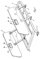
- Figure 1 with the reference numeral 1 is a head part referred to sick bed, not shown, on the On both long sides, a side rest 2 is pivotally connected is.
- Each side rest 2 is equipped with two pivot levers 3, the one hand pivotally connected to the side rest 2 and on the other hand on swivel bearings 4 attached to the bed side are rotatably mounted.
- the side rests 2 are together with the pivot levers 3 parallel to the axes of the pivot bearings 4 in predetermined Limits are displaceable relative to the head part 1, whereby through below the head part 1 and in the area of the pivot bearing 4 attached safety bracket 5 ensures that a Swiveling of the side rests 2 is only possible if the respective side back maximally with respect to the headboard frame 1 is pulled outwards as it is in this position Swivel lever 3 no longer in the blocking area of the safety bracket 5 lie.
- a bracket 9 is connected to each flange plate 7, namely via one on the respective flange disc 7 attached bolt 10, which in a corresponding Bore 11 of the bracket 9 engages.
- the bracket 9 is arranged above the axes 6 and in its end areas with downward jibs 12 provided within which the holes 11 and in these bores 11 engaging bolts 10 are arranged.
- the respective end positions of the swivel positions are additionally secured by a locking pin 13 which, depending on Swiveling position in one of the notches 8 already mentioned the flange 7 engages.
- This locking pin 13 is with an actuator 14 connected in the illustrated Exemplary embodiment from a in the side backrest 2 attached, vertically movable and with a handle opening 15 provided mold plate 16.
- This mold plate 16 can after previous actuation of a pawl 17 raised be, whereby the locking pin 13 out of engagement with the respective Notch 8 is coming.
- the illustrated Embodiment are a total of three positions lockable, namely the lower and the upper end position as well as an intermediate layer. But there is also the possibility the flange disc 7 to a certain extent with the circumference to provide a toothing, whereby a variety of possible Intermediate positions could be locked.
- a displacement of the mold plate by a closing device 18 16 can be prevented.
- the locking device 18 exists made of a rotatable disc that can be moved into the sliding area the molded plate 16 screwed in or out of this Can be turned out.
- the locking device 18 is advantageously designed such that that their operation only from outside the Bed is possible and also a tool or a key or the like. Thus, there are incorrect operations if necessary safe to avoid.
Landscapes
- Health & Medical Sciences (AREA)
- Nursing (AREA)
- Life Sciences & Earth Sciences (AREA)
- Animal Behavior & Ethology (AREA)
- General Health & Medical Sciences (AREA)
- Public Health (AREA)
- Veterinary Medicine (AREA)
- Invalid Beds And Related Equipment (AREA)
Description
- Figur 1
- eine perspektivische, schematische Darstellung eines Kopfteiles eines Krankenbettes mit daran angeschlossenen Seitenlehnen,
- Fiugr 2
- eine Seitenansicht einer Seitenlehne gemäß vorliegender Erfindung im nach unten geschwenkten Zustand,
- Figur 3
- eine Teilansicht in Richtung des Pfeiles III in Figur 2,
- Figur 4
- eine der Figur 2 entsprechende Seitenansicht im hochgeschwenkten Zustand der Seitenlehne, wobei durch strichpunktierte Linien eine mögliche Zwischenposition angedeutet ist,
- Figur 5
- einen Teilschnitt durch die Seitenlehne im Lagerbereich eines Schwenkhebels.
Claims (10)
- Seitenlehne (2) für ein Bett, insbesondere ein Krankenbett, mit zwei Schwenkhebeln (3), die einerseits schwenkbar an der Seitenlehne (2) angeschlossen und andererseits an bettseitig befestigten Schwenklagern (4) drehbar gelagert sind, wobei die Seitenlehne (2) gemeinsam mit den Schwenkhebeln (3) parallel zu den Schwenklagerachsen mit vobestimmten Grenzen relativ zum Bett verschiebbar und einerseits bis in eine untere Endstellung unterhalb der Liegefläche und andererseits bis in eine obere Endstellung oberhalb der Liegefläche verschwenkbar ist und die Schwenkhebel (3) ausschließlich in seitlich vollständig ausgeschobener Position verschwenkbar sind und daß die untere und die obere Endstellung der Seitenlehne (2) durch im Lagerbereich zwischen Seitenlehne (2) und Schwenkhebel (3) angeordnete Rastmittel gesichert ist, dadurch gekennzeichnet, daß die Rastmittel mit einer in der Seitenlehne (2) angeordneten Betätigungseinrichtung (14) verbunden sind.
- Seitenlehne nach Anspruch 1, dadurch gekennzeichnet, daß die Verschwenkung der Seitenlehne (2) und der Schwenkhebel (3) bei nicht vollständig ausgezogener Seitenlehne durch im Schwenklagerbereich (4) vorgesehene Sicherungsbügel (5) verhindert ist.
- Seitenlehne nach Anspruch 1 oder 2, dadurch gekennzeichnet, daß die Rastmittel aus einem mit der Betätigungseinrichtung verbundenen Rastbolzen (13) und aus einer mit einer Achse (6) eines Schwenkhebels (3) verbundenen und mit Einkerbungen (8) versehenen Flanschscheibe bestehen.
- Seitenlehne nach Anspruch 3, dadurch gekennzeichnet, daß die Betätigungseinrichtung (14) aus einer innerhalb der Seitenlehne (2) höhenbeweglichen Formscheibe (16) mit einer Grifföffnung (15) besteht.
- Seitenlehne nach Anspruch 4, dadurch gekennzeichnet, daß die höhenbewegliche Formscheibe (16) durch eine Sperrklinke (17) blockierbar ist.
- Seitenlehne nach einem oder mehreren der vorhergehenden Ansprüche, dadurch gekennzeichnet, daß die höhenbewegliche Formscheibe (16) durch eine Schließeinrichtung (18) vollständig blockierbar ist.
- Seitenlehne nach einem oder mehreren der vorhergehenden Ansprüche, dadurch gekennzeichnet, daß die Flanschscheibe (7) mit mindestens zwei Einkerbungen (8) ausgestattet ist.
- Seitenlehne nach einem oder mehreren der vorhergehenden Ansprüche, dadurch gekennzeichnet, daß jeder Schwenkhebel (3) mit einer an der Seitenlehne (2) gelagerten Achse (6) und einer verdrehfest mit der Achse (6) verbundenen Flanschscheibe (7) ausgestattet ist, und daß die beiden Flanschscheiben (7) über einen oberhalb der Achsen (6) liegenden Bügel (8) miteinander verbunden sind, wobei an den Flanschscheiben (7) jeweils ein Bolzen (10) vorgesehen ist, der in eine an einem nach unten gerichteten Ausleger (12) des Bügels (9) vorgesehene Bohrung (11) eingreift.
- Seitenlehne nach einem oder mehreren der vorhergehenden Ansprüche, dadurch gekennzeichnet, daß der Bügel (9) in einer möglichen Endstellung auf der Achse (6) des einen Schwenkhebels und in der anderen möglichen Endstellung auf der Achse (6) des anderen Schwenkhebels (3) aufliegt.
- Seitenlehne nach Anspruch 1, dadurch gekennzeichnet, daß die Betätigungseinrichtung (14) im oberen Randbereich der Seitenlehne (2) angeordnet ist.
Applications Claiming Priority (2)
| Application Number | Priority Date | Filing Date | Title |
|---|---|---|---|
| DE9407325U DE9407325U1 (de) | 1994-05-03 | 1994-05-03 | Seitenlehne für ein Bett, insbesondere ein Krankenbett |
| DE9407325U | 1994-05-03 |
Publications (2)
| Publication Number | Publication Date |
|---|---|
| EP0680714A1 EP0680714A1 (de) | 1995-11-08 |
| EP0680714B1 true EP0680714B1 (de) | 1999-09-29 |
Family
ID=6908159
Family Applications (1)
| Application Number | Title | Priority Date | Filing Date |
|---|---|---|---|
| EP95103913A Expired - Lifetime EP0680714B1 (de) | 1994-05-03 | 1995-03-17 | Seitenlehne für ein Bett, insbesondere ein Krankenbett |
Country Status (3)
| Country | Link |
|---|---|
| EP (1) | EP0680714B1 (de) |
| AT (1) | ATE185052T1 (de) |
| DE (2) | DE9407325U1 (de) |
Families Citing this family (5)
| Publication number | Priority date | Publication date | Assignee | Title |
|---|---|---|---|---|
| WO2003017905A2 (en) * | 2001-08-22 | 2003-03-06 | Hill-Rom Services, Inc. | Apparatus and method for closing hospital bed gaps |
| GB0226918D0 (en) * | 2002-11-19 | 2002-12-24 | Huntleigh Technology Plc | Panel assembly |
| FR2918256B1 (fr) | 2007-07-06 | 2009-10-09 | Hill Rom Sas Soc Par Actions S | Lit de malade a barriere laterale escamotable. |
| FR2918551A1 (fr) | 2007-07-13 | 2009-01-16 | Hill Rom Sas Soc Par Actions S | Lit a barriere laterale escamotable |
| FR2921550B1 (fr) | 2007-09-28 | 2013-03-29 | Hill Rom Sas | Lit a barriere laterale escamotable susceptible d'occuper plusieurs positions predeterminees |
Family Cites Families (2)
| Publication number | Priority date | Publication date | Assignee | Title |
|---|---|---|---|---|
| US3932903A (en) * | 1974-10-04 | 1976-01-20 | Hill-Rom Company, Inc. | Guard including electrical controls and slidable underneath the bed |
| US4747171A (en) * | 1986-08-12 | 1988-05-31 | Simmons Healthcare, Inc. | Hospital bed rail assembly |
-
1994
- 1994-05-03 DE DE9407325U patent/DE9407325U1/de not_active Expired - Lifetime
-
1995
- 1995-03-17 EP EP95103913A patent/EP0680714B1/de not_active Expired - Lifetime
- 1995-03-17 AT AT95103913T patent/ATE185052T1/de not_active IP Right Cessation
- 1995-03-17 DE DE59506925T patent/DE59506925D1/de not_active Expired - Fee Related
Also Published As
| Publication number | Publication date |
|---|---|
| ATE185052T1 (de) | 1999-10-15 |
| DE59506925D1 (de) | 1999-11-04 |
| DE9407325U1 (de) | 1994-08-11 |
| EP0680714A1 (de) | 1995-11-08 |
Similar Documents
| Publication | Publication Date | Title |
|---|---|---|
| EP0617947A1 (de) | Drehteller für Behinderte | |
| DE10260826A1 (de) | Sitzvorrichtung | |
| DE102007040572B3 (de) | Verriegelungsvorrichtung und dafür geeignete Betätigungseinheit | |
| DE1429271A1 (de) | Einstellbares Bett | |
| DE19900602C1 (de) | Seitengitter für ein Kranken- oder Pflegebett | |
| EP0680714B1 (de) | Seitenlehne für ein Bett, insbesondere ein Krankenbett | |
| EP0875181B1 (de) | Sitzmöbel | |
| DE2810119A1 (de) | Gelenkverbindung, insbesondere fuer fahrzeugsitze | |
| EP0808757B1 (de) | Sessel von Sesselliften mit einer Fallschutzeinrichtung | |
| DE3020654A1 (de) | Krankenbett | |
| DE102006051289B4 (de) | Sitzmöbel | |
| EP1417910B1 (de) | Beschlag für Sitz- bzw. Liegemöbel | |
| DE2002930A1 (de) | Verriegelbare Geraeteabdeckvorrichtung | |
| AT390178B (de) | Verstellbares liegemoebel, insbesondere bett | |
| DE2725493A1 (de) | Rollstuhl mit verschwenkbarer beinstuetze | |
| AT398691B (de) | Sitz- und liegemöbel | |
| DE202014104570U1 (de) | Sitz- und Liegemöbel | |
| EP0520267B1 (de) | Verfahren zum Steuern einer Hubeinrichtung und Hubeinrichtung für bewegungsbehinderte Menschen | |
| DE927007C (de) | Betaetigungsvorrichtung fuer das Verschlussventil von Druckmittelbehaeltern, insbesondere von Loeschmittelbehaeltern | |
| EP0684030B1 (de) | Sessel mit Aufstehhilfe | |
| DE60210038T2 (de) | Selektive Sperrvorrichtung für Schubladen mit Kippschutz | |
| DE2701165C2 (de) | Matratzenrahmen für Betten | |
| DE3232257A1 (de) | Feststellbare lenkrolle fuer verfahrbare geraete, insbesondere muell- o. dgl. -behaelter | |
| EP1174106A2 (de) | Mit schwenkbaren Seitenlehnen versehenes Kranken- oder Pflegebett | |
| EP2130458B1 (de) | Beschlag für ein Sitz- und/oder Liegemöbel |
Legal Events
| Date | Code | Title | Description |
|---|---|---|---|
| PUAI | Public reference made under article 153(3) epc to a published international application that has entered the european phase |
Free format text: ORIGINAL CODE: 0009012 |
|
| AK | Designated contracting states |
Kind code of ref document: A1 Designated state(s): AT BE CH DE FR GB LI LU NL |
|
| 17P | Request for examination filed |
Effective date: 19960320 |
|
| 17Q | First examination report despatched |
Effective date: 19980313 |
|
| GRAG | Despatch of communication of intention to grant |
Free format text: ORIGINAL CODE: EPIDOS AGRA |
|
| GRAG | Despatch of communication of intention to grant |
Free format text: ORIGINAL CODE: EPIDOS AGRA |
|
| GRAG | Despatch of communication of intention to grant |
Free format text: ORIGINAL CODE: EPIDOS AGRA |
|
| GRAH | Despatch of communication of intention to grant a patent |
Free format text: ORIGINAL CODE: EPIDOS IGRA |
|
| GRAH | Despatch of communication of intention to grant a patent |
Free format text: ORIGINAL CODE: EPIDOS IGRA |
|
| GRAA | (expected) grant |
Free format text: ORIGINAL CODE: 0009210 |
|
| AK | Designated contracting states |
Kind code of ref document: B1 Designated state(s): AT BE CH DE FR GB LI LU NL |
|
| REF | Corresponds to: |
Ref document number: 185052 Country of ref document: AT Date of ref document: 19991015 Kind code of ref document: T |
|
| REG | Reference to a national code |
Ref country code: CH Ref legal event code: NV Representative=s name: ISLER & PEDRAZZINI AG Ref country code: CH Ref legal event code: EP |
|
| GBT | Gb: translation of ep patent filed (gb section 77(6)(a)/1977) |
Effective date: 19990929 |
|
| REF | Corresponds to: |
Ref document number: 59506925 Country of ref document: DE Date of ref document: 19991104 |
|
| ET | Fr: translation filed | ||
| PLBE | No opposition filed within time limit |
Free format text: ORIGINAL CODE: 0009261 |
|
| STAA | Information on the status of an ep patent application or granted ep patent |
Free format text: STATUS: NO OPPOSITION FILED WITHIN TIME LIMIT |
|
| 26N | No opposition filed | ||
| PGFP | Annual fee paid to national office [announced via postgrant information from national office to epo] |
Ref country code: FR Payment date: 20010319 Year of fee payment: 7 |
|
| PGFP | Annual fee paid to national office [announced via postgrant information from national office to epo] |
Ref country code: BE Payment date: 20010323 Year of fee payment: 7 Ref country code: AT Payment date: 20010323 Year of fee payment: 7 |
|
| PGFP | Annual fee paid to national office [announced via postgrant information from national office to epo] |
Ref country code: NL Payment date: 20010326 Year of fee payment: 7 |
|
| PGFP | Annual fee paid to national office [announced via postgrant information from national office to epo] |
Ref country code: LU Payment date: 20010327 Year of fee payment: 7 |
|
| PGFP | Annual fee paid to national office [announced via postgrant information from national office to epo] |
Ref country code: GB Payment date: 20010403 Year of fee payment: 7 |
|
| PGFP | Annual fee paid to national office [announced via postgrant information from national office to epo] |
Ref country code: CH Payment date: 20010423 Year of fee payment: 7 |
|
| REG | Reference to a national code |
Ref country code: GB Ref legal event code: IF02 |
|
| PG25 | Lapsed in a contracting state [announced via postgrant information from national office to epo] |
Ref country code: LU Free format text: LAPSE BECAUSE OF NON-PAYMENT OF DUE FEES Effective date: 20020317 Ref country code: GB Free format text: LAPSE BECAUSE OF NON-PAYMENT OF DUE FEES Effective date: 20020317 Ref country code: AT Free format text: LAPSE BECAUSE OF NON-PAYMENT OF DUE FEES Effective date: 20020317 |
|
| PG25 | Lapsed in a contracting state [announced via postgrant information from national office to epo] |
Ref country code: LI Free format text: LAPSE BECAUSE OF NON-PAYMENT OF DUE FEES Effective date: 20020331 Ref country code: CH Free format text: LAPSE BECAUSE OF NON-PAYMENT OF DUE FEES Effective date: 20020331 Ref country code: BE Free format text: LAPSE BECAUSE OF NON-PAYMENT OF DUE FEES Effective date: 20020331 |
|
| BERE | Be: lapsed |
Owner name: JOH. *STIEGELMEYER G.M.B.H. & CO. K.G. Effective date: 20020331 |
|
| PG25 | Lapsed in a contracting state [announced via postgrant information from national office to epo] |
Ref country code: NL Free format text: LAPSE BECAUSE OF NON-PAYMENT OF DUE FEES Effective date: 20021001 |
|
| GBPC | Gb: european patent ceased through non-payment of renewal fee |
Effective date: 20020317 |
|
| REG | Reference to a national code |
Ref country code: CH Ref legal event code: PL |
|
| PG25 | Lapsed in a contracting state [announced via postgrant information from national office to epo] |
Ref country code: FR Free format text: LAPSE BECAUSE OF NON-PAYMENT OF DUE FEES Effective date: 20021129 |
|
| NLV4 | Nl: lapsed or anulled due to non-payment of the annual fee |
Effective date: 20021001 |
|
| REG | Reference to a national code |
Ref country code: FR Ref legal event code: ST |
|
| PGFP | Annual fee paid to national office [announced via postgrant information from national office to epo] |
Ref country code: DE Payment date: 20060516 Year of fee payment: 12 |
|
| PG25 | Lapsed in a contracting state [announced via postgrant information from national office to epo] |
Ref country code: DE Free format text: LAPSE BECAUSE OF NON-PAYMENT OF DUE FEES Effective date: 20071002 |