EP0675322A2 - Brûleur à prémélange - Google Patents
Brûleur à prémélange Download PDFInfo
- Publication number
- EP0675322A2 EP0675322A2 EP95810184A EP95810184A EP0675322A2 EP 0675322 A2 EP0675322 A2 EP 0675322A2 EP 95810184 A EP95810184 A EP 95810184A EP 95810184 A EP95810184 A EP 95810184A EP 0675322 A2 EP0675322 A2 EP 0675322A2
- Authority
- EP
- European Patent Office
- Prior art keywords
- channel
- flow
- vortex generator
- vortex
- premix burner
- Prior art date
- Legal status (The legal status is an assumption and is not a legal conclusion. Google has not performed a legal analysis and makes no representation as to the accuracy of the status listed.)
- Granted
Links
Images
Classifications
-
- F—MECHANICAL ENGINEERING; LIGHTING; HEATING; WEAPONS; BLASTING
- F23—COMBUSTION APPARATUS; COMBUSTION PROCESSES
- F23D—BURNERS
- F23D23/00—Assemblies of two or more burners
-
- F—MECHANICAL ENGINEERING; LIGHTING; HEATING; WEAPONS; BLASTING
- F23—COMBUSTION APPARATUS; COMBUSTION PROCESSES
- F23D—BURNERS
- F23D11/00—Burners using a direct spraying action of liquid droplets or vaporised liquid into the combustion space
- F23D11/36—Details, e.g. burner cooling means, noise reduction means
- F23D11/40—Mixing tubes or chambers; Burner heads
- F23D11/402—Mixing chambers downstream of the nozzle
-
- F—MECHANICAL ENGINEERING; LIGHTING; HEATING; WEAPONS; BLASTING
- F23—COMBUSTION APPARATUS; COMBUSTION PROCESSES
- F23D—BURNERS
- F23D14/00—Burners for combustion of a gas, e.g. of a gas stored under pressure as a liquid
- F23D14/20—Non-premix gas burners, i.e. in which gaseous fuel is mixed with combustion air on arrival at the combustion zone
- F23D14/22—Non-premix gas burners, i.e. in which gaseous fuel is mixed with combustion air on arrival at the combustion zone with separate air and gas feed ducts, e.g. with ducts running parallel or crossing each other
-
- F—MECHANICAL ENGINEERING; LIGHTING; HEATING; WEAPONS; BLASTING
- F05—INDEXING SCHEMES RELATING TO ENGINES OR PUMPS IN VARIOUS SUBCLASSES OF CLASSES F01-F04
- F05B—INDEXING SCHEME RELATING TO WIND, SPRING, WEIGHT, INERTIA OR LIKE MOTORS, TO MACHINES OR ENGINES FOR LIQUIDS COVERED BY SUBCLASSES F03B, F03D AND F03G
- F05B2240/00—Components
- F05B2240/10—Stators
- F05B2240/12—Fluid guiding means, e.g. vanes
- F05B2240/122—Vortex generators, turbulators, or the like, for mixing
Definitions
- the invention relates to a premix burner, consisting essentially of a pilot burner and a plurality of main burners arranged around the pilot burner.
- the mixing of fuel into a combustion air flow flowing in a premixing duct is usually done by radial injection of the fuel into the duct by means of cross jet mixers.
- the momentum of the fuel is so low that an almost complete mixing takes place only after a distance of approximately 100 channel heights.
- Venturi mixers are also used.
- the injection of the fuel via grid arrangements is also known.
- spraying in front of special swirl bodies is also used.
- the devices operating on the basis of transverse jets or stratified flows either result in very long mixing distances or require high injection pulses.
- premixing under high pressure and substoichiometric mixing ratios there is a risk of the flame flashing back or even of self-ignition of the mixture.
- Flow separations and dead water zones in the premixing tube, thick boundary layers on the walls or possibly extreme speed profiles over the cross-section through which the flow is flowing can be the cause of auto-ignition in the tube or form paths through which the flame can strike back from the downstream combustion zone into the premixing tube.
- the geometry of the premixing section must therefore be given the greatest attention.
- premixing burners of the double-cone type can be designated as flame-holding burners.
- Such double-cone burners are known, for example, from EP-B1-0 321 809 and are described later in relation to FIGS. 1 and 3.
- the fuel, there natural gas, is injected into the combustion air flowing in from the compressor through a series of injector nozzles. As a rule, these are evenly distributed over the entire gap.
- the invention is therefore based on the object of providing a measure for a premix burner of the type mentioned at the outset, with which intimate mixing of combustion air and fuel is achieved within a very short distance while at the same time distributing the speed uniformly in the mixing zone. Furthermore, with such a burner, the flame should certainly be prevented from kicking back without using a mechanical flame holder.
- the measure should also be suitable for retrofitting existing premix combustion chambers.
- the new static mixer which is represented by the 3-dimensional vortex generators, it is possible to achieve extremely short mixing distances in the burner with a low pressure drop. Due to the generation of longitudinal vortices without a recirculation area, a coarse mixing of the two streams takes place after a full vortex revolution, while fine mixing as a result of turbulence Flow and molecular diffusion processes already exist after a distance that corresponds to a few channel heights.
- This type of mixture is particularly suitable for mixing the fuel into the combustion air at a relatively low admission pressure and with great dilution.
- a low admission pressure of the fuel is particularly advantageous when using medium and low calorific fuel gases.
- the energy required for mixing is largely drawn from the flow energy of the fluid with the higher volume flow, namely the combustion air.
- the downstream arrangement of a Venturi nozzle behind the vortex generators has the advantage that, with the largest constriction of the Venturi nozzle, one has a simple means in hand to introduce the fuel into the swirled flow with the least counter pressure.
- the correct dimensioning of the Venturi nozzle also has the advantage that the flow velocity therein exceeds the flame velocity, so that the flame cannot strike back into the injection plane of the fuel.
- the vortex generators upstream of the Venturi nozzle are characterized by a roof surface and two side surfaces, the side surfaces being flush with the same duct wall and including an arrow angle ⁇ with one another, and the longitudinal edges of the roof surface being flush with the longitudinal edges of the roof protruding into the flow duct Side surfaces and at an angle of attack ⁇ to the duct wall.
- the advantage of such vortex generators can be seen in their particular simplicity in every respect.
- Manufacturing technology the element consisting of three flow-around walls is completely problem-free.
- the roof surface can be joined with the two side surfaces in a variety of ways.
- the element can also be fixed to flat or curved channel walls in the case of weldable materials by simple weld seams. From a fluidic point of view, the element has a very low pressure drop when flowing around and it creates vortices without a dead water area.
- the element due to its generally hollow interior, the element can be cooled in a variety of ways and with various means.
- the two side surfaces enclosing the arrow angle ⁇ form an at least approximately sharp connecting edge with one another, which together with the longitudinal edges of the roof surface forms a tip, the flow cross-section is hardly impaired by blocking.
- the sharp connecting edge is the exit-side edge of the vortex generator and it runs perpendicular to the channel wall with which the side surfaces are flush, then the non-formation of a wake area is advantageous.
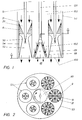
- 53 denotes a cylindrical burner wall. It is connected on the outlet side to the front wall 100 of the combustion chamber (not shown) by suitable means.
- This combustion chamber can be either an annular combustion chamber or a silo combustion chamber, with several such burners being arranged on the front wall 100 in each case.
- main burners 52 are grouped around a centrally arranged pilot burner 101.
- the pilot burner is a premix burner of the double-cone type, although this is not mandatory. It is important that this pilot burner should have the smallest possible geometry. About 10-30% of the fuel should be burned in it.
- the main burners 52 are cylindrical in shape.
- vortex generators 9 are initially arranged in the direction of flow, the outlet of which opens into a Venturi nozzle 50.
- the fuel is supplied to the pilot burner and the main burners via fuel lances 120 and 51, respectively.
- the combustion air flows from a plenum, not shown, into the housing interior 103, from where it flows into the burners 101, 52 in the direction of the arrow.
- the schematically illustrated premix burner 101 according to FIGS. 1, 3A and 3B is a so-called double-cone burner, as is known for example from EP-B1-0 321 809. It essentially consists of two hollow, conical partial bodies 111, 112 which are nested one inside the other in the direction of flow. The respective central axes 113, 114 of the two partial bodies are offset from one another. The adjacent walls of the two partial bodies in their longitudinal extent form tangential slots 119 for the combustion air, which in this way reaches the interior of the burner. A first fuel nozzle 116 for liquid fuel is arranged there. The fuel is injected into the hollow cone at an acute angle. The resulting conical fuel profile is enclosed by the combustion air flowing in tangentially.
- the concentration of the fuel is continuously reduced in the axial direction due to the mixing with the combustion air.
- the burner is also operated with gaseous fuel.
- gas inflow openings 117 distributed in the longitudinal direction are provided in the region of the tangential slots 119 in the walls of the two partial bodies.
- the mixture formation with the combustion air thus begins in the zone of the inlet slots 20. It goes without saying that mixed operation with both types of fuel is also possible in this way.
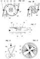
- a vortex generator essentially consists of three free-flowing triangular surfaces. These are a roof surface 10 and two side surfaces 11 and 13. In their longitudinal extent, these surfaces run at certain angles in the direction of flow.
- the side walls of the vortex generator which consist of right-angled triangles, are fixed with their long sides on a channel wall 21, preferably gas-tight. They are oriented so that they form a joint on their narrow sides, including an arrow angle ⁇ .
- the joint is designed as a sharp connecting edge 16 and is perpendicular to that channel wall 21 with which the side surfaces are flush.
- the two side surfaces 11, 13 including the arrow angle ⁇ are symmetrical in shape, size and orientation in FIG. 4 and are arranged on both sides of an axis of symmetry 17. This axis of symmetry 17 is rectified like the channel axis.
- the roof surface 10 lies with a very narrow edge 15 running transversely to the flow through the channel on the same channel wall 21 as the side walls 11, 13. Its longitudinal edges 12, 14 are flush with the longitudinal edges of the side surfaces projecting into the flow channel.
- the roof area runs under one Angle of attack ⁇ to the channel wall 21. Their longitudinal edges 12, 14 together with the connecting edge 16 form a tip 18.
- the vortex generator can also be provided with a bottom surface with which it is fastened in a suitable manner to the channel wall 21.
- a floor area is not related to the mode of operation of the element.
- the connecting edge 16 of the two side surfaces 11, 13 forms the downstream edge of the vortex generator.
- the edge 15 of the roof surface 10 which runs transversely to the flow through the channel is thus the edge which is first acted upon by the channel flow.
- the vortex generator works as follows: When flowing around edges 12 and 14, the main flow is converted into a pair of opposing vortices. Their vortex axes lie in the axis of the main flow. The number of swirls and the location of the vortex breakdown (if the latter is desired at all) are determined by appropriate selection of the angle of attack ⁇ and the arrow angle ⁇ . With increasing angles, the vortex strength or the number of swirls is increased and the location of the vortex burst moves upstream into the area of the vortex generator itself. Depending on the application, these two angles ⁇ and ⁇ are predetermined by the structural conditions and by the process itself. Then only the length L of the element and the height h of the connecting edge 16 need to be adjusted (FIG. 7).
- FIG. 5 shows a so-called half "vortex generator" based on a vortex generator according to FIG. 1, in which only one of the two side surfaces of the vortex generator 9a is provided with the arrow angle ⁇ / 2.
- the other side surface is straight and oriented in the direction of flow.
- only one vortex is generated on the arrowed side. Accordingly, there is no vortex-neutral field downstream of the vortex generator, but a swirl is forced on the flow.
- the sharp connecting edge 16 of the vortex generator 9 in FIG. 6 is the point which is first acted upon by the channel flow.
- the element is rotated by 180 °.
- the two opposite vortices have changed their sense of rotation.
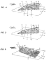
- the vortex generators are installed in a channel 20.
- the height h of the connecting edge 16 will be coordinated with the channel height H - or the height of the channel part which is assigned to the vortex generator - in such a way that the vortex generated immediately downstream of the vortex generator already reaches such a size that the full channel height H is filled. This leads to a uniform speed distribution in the cross-section applied.
- Another criterion that can influence the ratio h / H to be selected is the pressure drop that occurs when the vortex generator flows around. It goes without saying that the pressure loss coefficient also increases with a larger ratio h / H.
- four vortex generators 9 are distributed at a distance over the circumference of the circular cross section according to FIG.
- the above-mentioned height of the channel part, which is assigned to the individual vortex generator, corresponds in this case to the circle radius.
- the four vortex generators 9 could also be strung together on their respective wall segments 21 in the circumferential direction in such a way that no gaps are left free on the channel wall.
- the vortex to be generated is decisive here.
- the vortex generators 9 are mainly used for mixing two flows.
- the main flow in the form of combustion air attacks the transverse inlet edges 15 in the direction of the arrow.
- the secondary flow in the form of a gaseous and / or liquid fuel has a substantially smaller mass flow than the main flow. In the present case, it is introduced into the main flow downstream of the vortex generators.
- the fuel is injected here via a central fuel lance 51, the mouth of which is located downstream of the vortex generators. This lance is dimensioned for about 10% of the total volume flow through channel 20.
- a longitudinal injection of the fuel in the flow direction is shown. In this case, the injection pulse corresponds approximately to that of the main flow pulse.
- a cross-jet injection could be provided just as well, the fuel pulse then having to be approximately twice that of the main flow.
- the injected fuel is dragged along by the vortices and mixed with the main flow. It follows the helical course of the vortices and is evenly and finely distributed in the chamber downstream of the vortices. This reduces the risk of impinging jets on the opposite wall and the formation of so-called "hot spots" - in the case of the radial injection of fuel into an undisturbed flow mentioned at the beginning.
- the fuel injection can be kept flexible and adapted to other boundary conditions. In this way, the same injection pulse can be maintained throughout the load range. Since mixing through the The geometry of the vortex generators is determined, and not by the machine load, in the example the gas turbine output, the burner configured in this way works optimally even under partial load conditions.
- the combustion process is optimized by adjusting the ignition delay time of the fuel and mixing time of the vortices, which ensures a minimization of emissions.
- thermoacoustic instability Due to their presence alone, the vortex generators act as a damping measure against thermoacoustic vibrations.
- a Venturi nozzle 52 is provided downstream of the vortex generators. This is dimensioned so that at an exit speed of approximately 80-150 m / sec the flow velocity in the narrowest cross section is approximately 150-180 m / sec. The distance of the narrowest cross section to the trailing edges 16 of the vortex generators will be chosen so that the generated vertebrae are already fully formed in the narrowest cross section. The location of the fuel injection is at the level of the largest constriction of the Venturi nozzle.
- FIGS. 8 and 9 show a top view of an embodiment variant of the vortex generator and a front view of its arrangement in a circular channel.
- the two side surfaces 11 and 13 enclosing the arrow angle ⁇ have a different length.
- the vortex generator then naturally has a different width Angle of attack ⁇ on.
- Such a variant has the effect that vortices with different strengths are generated. For example, this can act on a swirl adhering to the main flow. Or, due to the different vortices, a swirl is forced on the originally swirl-free main flow downstream of the vortex generators, as is indicated in FIG. 9.
- Such a configuration works well as an independent, compact burner unit.
- the swirl imposed on the main flow can be used to improve the cross-ignition behavior of the burner configuration, for example at partial load.
- the secondary flow can also be introduced into the main flow in a variety of ways, for example only or additionally via wall bores in the venturi tube
Landscapes
- Engineering & Computer Science (AREA)
- Chemical & Material Sciences (AREA)
- Combustion & Propulsion (AREA)
- Mechanical Engineering (AREA)
- General Engineering & Computer Science (AREA)
- Gas Burners (AREA)
- Spray-Type Burners (AREA)
Applications Claiming Priority (2)
| Application Number | Priority Date | Filing Date | Title |
|---|---|---|---|
| DE4411622A DE4411622A1 (de) | 1994-04-02 | 1994-04-02 | Vormischbrenner |
| DE4411622 | 1994-04-02 |
Publications (3)
| Publication Number | Publication Date |
|---|---|
| EP0675322A2 true EP0675322A2 (fr) | 1995-10-04 |
| EP0675322A3 EP0675322A3 (fr) | 1996-05-15 |
| EP0675322B1 EP0675322B1 (fr) | 1999-04-28 |
Family
ID=6514606
Family Applications (1)
| Application Number | Title | Priority Date | Filing Date |
|---|---|---|---|
| EP95810184A Expired - Lifetime EP0675322B1 (fr) | 1994-04-02 | 1995-03-17 | Brûleur à prémélange |
Country Status (5)
| Country | Link |
|---|---|
| US (1) | US5558515A (fr) |
| EP (1) | EP0675322B1 (fr) |
| JP (1) | JPH07280224A (fr) |
| CN (1) | CN1118858A (fr) |
| DE (2) | DE4411622A1 (fr) |
Cited By (2)
| Publication number | Priority date | Publication date | Assignee | Title |
|---|---|---|---|---|
| WO2008051115A1 (fr) * | 2006-10-25 | 2008-05-02 | Kukanov, Vyacheslav Alekseevich | Procédé et dispositif d'échanges de chaleur, de masse et d'énergie |
| EP2112433A1 (fr) * | 2008-04-23 | 2009-10-28 | Siemens Aktiengesellschaft | Chambre de mélange |
Families Citing this family (37)
| Publication number | Priority date | Publication date | Assignee | Title |
|---|---|---|---|---|
| DE19510744A1 (de) * | 1995-03-24 | 1996-09-26 | Abb Management Ag | Brennkammer mit Zweistufenverbrennung |
| JP3492099B2 (ja) * | 1995-10-03 | 2004-02-03 | 三菱重工業株式会社 | バーナ |
| US5927076A (en) * | 1996-10-22 | 1999-07-27 | Westinghouse Electric Corporation | Multiple venturi ultra-low nox combustor |
| DE69919764T2 (de) * | 1998-02-09 | 2005-09-01 | Mitsubishi Heavy Industries, Ltd. | Brennkammer |
| DE19948673B4 (de) * | 1999-10-08 | 2009-02-26 | Alstom | Verfahren zum Erzeugen von heissen Gasen in einer Verbrennungseinrichtung sowie Verbrennungseinrichtung zur Durchführung des Verfahrens |
| EP1096201A1 (fr) | 1999-10-29 | 2001-05-02 | Siemens Aktiengesellschaft | Brûleur |
| JP2001254946A (ja) | 2000-03-14 | 2001-09-21 | Mitsubishi Heavy Ind Ltd | ガスタービン燃焼器 |
| DE10108560A1 (de) * | 2001-02-22 | 2002-09-05 | Alstom Switzerland Ltd | Verfahren zum Betrieb einer Ringbrennkammer sowie eine diesbezügliche Ringbrennkammer |
| GB2375601A (en) * | 2001-05-18 | 2002-11-20 | Siemens Ag | Burner apparatus for reducing combustion vibrations |
| JP4508474B2 (ja) * | 2001-06-07 | 2010-07-21 | 三菱重工業株式会社 | 燃焼器 |
| DE10330023A1 (de) * | 2002-07-20 | 2004-02-05 | Alstom (Switzerland) Ltd. | Wirbelgenerator mit kontrollierter Nachlaufströmung |
| GB2398375A (en) * | 2003-02-14 | 2004-08-18 | Alstom | A mixer for two fluids having a venturi shape |
| US7407381B2 (en) * | 2003-10-21 | 2008-08-05 | Pac, Lp | Combustion apparatus and methods for making and using same |
| KR100645604B1 (ko) * | 2005-11-29 | 2006-11-14 | 한국항공우주연구원 | 스월혼합장치 |
| FR2903479A1 (fr) * | 2006-07-06 | 2008-01-11 | Air Liquide | Bruleur a flamme orientable et procede de mise en oeuvre |
| WO2008091801A2 (fr) * | 2007-01-22 | 2008-07-31 | Rolls-Royce Fuel Cell Systems Inc. | Chambre de combustion à étages et procédé de démarrage d'un système pile à combustible |
| GB2449267A (en) * | 2007-05-15 | 2008-11-19 | Alstom Technology Ltd | Cool diffusion flame combustion |
| EP2629011A1 (fr) * | 2008-09-29 | 2013-08-21 | Siemens Aktiengesellschaft | Buse de combustible |
| DE102008053755A1 (de) | 2008-10-28 | 2010-04-29 | Pfeifer, Uwe, Dr. | Register Pilotbrennersystem für Gasturbinen |
| BRPI1006158A2 (pt) | 2009-01-16 | 2016-02-23 | Air Prod & Chem | dispositivo de combustão, método para combustão de pelo menos um dentre combustíveis gasosos e líquidos, e kit para um dispositivo de combustão |
| ES2462974T3 (es) | 2010-08-16 | 2014-05-27 | Alstom Technology Ltd | Quemador de recalentamiento |
| US8893500B2 (en) | 2011-05-18 | 2014-11-25 | Solar Turbines Inc. | Lean direct fuel injector |
| US8919132B2 (en) | 2011-05-18 | 2014-12-30 | Solar Turbines Inc. | Method of operating a gas turbine engine |
| US9182124B2 (en) | 2011-12-15 | 2015-11-10 | Solar Turbines Incorporated | Gas turbine and fuel injector for the same |
| US8967997B2 (en) | 2012-02-13 | 2015-03-03 | Factory Mutual Insurance Company | System and components for evaluating the performance of fire safety protection devices |
| US9694223B2 (en) | 2012-02-13 | 2017-07-04 | Factory Mutual Insurance Company | System and components for evaluating the performance of fire safety protection devices |
| US9285120B2 (en) | 2012-10-06 | 2016-03-15 | Coorstek, Inc. | Igniter shield device and methods associated therewith |
| CN102954468B (zh) * | 2012-11-27 | 2015-04-08 | 薛垂义 | 光亮罩式退火炉用烧嘴 |
| US20150159878A1 (en) * | 2013-12-11 | 2015-06-11 | Kai-Uwe Schildmacher | Combustion system for a gas turbine engine |
| JP6177187B2 (ja) * | 2014-04-30 | 2017-08-09 | 三菱日立パワーシステムズ株式会社 | ガスタービン燃焼器、ガスタービン、制御装置及び制御方法 |
| EP3081862B1 (fr) * | 2015-04-13 | 2020-08-19 | Ansaldo Energia Switzerland AG | Agencement de génération de vortex pour un brûleur à pré-mélange d'une turbine à gaz et turbine à gaz avec un tel agencement de génération de vortex |
| CN104896511B (zh) * | 2015-05-29 | 2017-03-22 | 北京航空航天大学 | 一种用于低排放燃烧室的燃油预混装置 |
| CN105240847A (zh) * | 2015-11-19 | 2016-01-13 | 哈尔滨东安发动机(集团)有限公司 | 一种燃烧室防回火结构 |
| EP3236157A1 (fr) | 2016-04-22 | 2017-10-25 | Siemens Aktiengesellschaft | Générateur de tourbillonnement pour mélanger un combustible avec de l'air dans un moteur à combustion |
| GB201808817D0 (en) * | 2018-05-30 | 2018-07-11 | Ideal Boilers Ltd | Gas boiler intake system |
| CN113405093A (zh) * | 2021-05-06 | 2021-09-17 | 中国科学院工程热物理研究所 | 燃料喷口、燃烧装置及燃烧控制方法 |
| US11454396B1 (en) * | 2021-06-07 | 2022-09-27 | General Electric Company | Fuel injector and pre-mixer system for a burner array |
Citations (7)
| Publication number | Priority date | Publication date | Assignee | Title |
|---|---|---|---|---|
| DE3520772A1 (de) * | 1985-06-10 | 1986-12-11 | INTERATOM GmbH, 5060 Bergisch Gladbach | Mischvorrichtung |
| DE3534268A1 (de) * | 1985-09-26 | 1987-04-02 | Deutsche Forsch Luft Raumfahrt | Zur vermeidung von stroemungsabloesungen ausgebildete oberflaeche eines umstroemten koerpers |
| EP0397046A2 (fr) * | 1989-05-11 | 1990-11-14 | Mitsubishi Jukogyo Kabushiki Kaisha | Brûleur |
| EP0321809B1 (fr) * | 1987-12-21 | 1991-05-15 | BBC Brown Boveri AG | Procédé pour la combustion de combustible liquide dans un brûleur |
| EP0478305A2 (fr) * | 1990-09-26 | 1992-04-01 | Hitachi, Ltd. | Chambre de combustion et appareil à combustion |
| EP0619457A1 (fr) * | 1993-04-08 | 1994-10-12 | ABB Management AG | Brûleur à prémélange |
| EP0623786A1 (fr) * | 1993-04-08 | 1994-11-09 | ABB Management AG | Chambre de combustion |
Family Cites Families (3)
| Publication number | Priority date | Publication date | Assignee | Title |
|---|---|---|---|---|
| JP2772955B2 (ja) * | 1988-07-08 | 1998-07-09 | 株式会社日本ケミカル・プラント・コンサルタント | 燃焼器用の燃料混合器 |
| CH679692A5 (fr) * | 1989-04-24 | 1992-03-31 | Asea Brown Boveri | |
| EP0548396B1 (fr) * | 1991-12-23 | 1995-02-22 | Asea Brown Boveri Ag | Dispositif servant à mélanger deux composants gazeux et brûleur dans lequel ce dispositif est appliqué |
-
1994
- 1994-04-02 DE DE4411622A patent/DE4411622A1/de not_active Withdrawn
-
1995
- 1995-03-06 US US08/399,143 patent/US5558515A/en not_active Expired - Fee Related
- 1995-03-17 DE DE59505747T patent/DE59505747D1/de not_active Expired - Fee Related
- 1995-03-17 EP EP95810184A patent/EP0675322B1/fr not_active Expired - Lifetime
- 1995-04-01 CN CN95103846A patent/CN1118858A/zh active Pending
- 1995-04-03 JP JP7077962A patent/JPH07280224A/ja active Pending
Patent Citations (7)
| Publication number | Priority date | Publication date | Assignee | Title |
|---|---|---|---|---|
| DE3520772A1 (de) * | 1985-06-10 | 1986-12-11 | INTERATOM GmbH, 5060 Bergisch Gladbach | Mischvorrichtung |
| DE3534268A1 (de) * | 1985-09-26 | 1987-04-02 | Deutsche Forsch Luft Raumfahrt | Zur vermeidung von stroemungsabloesungen ausgebildete oberflaeche eines umstroemten koerpers |
| EP0321809B1 (fr) * | 1987-12-21 | 1991-05-15 | BBC Brown Boveri AG | Procédé pour la combustion de combustible liquide dans un brûleur |
| EP0397046A2 (fr) * | 1989-05-11 | 1990-11-14 | Mitsubishi Jukogyo Kabushiki Kaisha | Brûleur |
| EP0478305A2 (fr) * | 1990-09-26 | 1992-04-01 | Hitachi, Ltd. | Chambre de combustion et appareil à combustion |
| EP0619457A1 (fr) * | 1993-04-08 | 1994-10-12 | ABB Management AG | Brûleur à prémélange |
| EP0623786A1 (fr) * | 1993-04-08 | 1994-11-09 | ABB Management AG | Chambre de combustion |
Cited By (3)
| Publication number | Priority date | Publication date | Assignee | Title |
|---|---|---|---|---|
| WO2008051115A1 (fr) * | 2006-10-25 | 2008-05-02 | Kukanov, Vyacheslav Alekseevich | Procédé et dispositif d'échanges de chaleur, de masse et d'énergie |
| EP2112433A1 (fr) * | 2008-04-23 | 2009-10-28 | Siemens Aktiengesellschaft | Chambre de mélange |
| US8424310B2 (en) | 2008-04-23 | 2013-04-23 | Siemens Aktiengesellschaft | Mixing chamber |
Also Published As
| Publication number | Publication date |
|---|---|
| DE59505747D1 (de) | 1999-06-02 |
| CN1118858A (zh) | 1996-03-20 |
| US5558515A (en) | 1996-09-24 |
| JPH07280224A (ja) | 1995-10-27 |
| DE4411622A1 (de) | 1995-10-05 |
| EP0675322B1 (fr) | 1999-04-28 |
| EP0675322A3 (fr) | 1996-05-15 |
Similar Documents
| Publication | Publication Date | Title |
|---|---|---|
| EP0675322B1 (fr) | Brûleur à prémélange | |
| EP0619457B1 (fr) | Brûleur à prémélange | |
| EP0623786B1 (fr) | Chambre de combustion | |
| EP0619456B1 (fr) | Système d'alimentation en carburant pour chambre de combustion | |
| EP0733861A2 (fr) | Chambre de combustion à combustion étagée | |
| DE4426351B4 (de) | Brennkammer für eine Gasturbine | |
| DE69210715T2 (de) | Brenner mit geringer NOx-Produktion | |
| DE60007946T2 (de) | Eine Brennkammer | |
| EP0918191B1 (fr) | Brûleur pour la mise en oeuvre d'un générateur de chaleur | |
| EP0620403B1 (fr) | Dispositif de mélange et de stabilisation de la flamme dans une chambre de combustion avec mélange préalable du combustible. | |
| DE4411623A1 (de) | Vormischbrenner | |
| DE4417538A1 (de) | Brennkammer mit Selbstzündung | |
| WO2008155373A1 (fr) | Stabilisation sans rotation de la flamme d'un brûleur à prémélange | |
| EP0718561A2 (fr) | Brûleur | |
| EP0394800B1 (fr) | Brûleur à mélange préalable pour la génération de gaz chaud | |
| EP0775869A2 (fr) | Brûleur à prémélange | |
| DE19527453B4 (de) | Vormischbrenner | |
| EP0742411B1 (fr) | Alimentation en air pour une chambre de combustion à prémélange | |
| EP0483554B1 (fr) | Procédé pour la réduction au minimum des émissions de NOx dans une combustion | |
| EP2171354A2 (fr) | Brûleur | |
| DE19507088B4 (de) | Vormischbrenner | |
| DE4412315A1 (de) | Verfahren und Vorrichtung zum Betreiben der Brennkammer einer Gasturbine | |
| DE19704802A1 (de) | Vorrichtung und Verfahren zum Verbrennen von Brennstoff | |
| DE4408256A1 (de) | Verfahren und Vorrichtung zur Flammenstabilisation von Vormischbrennern | |
| DE19737998A1 (de) | Brennervorrichtung |
Legal Events
| Date | Code | Title | Description |
|---|---|---|---|
| PUAI | Public reference made under article 153(3) epc to a published international application that has entered the european phase |
Free format text: ORIGINAL CODE: 0009012 |
|
| AK | Designated contracting states |
Kind code of ref document: A2 Designated state(s): DE FR GB |
|
| PUAL | Search report despatched |
Free format text: ORIGINAL CODE: 0009013 |
|
| AK | Designated contracting states |
Kind code of ref document: A3 Designated state(s): DE FR GB |
|
| 17P | Request for examination filed |
Effective date: 19961014 |
|
| RAP1 | Party data changed (applicant data changed or rights of an application transferred) |
Owner name: ASEA BROWN BOVERI AG |
|
| GRAG | Despatch of communication of intention to grant |
Free format text: ORIGINAL CODE: EPIDOS AGRA |
|
| 17Q | First examination report despatched |
Effective date: 19980812 |
|
| GRAG | Despatch of communication of intention to grant |
Free format text: ORIGINAL CODE: EPIDOS AGRA |
|
| GRAH | Despatch of communication of intention to grant a patent |
Free format text: ORIGINAL CODE: EPIDOS IGRA |
|
| RAP1 | Party data changed (applicant data changed or rights of an application transferred) |
Owner name: ASEA BROWN BOVERI AG |
|
| GRAH | Despatch of communication of intention to grant a patent |
Free format text: ORIGINAL CODE: EPIDOS IGRA |
|
| GRAA | (expected) grant |
Free format text: ORIGINAL CODE: 0009210 |
|
| AK | Designated contracting states |
Kind code of ref document: B1 Designated state(s): DE FR GB |
|
| REF | Corresponds to: |
Ref document number: 59505747 Country of ref document: DE Date of ref document: 19990602 |
|
| GBT | Gb: translation of ep patent filed (gb section 77(6)(a)/1977) |
Effective date: 19990624 |
|
| ET | Fr: translation filed | ||
| PLBE | No opposition filed within time limit |
Free format text: ORIGINAL CODE: 0009261 |
|
| STAA | Information on the status of an ep patent application or granted ep patent |
Free format text: STATUS: NO OPPOSITION FILED WITHIN TIME LIMIT |
|
| 26N | No opposition filed | ||
| PGFP | Annual fee paid to national office [announced via postgrant information from national office to epo] |
Ref country code: GB Payment date: 20010214 Year of fee payment: 7 |
|
| PGFP | Annual fee paid to national office [announced via postgrant information from national office to epo] |
Ref country code: FR Payment date: 20010313 Year of fee payment: 7 Ref country code: DE Payment date: 20010313 Year of fee payment: 7 |
|
| REG | Reference to a national code |
Ref country code: GB Ref legal event code: IF02 |
|
| PG25 | Lapsed in a contracting state [announced via postgrant information from national office to epo] |
Ref country code: GB Free format text: LAPSE BECAUSE OF NON-PAYMENT OF DUE FEES Effective date: 20020317 |
|
| PG25 | Lapsed in a contracting state [announced via postgrant information from national office to epo] |
Ref country code: DE Free format text: LAPSE BECAUSE OF NON-PAYMENT OF DUE FEES Effective date: 20021001 |
|
| GBPC | Gb: european patent ceased through non-payment of renewal fee |
Effective date: 20020317 |
|
| PG25 | Lapsed in a contracting state [announced via postgrant information from national office to epo] |
Ref country code: FR Free format text: LAPSE BECAUSE OF NON-PAYMENT OF DUE FEES Effective date: 20021129 |
|
| REG | Reference to a national code |
Ref country code: FR Ref legal event code: ST |