EP0733861A2 - Chambre de combustion à combustion étagée - Google Patents
Chambre de combustion à combustion étagée Download PDFInfo
- Publication number
- EP0733861A2 EP0733861A2 EP96810132A EP96810132A EP0733861A2 EP 0733861 A2 EP0733861 A2 EP 0733861A2 EP 96810132 A EP96810132 A EP 96810132A EP 96810132 A EP96810132 A EP 96810132A EP 0733861 A2 EP0733861 A2 EP 0733861A2
- Authority
- EP
- European Patent Office
- Prior art keywords
- combustion chamber
- burner
- channel
- burners
- vortex
- Prior art date
- Legal status (The legal status is an assumption and is not a legal conclusion. Google has not performed a legal analysis and makes no representation as to the accuracy of the status listed.)
- Withdrawn
Links
- 238000002485 combustion reaction Methods 0.000 title claims abstract description 124
- 239000000446 fuel Substances 0.000 claims abstract description 76
- 230000036961 partial effect Effects 0.000 claims description 22
- 238000002347 injection Methods 0.000 claims description 19
- 239000007924 injection Substances 0.000 claims description 19
- 230000007704 transition Effects 0.000 claims description 6
- 239000007788 liquid Substances 0.000 claims description 5
- 230000001154 acute effect Effects 0.000 claims description 2
- 238000002156 mixing Methods 0.000 description 30
- 239000007789 gas Substances 0.000 description 16
- 239000000203 mixture Substances 0.000 description 16
- 230000015572 biosynthetic process Effects 0.000 description 6
- 238000009826 distribution Methods 0.000 description 4
- 230000015556 catabolic process Effects 0.000 description 3
- 238000001816 cooling Methods 0.000 description 3
- 238000009792 diffusion process Methods 0.000 description 3
- 238000010790 dilution Methods 0.000 description 3
- 239000012895 dilution Substances 0.000 description 3
- 230000000694 effects Effects 0.000 description 3
- 230000002349 favourable effect Effects 0.000 description 3
- 238000000034 method Methods 0.000 description 3
- 230000002829 reductive effect Effects 0.000 description 3
- 238000011144 upstream manufacturing Methods 0.000 description 3
- IJGRMHOSHXDMSA-UHFFFAOYSA-N Atomic nitrogen Chemical compound N#N IJGRMHOSHXDMSA-UHFFFAOYSA-N 0.000 description 2
- 206010053615 Thermal burn Diseases 0.000 description 2
- 238000010586 diagram Methods 0.000 description 2
- 239000003344 environmental pollutant Substances 0.000 description 2
- 239000003546 flue gas Substances 0.000 description 2
- 238000004519 manufacturing process Methods 0.000 description 2
- 231100000719 pollutant Toxicity 0.000 description 2
- 230000002441 reversible effect Effects 0.000 description 2
- 239000000243 solution Substances 0.000 description 2
- XLYOFNOQVPJJNP-UHFFFAOYSA-N water Substances O XLYOFNOQVPJJNP-UHFFFAOYSA-N 0.000 description 2
- RNFJDJUURJAICM-UHFFFAOYSA-N 2,2,4,4,6,6-hexaphenoxy-1,3,5-triaza-2$l^{5},4$l^{5},6$l^{5}-triphosphacyclohexa-1,3,5-triene Chemical compound N=1P(OC=2C=CC=CC=2)(OC=2C=CC=CC=2)=NP(OC=2C=CC=CC=2)(OC=2C=CC=CC=2)=NP=1(OC=1C=CC=CC=1)OC1=CC=CC=C1 RNFJDJUURJAICM-UHFFFAOYSA-N 0.000 description 1
- UFHFLCQGNIYNRP-UHFFFAOYSA-N Hydrogen Chemical compound [H][H] UFHFLCQGNIYNRP-UHFFFAOYSA-N 0.000 description 1
- 230000001174 ascending effect Effects 0.000 description 1
- 230000033228 biological regulation Effects 0.000 description 1
- 230000000903 blocking effect Effects 0.000 description 1
- 230000009172 bursting Effects 0.000 description 1
- 230000006835 compression Effects 0.000 description 1
- 238000007906 compression Methods 0.000 description 1
- 238000013016 damping Methods 0.000 description 1
- 238000005516 engineering process Methods 0.000 description 1
- 239000003063 flame retardant Substances 0.000 description 1
- 239000012530 fluid Substances 0.000 description 1
- 239000002737 fuel gas Substances 0.000 description 1
- 229930195733 hydrocarbon Natural products 0.000 description 1
- 150000002430 hydrocarbons Chemical class 0.000 description 1
- 239000001257 hydrogen Substances 0.000 description 1
- 229910052739 hydrogen Inorganic materials 0.000 description 1
- 238000009434 installation Methods 0.000 description 1
- 239000011872 intimate mixture Substances 0.000 description 1
- 239000010410 layer Substances 0.000 description 1
- 239000000463 material Substances 0.000 description 1
- 229910052757 nitrogen Inorganic materials 0.000 description 1
- 239000002245 particle Substances 0.000 description 1
- 230000001681 protective effect Effects 0.000 description 1
- 239000011241 protective layer Substances 0.000 description 1
- 238000000926 separation method Methods 0.000 description 1
- 238000005507 spraying Methods 0.000 description 1
- 230000006641 stabilisation Effects 0.000 description 1
- 238000011105 stabilization Methods 0.000 description 1
- 230000000087 stabilizing effect Effects 0.000 description 1
- 230000003068 static effect Effects 0.000 description 1
- 238000003260 vortexing Methods 0.000 description 1
Images


Classifications
-
- F—MECHANICAL ENGINEERING; LIGHTING; HEATING; WEAPONS; BLASTING
- F15—FLUID-PRESSURE ACTUATORS; HYDRAULICS OR PNEUMATICS IN GENERAL
- F15D—FLUID DYNAMICS, i.e. METHODS OR MEANS FOR INFLUENCING THE FLOW OF GASES OR LIQUIDS
- F15D1/00—Influencing flow of fluids
- F15D1/0015—Whirl chambers, e.g. vortex valves
-
- F—MECHANICAL ENGINEERING; LIGHTING; HEATING; WEAPONS; BLASTING
- F23—COMBUSTION APPARATUS; COMBUSTION PROCESSES
- F23C—METHODS OR APPARATUS FOR COMBUSTION USING FLUID FUEL OR SOLID FUEL SUSPENDED IN A CARRIER GAS OR AIR
- F23C6/00—Combustion apparatus characterised by the combination of two or more combustion chambers or combustion zones, e.g. for staged combustion
- F23C6/04—Combustion apparatus characterised by the combination of two or more combustion chambers or combustion zones, e.g. for staged combustion in series connection
- F23C6/045—Combustion apparatus characterised by the combination of two or more combustion chambers or combustion zones, e.g. for staged combustion in series connection with staged combustion in a single enclosure
- F23C6/047—Combustion apparatus characterised by the combination of two or more combustion chambers or combustion zones, e.g. for staged combustion in series connection with staged combustion in a single enclosure with fuel supply in stages
-
- F—MECHANICAL ENGINEERING; LIGHTING; HEATING; WEAPONS; BLASTING
- F23—COMBUSTION APPARATUS; COMBUSTION PROCESSES
- F23M—CASINGS, LININGS, WALLS OR DOORS SPECIALLY ADAPTED FOR COMBUSTION CHAMBERS, e.g. FIREBRIDGES; DEVICES FOR DEFLECTING AIR, FLAMES OR COMBUSTION PRODUCTS IN COMBUSTION CHAMBERS; SAFETY ARRANGEMENTS SPECIALLY ADAPTED FOR COMBUSTION APPARATUS; DETAILS OF COMBUSTION CHAMBERS, NOT OTHERWISE PROVIDED FOR
- F23M9/00—Baffles or deflectors for air or combustion products; Flame shields
-
- F—MECHANICAL ENGINEERING; LIGHTING; HEATING; WEAPONS; BLASTING
- F23—COMBUSTION APPARATUS; COMBUSTION PROCESSES
- F23R—GENERATING COMBUSTION PRODUCTS OF HIGH PRESSURE OR HIGH VELOCITY, e.g. GAS-TURBINE COMBUSTION CHAMBERS
- F23R3/00—Continuous combustion chambers using liquid or gaseous fuel
- F23R3/28—Continuous combustion chambers using liquid or gaseous fuel characterised by the fuel supply
- F23R3/286—Continuous combustion chambers using liquid or gaseous fuel characterised by the fuel supply having fuel-air premixing devices
-
- F—MECHANICAL ENGINEERING; LIGHTING; HEATING; WEAPONS; BLASTING
- F23—COMBUSTION APPARATUS; COMBUSTION PROCESSES
- F23R—GENERATING COMBUSTION PRODUCTS OF HIGH PRESSURE OR HIGH VELOCITY, e.g. GAS-TURBINE COMBUSTION CHAMBERS
- F23R3/00—Continuous combustion chambers using liquid or gaseous fuel
- F23R3/28—Continuous combustion chambers using liquid or gaseous fuel characterised by the fuel supply
- F23R3/34—Feeding into different combustion zones
- F23R3/346—Feeding into different combustion zones for staged combustion
-
- F—MECHANICAL ENGINEERING; LIGHTING; HEATING; WEAPONS; BLASTING
- F23—COMBUSTION APPARATUS; COMBUSTION PROCESSES
- F23C—METHODS OR APPARATUS FOR COMBUSTION USING FLUID FUEL OR SOLID FUEL SUSPENDED IN A CARRIER GAS OR AIR
- F23C2900/00—Special features of, or arrangements for combustion apparatus using fluid fuels or solid fuels suspended in air; Combustion processes therefor
- F23C2900/07002—Premix burners with air inlet slots obtained between offset curved wall surfaces, e.g. double cone burners
-
- F—MECHANICAL ENGINEERING; LIGHTING; HEATING; WEAPONS; BLASTING
- F23—COMBUSTION APPARATUS; COMBUSTION PROCESSES
- F23R—GENERATING COMBUSTION PRODUCTS OF HIGH PRESSURE OR HIGH VELOCITY, e.g. GAS-TURBINE COMBUSTION CHAMBERS
- F23R2900/00—Special features of, or arrangements for continuous combustion chambers; Combustion processes therefor
- F23R2900/00002—Gas turbine combustors adapted for fuels having low heating value [LHV]
Definitions
- the invention relates to a combustion chamber with two-stage combustion, with at least one primary burner of the premix type, in which the fuel injected via nozzles is intensively mixed with the combustion air prior to ignition within a premixing chamber, and with at least one secondary burner which is arranged downstream of a pre-combustion chamber.
- the single-stage combustion chambers with premix burners have the inadequacy that, at least in the operating states in which only some of the burners are operated with fuel, or in which the individual burners are supplied with a reduced amount of fuel, the flame stability is pushed close to the limit . In fact, due to the very lean mixture and the resulting low flame temperature under typical gas turbine conditions, the extinguishing limit is already reached with an excess air ratio of approximately 2.0.
- premix burners In premix burners, it can be used both in oil operation at very high pressure and in gas operation with gases that contain a lot of hydrogen occur that the ignition delay times become so short that flame-retardant burners can no longer be used as so-called low-nox burners.
- the mixing of fuel into a combustion air flow flowing in a premixing duct is usually done by radial injection of the fuel into the duct by means of cross jet mixers.
- the momentum of the fuel is so low that an almost complete mixing takes place only after a distance of approximately 100 channel heights.
- Venturi mixers are also used.
- the injection of the fuel via grid arrangements is also known.
- spraying in front of special swirl bodies is also used.
- the devices operating on the basis of transverse jets or stratified flows either result in very long mixing distances or require high injection pulses.
- premixing under high pressure and substoichiometric mixing ratios there is a risk of the flame flashing back or even of self-ignition of the mixture.
- Flow separations and dead water zones in the premixing tube, thick boundary layers on the walls or possibly extreme speed profiles over the cross-section through which the flow is flowing can be the cause of auto-ignition in the tube or form paths through which the flame can strike back from the downstream combustion zone into the premixing tube.
- the geometry of the premixing section must therefore be given the greatest attention.
- the invention tries to avoid all these disadvantages. It is particularly based on the task of creating low-emission secondary combustion.
- the primary burner is a flame-stabilizing premix burner without a mechanical flame holder, with at least approximately tangential inflow of the combustion air into the premixing chamber, and in that the secondary burner is a non-self-sufficient premix burner.
- Such flame-holding premix burners can be, for example, the burners of the so-called double-cone type, as are known from EP-B1-0 321 809 and are described later in relation to FIGS. 1 to 3B.
- the fuel, there gas, is injected in the tangential inlet gaps into the combustion air flowing in from the compressor via a series of injector nozzles. As a rule, these are evenly distributed over the entire column.
- the advantage of the invention can be seen in such a lean / lean operating mode of the combustion chamber in a particular NO X-neutral secondary combustion.
- the control can also be simplified insofar as the combustion chamber is loaded and unloaded, it is possible to cross air ratio ranges which, as a rule, could not be traversed with the previous premix combustion without using separate means extinguishing the flame must be avoided.
- a gaseous and / or liquid fuel is injected into the combustion air in the channel of the secondary burner, the combustion air being conducted via vortex generators, several of which are arranged next to one another over the circumference of the channel through which the flow passes.
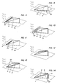
- These vortex generators are characterized by a roof surface and two side surfaces, the side surfaces being flush with the same channel wall and including an arrow angle ⁇ and the longitudinal edges of the roof surface being flush with the longitudinal edges of the side surfaces projecting into the flow channel and below an angle of attack ⁇ to the duct wall.
- the new static mixer which is represented by the 3-dimensional vortex generators, it is possible to achieve extremely short mixing distances in the secondary burners with a low pressure drop.
- the generation of longitudinal vortices without a recirculation area results in a rough mixing of the two streams after a full vortex revolution, while fine mixing due to turbulent flow and molecular diffusion processes already exists after a distance that corresponds to a few channel heights.
- This type of mixture is particularly suitable for mixing the fuel into the combustion air at a relatively low admission pressure and with great dilution.
- a low admission pressure of the fuel is particularly advantageous when using medium and low calorific fuel gases.
- the energy required for mixing is largely drawn from the flow energy of the fluid with the higher volume flow, namely the combustion air.
- the advantage of such vortex generators can be seen in their particular simplicity.
- the element consisting of three walls with flow around it is completely problem-free.
- the roof surface can be joined with the two side surfaces in a variety of ways.
- the element can also be fixed to flat or curved channel walls in the case of weldable materials by simple weld seams. From a fluidic point of view, the element has a very low pressure drop when flowing around and it creates vortices without a dead water area.
- the element due to its generally hollow interior, the element can be cooled in a variety of ways and with various means.
- Fig. 1 50 is a jacketed plenum, which generally receives the combustion air delivered by a compressor, not shown, and supplies it to an annular combustion chamber 1.
- This combustion chamber is constructed in two stages and essentially consists of a pre-combustion chamber 61 and a downstream post-combustion chamber 172, both of which are encased with a combustion chamber wall 63, 63 '.
- an annular dome 55 is placed on the pre-combustion chamber 61, which is located at the head end of the combustion chamber 1 and its combustion chamber through a front plate 54 is limited.
- a burner 110 is arranged in this dome in such a way that the burner outlet is at least approximately flush with the front plate 54.
- the longitudinal axis 51 of the primary burner 110 runs in the longitudinal axis 52 of the pre-combustion chamber 61.
- a plurality, here 30, of such are distributed over the circumference Burners 110 arranged side by side on the annular front plate 54 (Fig. 2A, B).
- the combustion air flows from the plenum 50 into the interior of the dome and acts on the burners via the dome wall perforated at its outer end.
- the fuel is supplied to the burner via a fuel lance 120 which penetrates the plenum and dome walls.
- a number of secondary burners 150 open into the after-combustion chamber. These are also premix burners. Their longitudinal axis 153 extends at an angle of, for example, approximately 30 ° to the longitudinal axis of the pre-combustion chamber 61. In the present example, the cross-sections through which the primary burners 110 and secondary burners 150 flow are dimensioned for approximately half of the total volume flow to be processed.
- a gaseous and / or liquid fuel is injected into the combustion air in the channel 154 of the secondary burner 150.
- the latter also reaches channel 154 via plenum 50, which is not shown. It is guided via vortex generators 9, 9a, of which several are arranged side by side in two channel levels over the circumference.
- the secondary burners 150 are arranged radially on the outside. This radial staggering creates a compact combustion chamber.
- swirl-generating troughs 161 are provided on the combustion chamber wall 63 'of the pre-combustion chamber.
- the transition from the pre-combustion chamber 61 to the post-combustion chamber 172 is provided with a constriction 171 on the combustion chamber wall 63 opposite the confluence of the secondary burners 150.
- the confluence of the secondary burners in the post-combustion chamber 172 is selected such that the mixture has not yet completely burned out in the pre-combustion chamber 61.
- an equal number, here 30 pieces, of primary burners 110 and secondary burners 150 is arranged over the circumference.
- their axes are offset by half a division in the circumferential direction.
- the axes of the primary burner 110 and secondary burner 150 lie on the same radial. It is understood that the number and arrangements shown are not mandatory.
- the mixture was completely burned out in the afterburning chamber 172.
- the hot flue gases then reach the turbine inlet 173 via a transition zone ZT, in which they are accelerated and generally mixed with cooling air.
- premix burners 110 are in each case a so-called double-cone burner, as was already mentioned above and is known for example from EP-B1-0 321 809. It essentially consists of two hollow, conical partial bodies 111, 112, which are nested in the flow direction and thereby enclose the premixing chamber 115.
- the respective central axes 113, 114 of the two partial bodies are offset from one another.
- the adjacent walls of the two partial bodies form in their longitudinal extension tangential slots 119 for the combustion air, which in this way reaches the interior of the burner, ie the premixing chamber 115.
- a first central fuel nozzle 116 for liquid fuel is arranged there. The fuel is injected into the hollow cone at an acute angle.
- the resulting conical fuel profile is enclosed by the combustion air flowing in tangentially.
- the concentration of the fuel is continuously reduced in the axial direction due to the mixing with the combustion air.
- the burner is also operated with gaseous fuel.
- gas inflow openings 117 distributed in the longitudinal direction are provided in the region of the tangential slots 119 in the walls of the two partial bodies. In gas operation, the mixture formation with the combustion air thus already begins in the zone of the inlet slots 119. It goes without saying that mixed operation with both types of fuel is also possible in this way.
- a fuel concentration that is as homogeneous as possible is established over the applied annular cross section.
- a defined dome-shaped recirculation zone 123 is formed, at the tip of which the ignition takes place. The flame itself is stabilized by the recirculation zone in front of the burner without the need for a mechanical flame holder.
- the secondary burner 150 should now be a non-self-operating premix burner. This is understood to mean that permanent ignition must be present for the mixture combustion of the secondary burner. In the present case, this permanent ignition takes place via the flame at the outlet of the pre-combustion chamber 61. When driving with low partial loads, only the primary burners are operated with fuel. The main flow of the secondary burners is then used as dilution air.
- a vortex generator essentially consists of three free-flowing triangular surfaces. These are a roof surface 10 and two side surfaces 11 and 13. In their longitudinal extension, these surfaces run at certain angles in the direction of flow.
- the side walls of the vortex generator which consist of right-angled triangles, are fixed with their long sides on a channel wall 21, preferably gas-tight. They are oriented so that they form a joint on their narrow sides, including an arrow angle ⁇ .
- the joint is designed as a sharp connecting edge 16 and is perpendicular to that channel wall 21 with which the side surfaces are flush.
- the two enclosing the arrow angle ⁇ 4, side surfaces 11, 13 are symmetrical in shape, size and orientation and are arranged on both sides of an axis of symmetry 17. This axis of symmetry 17 is rectified like the channel axis.
- the roof surface 10 lies with a very narrow edge 15 running transversely to the flow through the channel on the same channel wall 21 as the side walls 11, 13. Its longitudinal edges 12, 14 are flush with the longitudinal edges of the side surfaces projecting into the flow channel.
- the roof surface extends at an angle of inclination ⁇ to the channel wall 21. Its longitudinal edges 12, 14 form a tip 18 together with the connecting edge 16.
- the vortex generator can also be provided with a bottom surface with which it is fastened in a suitable manner to the channel wall 21.
- a floor area is not related to the mode of operation of the element.
- the connecting edge 16 of the two side surfaces 11, 13 forms the downstream edge of the vortex generator 9.
- the edge 15 of the roof surface 10 which runs transversely to the flow through the channel is thus the edge which is first acted upon by the channel flow.
- the vortex generator works as follows: When flowing around edges 12 and 14, the main flow is converted into a pair of opposing vortices. Their vortex axes lie in the axis of the main flow. The number of swirls and the location of the vortex breakdown (if the latter is desired at all) are determined by appropriate selection of the angle of attack ⁇ and the arrow angle ⁇ . With increasing angles, the vortex strength or the number of swirls is increased and the location of the vortex bursting moves upstream into the area of the vortex generator themselves. Depending on the application, these two angles ⁇ and ⁇ are determined by the design and by the process itself. Then only the length L of the element and the height h of the connecting edge 16 need to be adjusted (FIG. 7).
- FIG. 5 shows a so-called "half" vortex generator 9a based on a vortex generator according to FIG. 4.
- only one of the two side surfaces, namely surface 11, is provided with the arrow angle ⁇ / 2.
- the other side surface 13 is straight and aligned in the direction of flow.
- only one vortex is generated on the arrowed side. Accordingly, there is no vortex-neutral field downstream of this vortex generator 9a, but a swirl is forced on the flow.
- the sharp connecting edge 16 of the vortex generator 9b is the point which is first acted upon by the channel flow.
- the element is rotated by 180 °.
- the two opposite vortices have changed their sense of rotation.
- the vortex generators 9 are installed in a channel 154.
- the height h of the connecting edge 16 will be coordinated with the channel height H - or the height of the channel part which is assigned to the vortex generator - in such a way that the vortex generated immediately downstream of the vortex generator already reaches such a size that the full channel height H is filled. This leads to a uniform speed distribution in the cross-section applied.
- Another criterion that can influence the ratio h / H to be selected is the pressure drop that occurs when the vortex generator flows around. It goes without saying that the pressure loss coefficient also increases with a larger ratio h / H.
- two vortex generators 9 and 9b are provided in each of the 30 secondary burners in the outlet area. They are distributed over the circumference of the corresponding circular ring segment without a gap.
- the vortex generators could also be strung together on their respective wall segments in the circumferential direction in such a way that gaps between the boundary wall and the side walls are left free.
- the vortex to be generated is decisive here.
- the radially outer vortex generators 9 according to FIG. 4 are arranged, so that their leading edges 15 are first acted upon by the flow.
- the radially inner vortex generators 9b are oriented according to FIG. 6, ie the connecting edges 16 are acted upon first by the flow here.
- the resulting flow field within the circular ring segment is again identified by arrows. It can be seen that the total flow is likewise directed radially inward, but not along the boundary walls 155 on the outside, but in the middle of the segment.
- the vortex generators are therefore mainly used to mix two flows.
- the main flow in the form of combustion air attacks the transverse inlet edges 15 and the connecting edges 16 in the direction of the arrow.
- the secondary flow in the form of a gaseous and / or liquid fuel generally has a substantially smaller mass flow than the main flow, provided that it is not a low-calorie fuel such as for example top gas. In the present case, it is introduced into the main flow upstream of the vortex generators 9 and 9a on the outlet side.
- the fuel is injected into the secondary burners 150 via a central fuel lance 151.
- a cross-jet injection of the fuel is shown, the fuel pulse having to be approximately twice that of the main flow.
- a longitudinal injection in the direction of flow could just as well be provided. In this case, the injection pulse corresponds approximately to that of the main flow pulse.
- the injected fuel is dragged along by the vortices and mixed with the main flow. It follows the helical course of the vertebrae and is evenly finely distributed in the chamber downstream of the vertebrae. This reduces the risk of impinging jets on the opposite wall and the formation of so-called "hot spots" - in the case of the radial injection of fuel into an undisturbed flow mentioned at the beginning.
- the fuel injection can be kept flexible and adapted to other boundary conditions. In this way, the same injection pulse can be maintained throughout the load range. Since the mixing is determined by the geometry of the vortex generators and not by the machine load, in this case the gas turbine output, the burner configured in this way works optimally even under partial load conditions.
- the combustion process will by adjusting the ignition delay time of the fuel and the mixing time of the vortices, which ensures a minimization of emissions.
- the fuel can also be supplied to the channel 154 in another way. 1, it is possible to introduce the fuel directly into the area of the vortex generators via gas supply channels 152.
- FIGS. 8 to 14 show such possible forms of introducing the fuel into the combustion air with regard to the secondary burners. These variants can be combined with each other and with a central fuel injection in a variety of ways.
- the fuel in addition to wall bores 22a downstream of the vortex generators, the fuel is injected via wall bores 22c which are located directly next to the side walls 11, 13 and in their longitudinal extent in the same wall 21 on which the vortex generators are arranged are. Introducing the fuel through the wall bores 22c gives the generated vortices an additional impulse, which extends its life.
- the fuel is injected on the one hand via a slot 22e or via wall bores 22f, which are located directly in front of the edge 15 of the roof surface 10 running transversely to the flow channel and in its longitudinal extent in the same wall 21 on which the eddies are located Generators are arranged.
- the geometry of the wall bores 22f or of the slot 22e is selected such that the fuel is injected into the main flow at a specific injection angle and the subsequent vortex generator flows around as a protective film against the hot main flow.
- the secondary flow is first introduced through the channel wall 21 into the hollow interior of the vortex generator by means not shown. This creates an internal cooling facility for the vortex generators.
- the fuel is injected via wall bores 22g, which are located within the roof area 10 directly behind the edge 15 running transversely to the flowed channel and in its longitudinal extent.
- the vortex generator is cooled more externally than internally.
- the secondary flow emerging forms a protective layer shielding the hot main flow when it flows around the roof surface 10.
- the fuel is injected via wall bores 22h, which are staggered within the roof surface 10 along the line of symmetry 17.
- the channel walls are particularly well protected from the hot main flow, since the fuel is first introduced on the outer circumference of the vortex.
- the fuel is injected via wall bores 22j, which are located in the longitudinal edges 12, 14 of the roof surface 10.
- This solution ensures good cooling of the vortex generators, since the fuel escapes from its extremities and thus completely flushes the inner walls of the element.
- the secondary flow is fed directly into the resulting vortex, which leads to defined flow conditions.
- the injection takes place via wall bores 22d, which are located in the side surfaces 11 and 13 on the one hand in the area the longitudinal edges 12 and 14 and on the other hand in the area of the connecting edge 16.
- This variant is similar in effect to that from the bores 22a in FIG. 8 and from the bores 22j in FIG. 13.
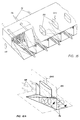
- Fig. 15 shows a partial perspective view of the meeting of the secondary burners and the pre-combustion chamber.
- the vortex generators provided here in the outlet area of the secondary burners correspond to those according to FIG. 2A.
- the radially inner "half" vortex generators 9a shown are flowed to first with the connecting edge 16, which is here in the same radial as the segment boundary wall 155; the radially outer "half" vortex generators 9a are first flowed over with the edge 15 running in the circumferential direction.
- vortex-generating troughs 161 are provided at the outlet of the pre-combustion chamber 61 in the region of the confluence of the secondary burners 150 on the combustion chamber wall 63 'of the pre-combustion chamber and are constructed similarly to the vortex generators described so far. In contrast to these, the two side surfaces and the roof surface do not form a specific tip. As shown in FIG. 1, the radially outer flow of the pre-combustion chamber is swirled radially outward by these stepped troughs and impinges on the mixture of secondary burners flowing inwards.
- the transition from the pre-combustion chamber 61 to the afterburning chamber 62 is provided with a constriction 171 on the combustion chamber wall 63 opposite the troughs 161, so as not to disturb the surface conditions.
- Fig. 16 shows a partial perspective view of the entrance of the secondary burner, again in this first level half vortex generators 9a are arranged according to FIG. 5, but in a different arrangement than that at the secondary burner outlet.
- a central fuel lance 151 for oil and gas feed pipe 156 to the vortex generators are provided for the individual burners.
- 16A which shows a detailed view of FIG. 16, shows the eddy formation on both sides of the radially running segment boundary wall 155; the fact that the half vortex generators arranged next to one another in the circumferential direction alternately act upon the edge 15 and the edge 16 by the air first, creates a total vortex in the same direction in the counterclockwise direction.
- the vortex generators in the secondary burners can be designed so that recirculation zones downstream are largely avoided. As a result, the residence time of the fuel particles in the hot zones is very short, which has a favorable effect on the minimal formation of NOx.
- the vortex generators can also be designed and staggered in the depth of the channel 154 in such a way that a defined backflow zone 170 arises at the outlet of the secondary burners, which stabilizes the flame in an aerodynamic manner, i.e. without mechanical flame holder.
- the mixture leaves the secondary burner 150 with a vortex and enters the flame from the pre-combustion chamber 61.
- the mixture leaves the secondary burner 150 with a vortex and enters the flame from the pre-combustion chamber 61.
- the collision of the two eddy currents there is intimate mixing over the shortest distance and a renewed vortex burst, which leads to the backflow zone 170 already mentioned.
- the intensive mixing results in a good temperature profile over the cross-section through which the air flows and also reduces the possibility of thermoacoustic instability. Due to their presence alone, the vortex generators act as a damping measure against thermoacoustic vibrations.
- the partial load operation of combustion chambers can be easily implemented by means of a graduated fuel supply to the individual modules. If only the primary burners are operated with a premix flame, the main flow of the secondary burners is used as dilution air. This strongly swirled main flow mixes very quickly with the hot gases emerging from the primary stage at the outlet of the secondary burners. A uniform temperature profile is thus generated downstream.
- fuel is gradually injected into the secondary burner and mixed intensively into the combustion air before ignition. So these secondary burners always work in premix mode; they are ignited and stabilized from the primary burners.
- the burner aerodynamics consist of two radially graded vortex images.
- the radially outer vortices depend on the number and geometry of the vortex generators 9.
- the radially inner vortex structure emanating from the double-cone burner can be influenced by adapting certain geometric parameters on the double-cone burner.
- the quantity distribution between the primary burner and the secondary burner can be carried out as required by appropriately coordinating the areas through which the flow flows, taking into account the pressure losses. Because the vortex generators have a relatively low pressure drop, the secondary burners can flow through at a higher speed than the primary burner. A higher speed at the outlet of the secondary burner has a favorable effect on the flame's kickback.
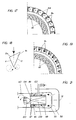
- FIG. 17 An annular combustion chamber is proposed in FIG. 17 , in which the radially stepped vortex images described above are precisely defined.
- the radially inner large-scale vortex and the radially outer vortex have the opposite direction of rotation.
- a number of vortex generators 9a according to FIG. 5 are grouped around the double-cone burner 101. These are so-called half vortex generators, in which only one of the two side surfaces of the vortex generator 9a is provided with the arrow angle ⁇ / 2. The other side surface is straight and aligned in the burner axis. In contrast to the symmetrical vortex generator, only one vortex is generated on the arrowed side.
- FIGS. 18 and 19 show a top view of an embodiment variant of a vortex generator 9c and a front view of its arrangement in an annular channel.
- the two side surfaces 11 and 13 enclosing the arrow angle ⁇ have a different length.
- the vortex generator then naturally has a different angle of attack stell across its width.
- Such a variant has the effect that vertebrae with different Strength are generated. For example, this can act on a swirl adhering to the main flow. Or, due to the different vortices, a swirl is forced on the originally swirl-free main flow downstream of the vortex generators.
- Such configurations are well suited as an independent, compact burner unit.
- the swirl imposed on the main flow can be exploited to improve the cross-ignition behavior of the burner configuration, e.g. at partial load.
- 173 (as in FIG. 1) denotes the first turbine guide vane row.
- the effect of the new measure is as follows: On the occasion of the pre-combustion, as a result of the split in half between the primary burner and secondary burner, only half of the total volume flow as a result of the temperature increase ⁇ T 1C produces nitrogen. This half volume flow has only a short dwell time in the pre-combustion chamber 61 until it is mixed with the mixture from the secondary burners, which has a favorable effect on the NO x production.
- the mixing temperature must not drop below the compression ignition temperature T SI .
- the invention is not limited to the use of primary burners of the double-cone type shown. Rather, it can be used in all combustion chamber zones in which flame stabilization is generated by a prevailing air velocity field.
- FIG. 21 As another example of this, reference is made to the burner shown in FIG. 21.
- all functionally identical elements are provided with the same reference numerals as in the burner according to FIGS. 1-3B. This is despite a different structure, which applies in particular to the tangential inflow gaps 119 which run here cylindrically.
- the area of the premixing chamber 115 which flows through in the direction of the burner outlet is formed in this burner by a centrally arranged insert 130 in the form of a straight circular cone, the cone tip being in the region of the front plate plane. It goes without saying that the lateral surface of this cone can also be curved. Incidentally, this also applies to the course of the partial surfaces 111, 112 in the burners shown in FIGS. 1-3B.
Landscapes
- Engineering & Computer Science (AREA)
- Mechanical Engineering (AREA)
- General Engineering & Computer Science (AREA)
- Chemical & Material Sciences (AREA)
- Combustion & Propulsion (AREA)
- Physics & Mathematics (AREA)
- Fluid Mechanics (AREA)
- Gas Burners (AREA)
Applications Claiming Priority (2)
| Application Number | Priority Date | Filing Date | Title |
|---|---|---|---|
| DE19510744A DE19510744A1 (de) | 1995-03-24 | 1995-03-24 | Brennkammer mit Zweistufenverbrennung |
| DE19510744 | 1995-03-24 |
Publications (1)
| Publication Number | Publication Date |
|---|---|
| EP0733861A2 true EP0733861A2 (fr) | 1996-09-25 |
Family
ID=7757580
Family Applications (1)
| Application Number | Title | Priority Date | Filing Date |
|---|---|---|---|
| EP96810132A Withdrawn EP0733861A2 (fr) | 1995-03-24 | 1996-03-06 | Chambre de combustion à combustion étagée |
Country Status (5)
| Country | Link |
|---|---|
| US (1) | US5829967A (fr) |
| EP (1) | EP0733861A2 (fr) |
| JP (1) | JPH08270948A (fr) |
| CN (1) | CN1142036A (fr) |
| DE (1) | DE19510744A1 (fr) |
Cited By (5)
| Publication number | Priority date | Publication date | Assignee | Title |
|---|---|---|---|---|
| EP1890083A1 (fr) * | 2006-08-16 | 2008-02-20 | Siemens Aktiengesellschaft | Injecteur de carburant pour une turbine à gaz |
| EP1975506A1 (fr) * | 2007-03-30 | 2008-10-01 | Siemens Aktiengesellschaft | Pré-chambre de combustion |
| EP2112433A1 (fr) * | 2008-04-23 | 2009-10-28 | Siemens Aktiengesellschaft | Chambre de mélange |
| EP2199674A1 (fr) * | 2008-12-19 | 2010-06-23 | ALSTOM Technology Ltd | Brûleur d'une turbine à gaz |
| EP3023698A1 (fr) * | 2014-11-19 | 2016-05-25 | Rolls-Royce Deutschland Ltd & Co KG | Dispositif de determination d'un rapport de gradation, une turbine a gaz ou moteur d'aeronef comprenant un tel dispositif et son utilisation |
Families Citing this family (50)
| Publication number | Priority date | Publication date | Assignee | Title |
|---|---|---|---|---|
| DE19542644B4 (de) * | 1995-11-17 | 2008-12-11 | Alstom | Vormischverbrennung |
| DE19728375A1 (de) * | 1997-07-03 | 1999-01-07 | Bmw Rolls Royce Gmbh | Betriebsverfahren für eine axial gestufte Brennkammer einer Fluggasturbine |
| DE19730617A1 (de) * | 1997-07-17 | 1999-01-21 | Abb Research Ltd | Druckzerstäuberdüse |
| DE10108560A1 (de) * | 2001-02-22 | 2002-09-05 | Alstom Switzerland Ltd | Verfahren zum Betrieb einer Ringbrennkammer sowie eine diesbezügliche Ringbrennkammer |
| DE10128063A1 (de) * | 2001-06-09 | 2003-01-23 | Alstom Switzerland Ltd | Brennersystem |
| DE50212743D1 (de) * | 2002-01-14 | 2008-10-16 | Alstom Technology Ltd | Brenneranordnung für die ringförmige brennkammer einer gasturbine |
| DE10205428A1 (de) * | 2002-02-09 | 2003-09-11 | Alstom Switzerland Ltd | Vormischbrenner mit erhöhter Flammenstabilität |
| DE10330023A1 (de) * | 2002-07-20 | 2004-02-05 | Alstom (Switzerland) Ltd. | Wirbelgenerator mit kontrollierter Nachlaufströmung |
| JP4472932B2 (ja) * | 2003-02-07 | 2010-06-02 | いすゞ自動車株式会社 | エンジンの燃焼制御装置 |
| CA2543470A1 (fr) * | 2003-10-21 | 2005-05-12 | Petroleum Analyzer Company, Lp | Appareil de combustion ameliore et procedes de fabrication et d'utilisation correspondants |
| EP1568942A1 (fr) * | 2004-02-24 | 2005-08-31 | Siemens Aktiengesellschaft | Brûleur à prémélange et procédé pour brûler un gaz pauvre |
| EP2041494B8 (fr) * | 2005-12-14 | 2015-05-27 | Industrial Turbine Company (UK) Limited | Injecteurs de prémélange de turbine à gaz |
| US8015814B2 (en) * | 2006-10-24 | 2011-09-13 | Caterpillar Inc. | Turbine engine having folded annular jet combustor |
| WO2009019113A2 (fr) * | 2007-08-07 | 2009-02-12 | Alstom Technology Ltd | Brûleur pour une chambre de combustion d'un turbogroupe |
| JP5173393B2 (ja) | 2007-12-21 | 2013-04-03 | 三菱重工業株式会社 | ガスタービン燃焼器 |
| DE102008050599B3 (de) * | 2008-10-09 | 2010-07-29 | Uhde Gmbh | Vorrichtung und Verfahren zur Verteilung von Primärluft in Koksöfen |
| JP5562548B2 (ja) * | 2008-10-31 | 2014-07-30 | 光洋サーモシステム株式会社 | 熱処理装置 |
| US8650881B2 (en) * | 2009-06-30 | 2014-02-18 | General Electric Company | Methods and apparatus for combustor fuel circuit for ultra low calorific fuels |
| US8863525B2 (en) | 2011-01-03 | 2014-10-21 | General Electric Company | Combustor with fuel staggering for flame holding mitigation |
| DE102011018846A1 (de) | 2011-01-19 | 2012-07-19 | GETAS GESELLSCHAFT FüR THERMODYNAMISCHE ANTRIEBSSYSTEME MBH | Axialkolbenmotor sowie Verfahren zum Betrieb eines Axialkolbenmotors |
| US8601820B2 (en) | 2011-06-06 | 2013-12-10 | General Electric Company | Integrated late lean injection on a combustion liner and late lean injection sleeve assembly |
| US9010120B2 (en) | 2011-08-05 | 2015-04-21 | General Electric Company | Assemblies and apparatus related to integrating late lean injection into combustion turbine engines |
| US8407892B2 (en) | 2011-08-05 | 2013-04-02 | General Electric Company | Methods relating to integrating late lean injection into combustion turbine engines |
| US8522553B2 (en) * | 2011-09-14 | 2013-09-03 | General Electric Company | System and method for conditioning a working fluid in a combustor |
| EP2602549A1 (fr) * | 2011-12-09 | 2013-06-12 | Siemens Aktiengesellschaft | Chambre de combustion pour une turbine à gaz, turbine à gaz ainsi que procédé |
| US9140455B2 (en) | 2012-01-04 | 2015-09-22 | General Electric Company | Flowsleeve of a turbomachine component |
| US9310078B2 (en) | 2012-10-31 | 2016-04-12 | General Electric Company | Fuel injection assemblies in combustion turbine engines |
| US20140123653A1 (en) * | 2012-11-08 | 2014-05-08 | General Electric Company | Enhancement for fuel injector |
| GB201315871D0 (en) * | 2013-09-06 | 2013-10-23 | Rolls Royce Plc | A combustion chamber arrangement |
| US20150159878A1 (en) * | 2013-12-11 | 2015-06-11 | Kai-Uwe Schildmacher | Combustion system for a gas turbine engine |
| US9683744B2 (en) | 2014-02-28 | 2017-06-20 | Pratt & Whitney Canada Corp. | Combustion system for a gas turbine engine and method of operating same |
| JP6602004B2 (ja) * | 2014-09-29 | 2019-11-06 | 川崎重工業株式会社 | 燃料噴射器及びガスタービン |
| US10465909B2 (en) | 2016-11-04 | 2019-11-05 | General Electric Company | Mini mixing fuel nozzle assembly with mixing sleeve |
| US10393382B2 (en) | 2016-11-04 | 2019-08-27 | General Electric Company | Multi-point injection mini mixing fuel nozzle assembly |
| US10295190B2 (en) | 2016-11-04 | 2019-05-21 | General Electric Company | Centerbody injector mini mixer fuel nozzle assembly |
| US10352569B2 (en) | 2016-11-04 | 2019-07-16 | General Electric Company | Multi-point centerbody injector mini mixing fuel nozzle assembly |
| US10724740B2 (en) | 2016-11-04 | 2020-07-28 | General Electric Company | Fuel nozzle assembly with impingement purge |
| US10634353B2 (en) | 2017-01-12 | 2020-04-28 | General Electric Company | Fuel nozzle assembly with micro channel cooling |
| EP3354849A1 (fr) * | 2017-01-31 | 2018-08-01 | Siemens Aktiengesellschaft | Paroi pour composant à gaz chaud et composant à gaz chaud associé pour turbine à gaz |
| JP6769370B2 (ja) | 2017-03-27 | 2020-10-14 | 株式会社Ihi | 燃焼装置及びガスタービン |
| US10890329B2 (en) | 2018-03-01 | 2021-01-12 | General Electric Company | Fuel injector assembly for gas turbine engine |
| CN110748919B (zh) * | 2018-07-23 | 2024-04-12 | 中国联合重型燃气轮机技术有限公司 | 燃料喷嘴 |
| CN110748920B (zh) * | 2018-07-23 | 2024-02-09 | 中国联合重型燃气轮机技术有限公司 | 轴向分级燃烧器 |
| US10935245B2 (en) | 2018-11-20 | 2021-03-02 | General Electric Company | Annular concentric fuel nozzle assembly with annular depression and radial inlet ports |
| US11073114B2 (en) | 2018-12-12 | 2021-07-27 | General Electric Company | Fuel injector assembly for a heat engine |
| US11286884B2 (en) | 2018-12-12 | 2022-03-29 | General Electric Company | Combustion section and fuel injector assembly for a heat engine |
| US11156360B2 (en) | 2019-02-18 | 2021-10-26 | General Electric Company | Fuel nozzle assembly |
| US11454396B1 (en) * | 2021-06-07 | 2022-09-27 | General Electric Company | Fuel injector and pre-mixer system for a burner array |
| JP2023148761A (ja) * | 2022-03-30 | 2023-10-13 | 三菱重工業株式会社 | 燃焼器及びガスタービン |
| CN116293800A (zh) * | 2023-02-24 | 2023-06-23 | 北京航空航天大学 | 燃烧室微混头部、燃气轮机燃烧室及燃气轮机 |
Family Cites Families (13)
| Publication number | Priority date | Publication date | Assignee | Title |
|---|---|---|---|---|
| DE2629761A1 (de) * | 1976-07-02 | 1978-01-05 | Volkswagenwerk Ag | Brennkammer fuer gasturbinen |
| US4141213A (en) * | 1977-06-23 | 1979-02-27 | General Motors Corporation | Pilot flame tube |
| CH674561A5 (fr) * | 1987-12-21 | 1990-06-15 | Bbc Brown Boveri & Cie | |
| JP2852110B2 (ja) * | 1990-08-20 | 1999-01-27 | 株式会社日立製作所 | 燃焼装置及びガスタービン装置 |
| EP0576697B1 (fr) * | 1992-06-29 | 1997-08-27 | Abb Research Ltd. | Chambre de combustion pour turbine à gaz |
| DE4242003A1 (de) * | 1992-12-12 | 1994-06-16 | Abb Research Ltd | Prozesswärmeerzeuger |
| DE59401295D1 (de) * | 1993-04-08 | 1997-01-30 | Abb Management Ag | Mischkammer |
| EP0623786B1 (fr) * | 1993-04-08 | 1997-05-21 | Asea Brown Boveri Ag | Chambre de combustion |
| CH687269A5 (de) * | 1993-04-08 | 1996-10-31 | Abb Management Ag | Gasturbogruppe. |
| CH687831A5 (de) * | 1993-04-08 | 1997-02-28 | Asea Brown Boveri | Vormischbrenner. |
| DE59401018D1 (de) * | 1993-04-08 | 1996-12-19 | Abb Management Ag | Mischkammer |
| EP0626543A1 (fr) * | 1993-05-24 | 1994-11-30 | Westinghouse Electric Corporation | Chambre de combustion à géométrie fixe avec basses émissions pour une turbine à gaz |
| DE4411622A1 (de) * | 1994-04-02 | 1995-10-05 | Abb Management Ag | Vormischbrenner |
-
1995
- 1995-03-24 DE DE19510744A patent/DE19510744A1/de not_active Withdrawn
-
1996
- 1996-02-05 US US08/596,768 patent/US5829967A/en not_active Expired - Fee Related
- 1996-03-06 EP EP96810132A patent/EP0733861A2/fr not_active Withdrawn
- 1996-03-22 CN CN96107375A patent/CN1142036A/zh active Pending
- 1996-03-25 JP JP8068296A patent/JPH08270948A/ja active Pending
Cited By (9)
| Publication number | Priority date | Publication date | Assignee | Title |
|---|---|---|---|---|
| EP1890083A1 (fr) * | 2006-08-16 | 2008-02-20 | Siemens Aktiengesellschaft | Injecteur de carburant pour une turbine à gaz |
| EP1975506A1 (fr) * | 2007-03-30 | 2008-10-01 | Siemens Aktiengesellschaft | Pré-chambre de combustion |
| WO2008119737A1 (fr) * | 2007-03-30 | 2008-10-09 | Siemens Aktiengesellschaft | Préchambre de combustion |
| EP2112433A1 (fr) * | 2008-04-23 | 2009-10-28 | Siemens Aktiengesellschaft | Chambre de mélange |
| US8424310B2 (en) | 2008-04-23 | 2013-04-23 | Siemens Aktiengesellschaft | Mixing chamber |
| EP2199674A1 (fr) * | 2008-12-19 | 2010-06-23 | ALSTOM Technology Ltd | Brûleur d'une turbine à gaz |
| US8938968B2 (en) | 2008-12-19 | 2015-01-27 | Alstom Technology Ltd. | Burner of a gas turbine |
| EP3023698A1 (fr) * | 2014-11-19 | 2016-05-25 | Rolls-Royce Deutschland Ltd & Co KG | Dispositif de determination d'un rapport de gradation, une turbine a gaz ou moteur d'aeronef comprenant un tel dispositif et son utilisation |
| US10156361B2 (en) | 2014-11-19 | 2018-12-18 | Rolls-Royce Deutschland Ltd & Co Kg | Device for determining a fuel split, as gas turbine or an aircraft engine comprising such a device and application of the same |
Also Published As
| Publication number | Publication date |
|---|---|
| DE19510744A1 (de) | 1996-09-26 |
| US5829967A (en) | 1998-11-03 |
| JPH08270948A (ja) | 1996-10-18 |
| CN1142036A (zh) | 1997-02-05 |
Similar Documents
| Publication | Publication Date | Title |
|---|---|---|
| EP0733861A2 (fr) | Chambre de combustion à combustion étagée | |
| EP0675322B1 (fr) | Brûleur à prémélange | |
| EP0623786B1 (fr) | Chambre de combustion | |
| DE4426351B4 (de) | Brennkammer für eine Gasturbine | |
| DE60007946T2 (de) | Eine Brennkammer | |
| EP0619457B1 (fr) | Brûleur à prémélange | |
| DE69804022T2 (de) | Pilotbrennerkegel für brennkammer mit niedrigem nox ausstoss | |
| DE69205855T2 (de) | Luft-/Kraftstoff-Mischer für eine Gasturbinenbrennkammer. | |
| DE60128513T2 (de) | Verfahren und Vorrichtung zur Verminderung der Emissionen in einer Brennkammer mit einer Wirbelmischvorrichtung | |
| DE69719688T2 (de) | Gasturbinenbrenner und Betriebsverfahren dafür | |
| DE2338673C2 (de) | Nachbrenneranordnung für ein Gasturbinenstrahltriebwerk | |
| EP0619456B1 (fr) | Système d'alimentation en carburant pour chambre de combustion | |
| DE69617290T2 (de) | Verbrennungsgerät für Gasturbinenmotor | |
| DE4411623A1 (de) | Vormischbrenner | |
| EP0620403B1 (fr) | Dispositif de mélange et de stabilisation de la flamme dans une chambre de combustion avec mélange préalable du combustible. | |
| DE10064259B4 (de) | Brenner mit hoher Flammenstabilität | |
| EP2156095B1 (fr) | Stabilisation sans tourbillonner de la flamme d'un brûleur à prémélange | |
| DE4417538A1 (de) | Brennkammer mit Selbstzündung | |
| DE10050248A1 (de) | Brenner | |
| EP0718561B1 (fr) | Brûleur | |
| CH680084A5 (fr) | ||
| EP0851172B1 (fr) | Brûleur et méthode pour la mise en oeuvre d'une chambre de combustion avec un combustible liquide et/ou gazeux | |
| EP0394800B1 (fr) | Brûleur à mélange préalable pour la génération de gaz chaud | |
| EP0742411B1 (fr) | Alimentation en air pour une chambre de combustion à prémélange | |
| EP0730121A2 (fr) | Brûleur à prémélange |
Legal Events
| Date | Code | Title | Description |
|---|---|---|---|
| PUAI | Public reference made under article 153(3) epc to a published international application that has entered the european phase |
Free format text: ORIGINAL CODE: 0009012 |
|
| AK | Designated contracting states |
Kind code of ref document: A2 Designated state(s): DE FR GB |
|
| RAP1 | Party data changed (applicant data changed or rights of an application transferred) |
Owner name: ASEA BROWN BOVERI AG |
|
| STAA | Information on the status of an ep patent application or granted ep patent |
Free format text: STATUS: THE APPLICATION HAS BEEN WITHDRAWN |
|
| 18W | Application withdrawn |
Withdrawal date: 19980220 |