EP0730121A2 - Brûleur à prémélange - Google Patents
Brûleur à prémélange Download PDFInfo
- Publication number
- EP0730121A2 EP0730121A2 EP96810089A EP96810089A EP0730121A2 EP 0730121 A2 EP0730121 A2 EP 0730121A2 EP 96810089 A EP96810089 A EP 96810089A EP 96810089 A EP96810089 A EP 96810089A EP 0730121 A2 EP0730121 A2 EP 0730121A2
- Authority
- EP
- European Patent Office
- Prior art keywords
- channel
- fuel
- premix burner
- combustion chamber
- burner
- Prior art date
- Legal status (The legal status is an assumption and is not a legal conclusion. Google has not performed a legal analysis and makes no representation as to the accuracy of the status listed.)
- Withdrawn
Links
Images

Classifications
-
- F—MECHANICAL ENGINEERING; LIGHTING; HEATING; WEAPONS; BLASTING
- F23—COMBUSTION APPARATUS; COMBUSTION PROCESSES
- F23C—METHODS OR APPARATUS FOR COMBUSTION USING FLUID FUEL OR SOLID FUEL SUSPENDED IN A CARRIER GAS OR AIR
- F23C7/00—Combustion apparatus characterised by arrangements for air supply
- F23C7/02—Disposition of air supply not passing through burner
- F23C7/06—Disposition of air supply not passing through burner for heating the incoming air
-
- F—MECHANICAL ENGINEERING; LIGHTING; HEATING; WEAPONS; BLASTING
- F23—COMBUSTION APPARATUS; COMBUSTION PROCESSES
- F23D—BURNERS
- F23D17/00—Burners for combustion conjointly or alternatively of gaseous or liquid or pulverulent fuel
- F23D17/002—Burners for combustion conjointly or alternatively of gaseous or liquid or pulverulent fuel gaseous or liquid fuel
-
- F—MECHANICAL ENGINEERING; LIGHTING; HEATING; WEAPONS; BLASTING
- F23—COMBUSTION APPARATUS; COMBUSTION PROCESSES
- F23M—CASINGS, LININGS, WALLS OR DOORS SPECIALLY ADAPTED FOR COMBUSTION CHAMBERS, e.g. FIREBRIDGES; DEVICES FOR DEFLECTING AIR, FLAMES OR COMBUSTION PRODUCTS IN COMBUSTION CHAMBERS; SAFETY ARRANGEMENTS SPECIALLY ADAPTED FOR COMBUSTION APPARATUS; DETAILS OF COMBUSTION CHAMBERS, NOT OTHERWISE PROVIDED FOR
- F23M9/00—Baffles or deflectors for air or combustion products; Flame shields
- F23M9/02—Baffles or deflectors for air or combustion products; Flame shields in air inlets
Definitions
- the present invention relates to a premix burner according to the preamble of claim 1. It also relates to a method for operating such a premix burner.
- the invention seeks to remedy this.
- the invention is based on the object of proposing a configuration for a premix burner and a method of the type mentioned at the outset, which can produce the same depth of pollutant emissions when operated with both liquid and gaseous fuels. Furthermore, it is an object of the invention to maximize the operational reliability of the premix burner.
- the main advantage of the invention can be seen in the fact that the burner can be operated in premix mode with both liquid and gaseous fuels without changing its structure under extremely low emission values. It is therefore possible to change the fuel type as required during operation without having to intervene in the configuration of the burner.
- Another advantage of the invention is that the cooling of the thermally highly loaded front wall of the burner, hereinafter referred to as the burner front, and its surroundings is accomplished by a cooling air stream flowing along the loaded walls, such that even in the event of a flashback of the flame inside the flame the burner cannot be destroyed.
- the burner has a simple geometric shape, and the length of the evaporation and mixing section can be selected accordingly. After the fuel has been added, there are no internals in the flow field, which means that the flow can be optimally guided. Because the evaporation and mixing section can be freely selected, it can also be provided with a radial deflection which takes the mixing zone away from the direct flame radiation.
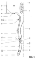
- the figure shows a rotationally symmetrical premix burner 1, as can be seen from the central axis 14.
- the premix burner 1 can, however, also consist of a single tube, or a plurality of tubes can be arranged in a ring around the central axis 14.
- This premix burner 1 is characterized, inter alia, in the area of the burner front 9 by an inflow channel 8 running radially and in the circumferential direction. Cooling air 7 flows through this inflow duct 8 and continuously cools said burner front 9. The cooling air flow is then continued by a deflection along the outer shell of the premix burner 1. After the cooling process has ended, the cooling air mentioned is preferably introduced into the premix burner 1 at a suitable point.
- the cooling provided here is in itself a convective cooling system, the tube guide of the premix burner 1 being readily perforated in the circumferential direction and axially, with the result that effusion cooling or. film cooling comes into play.
- swirl bodies 200 hereinafter referred to as vortex generators, are provided, which impose a swirl on the incoming combustion air 2.
- This combustion air 2 can be fresh air or a mixture formed with recirculated flue gas, both the fresh air and the mixture optionally being enriched with a fuel.
- the combustion air 2 can also be pretreated, depending on the type of operation.
- the actual fuel injection into the premix burner 1 takes place downstream of the vortex generators 200 mentioned.
- a liquid fuel 12a at least one fuel nozzle 12, which is preferably designed as an atomizing nozzle, is arranged in the throughflow channel.
- a further swirl generator 4 arranged, which is flowed through axially, radially or at a certain angle compared to the fuel injection immediately downstream.
- the liquid fuel 12a provided by the fuel nozzle 12 is continuously driven in by the combustion air flow directed due to the design of the swirl generator 4, in such a way that fine atomization of the liquid fuel 12a with droplet sizes ⁇ 20 ⁇ m is produced.
- the swirl generator 4 mentioned wherein several can also be arranged on the inner outer wall of the flow cross-section, can have the shape of a vane grille over the circumference or a correspondingly modified shape of the burner recognized in the foregoing according to EP-0 321 809.
- these swirl generators 4 can be constructed using the technique of vortex generators 200.
- the vortex generators 200 arranged upstream at the beginning of the premix burner 1 can be dispensed with under certain circumstances, it being noted that in normal operation they improve the subsequent process by accelerating the combustion air 2 there.
- These vortex generators 200 are placed differently within the inflow zone 3 around the inner and outer channel wall 17 of the flow cross section.
- a sufficiently long evaporation section 6 should be provided so that the gasification of the liquid fuel 12a is completed before reaching the burner front 9.
- the cross-sectional area of the premix burner is preferably kept constant from the swirl body 4 to the end of the hub body, that is to say in the area of the burner front 9, after which a vortex burst is achieved by a diffuser-like expansion and additionally by a sudden expansion to the cross-section 10 of the combustion chamber 16.
- the backflow zone 11 that results from this enables the premix burner 1 to be operated even under very low fuel conditions.
- the premix burner 1 is supplemented with a gaseous fuel 5a in the circumferential direction and downstream of the swirl generator 4, which is now arranged around the inner wall of the flow cross-section, with a series of injection lances 5, preferably with a corresponding fuel injection for each swirl generator 4, this by the desired fuel ratio to each Achieve longitudinal vertebrae better.
- additional fuel nozzles 15 for a liquid and / or gaseous fuel 12a, 5a can be provided at the end of the hub body.
- the premix burner 1 can also be operated in dual mode.
- the cross-sectional guide of the premix burner 1 Downstream of the main fuel injectors 12a, 5a, the cross-sectional guide of the premix burner 1 has a radial deflection in the sense of a bulge 13, which prevents the flame radiation from acting on the fuel spray and igniting it. Since the fuel nozzle 12 is operated in the arrangement described with a very high mass flow ratio, the required degree of gasification of the liquid fuel 12a can be easily achieved.
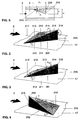
- a vortex generator 200, 201, 202 essentially consists of three freely flowing triangular surfaces. These are a roof surface 210 and two side surfaces 211 and 213. In their longitudinal extent, these surfaces run at certain angles in the direction of flow.
- the side walls of the vortex generators 200, 201, 202, which preferably consist of right-angled triangles, are fixed with their long sides on the channel wall 17 already mentioned, preferably gas-tight. They are oriented so that they form a joint on their narrow sides, including an arrow angle ⁇ .
- the joint is designed as a sharp connecting edge 216 and is perpendicular to each channel wall 17 with which the side surfaces are flush.
- the two side surfaces 211, 213 including the arrow angle ⁇ are symmetrical in shape, size and orientation in FIG. 4, they are arranged on both sides of an axis of symmetry 217 which is oriented in the same direction as the channel axis.
- the roof surface 210 lies with a very narrow edge 215 running transversely to the channel through which it flows and on the same channel wall 17 as the side surfaces 211,. 213.
- Their longitudinal edges 212, 214 are flush with the longitudinal edges of the side surfaces 211, 213 projecting into the flow channel.
- the roof surface 210 extends at an angle of inclination ⁇ to the channel wall 17, the longitudinal edges 212, 214 of which, together with the connecting edge 216, form a point 218.
- the vortex generator 200, 201, 202 can also be provided with a bottom surface with which it is fastened in a suitable manner to the channel wall 17. Such a floor area is, however, unrelated to the mode of operation of the element.
- the mode of operation of the vortex generator 200, 201, 202 is as follows: When flowing around the edges 212 and 214, the main flow 2 is converted into a pair of opposing vortices, as is schematically outlined in the figures.
- the vortex axes lie in the axis of this main flow.
- the vortex strength or the number of swirls is increased, and the location of the vortex bursting shifts upstream into the region of the vortex generator 200, 201, 202 itself.
- these two angles ⁇ and ⁇ are due to structural conditions and determined by the process itself.
- These vortex generators only have to be adjusted with regard to Length and height, as will be detailed below in FIG. 5.
- the connecting edge 216 of the two side surfaces 211, 213 forms the downstream edge of the vortex generator 200.
- the edge 215 of the roof surface 210 running transversely to the flow through the channel is thus the edge which is first acted upon by the channel flow.
- FIG. 3 shows a so-called half "vortex generator” based on a vortex generator according to FIG. 2.
- the vortex generator 201 shown here only one of the two side surfaces is provided with the arrow angle ⁇ / 2.
- the other side surface is straight and oriented in the direction of flow.
- only one vortex is generated on the arrowed side, as is shown in the figure. Accordingly, there is no vortex-neutral field downstream of this vortex generator, but a swirl is forced on the flow.
- FIG. 4 differs from FIG. 2 in that the sharp connecting edge 216 of the vortex generator 202 is the point which is first acted upon by the channel flow. The element is therefore rotated by 180 °. As can be seen from the illustration, the two opposite vortices have changed their sense of rotation.
- FIG. 5 shows the basic geometry of a vortex generator 200 installed in a channel 3.
- the height h of the connecting edge 216 will be coordinated with the channel height H, or the height of the channel part which is assigned to the vortex generator that the vortex generated immediately downstream of the vortex generator 200 already reaches such a size that the full channel height H is filled. This leads to a uniform speed distribution in the cross-section applied.
- a Another criterion that can influence the ratio of the two heights h / H to be selected is the pressure drop that occurs when the vortex generator 200 flows around. It goes without saying that the pressure loss coefficient also increases with a larger ratio h / H.
- the vortex generators 200, 201, 202 are mainly used when it comes to mixing two flows.
- the main flow 2 attacks the transverse edge 215 or the connecting edge 216 in the direction of the arrow.
- the secondary flow in the form of a gaseous and / or liquid fuel, which is possibly enriched with a portion of supporting air, has a substantially smaller mass flow than the main flow. In the present case, this secondary flow is introduced into the main flow downstream of the vortex generator, as can be seen particularly well from FIG. 1.
- the vortex generators 200 are distributed at a distance from one another over the outer and inner wall of the channel 3.
- the vortex generators can also be lined up in the circumferential direction so that no gaps are left on the channel wall 17.
- the vortices to be generated are ultimately decisive for the choice of the number and the arrangement of the vortex generators.
- FIGS. 6-12 show further possible forms of introducing the fuel into the main combustion air flow 2. These variants can be combined in a variety of ways with one another and with a central fuel injection.
- the fuel is also injected via wall bores 221, which are located directly next to the side surfaces 211, 213 and in their longitudinal extent are in the same channel wall 17 on which the vortex generators are arranged.
- the introduction of the fuel through the wall bores 221 gives the generated vortices an additional impulse, which extends the lifespan of the vortex generator.
- the fuel is injected via a slot 222 or via wall bores 223, both precautions being located directly in front of the edge 215 of the roof surface 210 running transversely to the flow channel and in the longitudinal extension thereof in the same channel wall 17 on which the Vortex generators are arranged.
- the geometry of the wall bores 223 or of the slot 222 is selected such that the fuel is introduced into the main flow 2 at a certain injection angle and largely shields the subsequently placed vortex generator as a protective film against a now hot main flow 2 by flow around it.
- the secondary flow (cf. above) is first introduced into the hollow interior of the vortex generators via guides (not shown) through the channel wall 17. This creates an internal cooling facility for the vortex generators without providing any additional equipment.
- the fuel is injected via wall bores 224, which are located inside the roof surface 210 directly behind and along the edge 215 running transversely to the flow channel.
- the vortex generator is cooled more externally than internally.
- the emerging secondary flow forms when flowing around the roof surface 210 a protective layer shielding against a possibly hot main flow 2.
- the fuel is injected via wall bores 225, which are staggered within the roof surface 210 along the line of symmetry 217.
- the channel walls 17 are particularly well protected from a possibly hot main flow 2, since the fuel is first introduced on the outer circumference of the vortex.
- the fuel is injected via wall bores 226, which are located in the longitudinal edges 212, 214 of the roof surface 210.
- This solution ensures good cooling of the vortex generators, since the fuel escapes from its extremities and thus completely flushes the inner walls of the element.
- the secondary flow is fed directly into the resulting vortex, which leads to defined flow conditions.
- the injection takes place via wall bores 227, which are located in the side surfaces 211 and 213, on the one hand in the area of the longitudinal edges 212 and 214, and on the other hand in the area of the connecting edge 216.
- This variant is similar in effect to that from FIG. 6 (bores 221 ) and from Fig. 11 (bores 226).
Landscapes
- Engineering & Computer Science (AREA)
- Chemical & Material Sciences (AREA)
- Combustion & Propulsion (AREA)
- Mechanical Engineering (AREA)
- General Engineering & Computer Science (AREA)
- Physics & Mathematics (AREA)
- Thermal Sciences (AREA)
- Spray-Type Burners (AREA)
- Nozzles For Spraying Of Liquid Fuel (AREA)
Applications Claiming Priority (2)
| Application Number | Priority Date | Filing Date | Title |
|---|---|---|---|
| DE19507088 | 1995-03-01 | ||
| DE1995107088 DE19507088B4 (de) | 1995-03-01 | 1995-03-01 | Vormischbrenner |
Publications (2)
| Publication Number | Publication Date |
|---|---|
| EP0730121A2 true EP0730121A2 (fr) | 1996-09-04 |
| EP0730121A3 EP0730121A3 (fr) | 1998-03-11 |
Family
ID=7755325
Family Applications (1)
| Application Number | Title | Priority Date | Filing Date |
|---|---|---|---|
| EP96810089A Withdrawn EP0730121A3 (fr) | 1995-03-01 | 1996-02-15 | Brûleur à prémélange |
Country Status (4)
| Country | Link |
|---|---|
| EP (1) | EP0730121A3 (fr) |
| JP (1) | JPH08261417A (fr) |
| CN (1) | CN1143728A (fr) |
| DE (1) | DE19507088B4 (fr) |
Cited By (3)
| Publication number | Priority date | Publication date | Assignee | Title |
|---|---|---|---|---|
| EP0775869A3 (fr) * | 1995-11-23 | 1998-03-11 | Abb Research Ltd. | Brûleur à prémélange |
| DE102008000050A1 (de) * | 2007-08-07 | 2009-02-12 | Alstom Technology Ltd. | Brenner für eine Brennkammer einer Turbogruppe |
| GB2596302A (en) * | 2020-06-23 | 2021-12-29 | Ansaldo Energia Switzerland AG | Burner of a gas turbine |
Families Citing this family (6)
| Publication number | Priority date | Publication date | Assignee | Title |
|---|---|---|---|---|
| US6324827B1 (en) * | 1997-07-01 | 2001-12-04 | Bp Corporation North America Inc. | Method of generating power in a dry low NOx combustion system |
| DE20001421U1 (de) | 2000-01-27 | 2000-05-11 | Noell-KRC Energie- und Umwelttechnik GmbH, 04435 Schkeuditz | Vorrichtung zur Vergasung von homogenen Brenn-, Rest- und Abfallstoffen |
| DE10104695B4 (de) * | 2001-02-02 | 2014-11-20 | Alstom Technology Ltd. | Vormischbrenner für eine Gasturbine |
| US6736376B1 (en) * | 2002-03-19 | 2004-05-18 | Delisle Gilles L. | Anti-detonation fuel delivery system |
| US7513489B2 (en) | 2003-03-19 | 2009-04-07 | Delisle Gilles L | Anti-detonation fuel delivery system |
| JP4161789B2 (ja) * | 2003-04-25 | 2008-10-08 | いすゞ自動車株式会社 | 燃料噴射制御装置 |
Citations (8)
| Publication number | Priority date | Publication date | Assignee | Title |
|---|---|---|---|---|
| DE3033988A1 (de) * | 1980-09-10 | 1982-03-18 | Karl-Friedrich Dipl.-Wirtsch.-Ing. Dipl.-Ing. 5650 Solingen Schmid | Gasbrenner zur erzeugung von heizgasen mit breiter temperaturvarianz |
| EP0185632A1 (fr) * | 1984-12-18 | 1986-06-25 | Fläkt Aktiebolag | Dispositif pour mélanger un premier milieu avec un second milieu dans un appareil pour la mise en contact de fluides à l'aide d'un ou plusieurs tourbillons |
| DE3902025A1 (de) * | 1988-01-26 | 1989-07-27 | Vaillant Joh Gmbh & Co | Verfahren und einrichtungen zur herstellung eines einer verbrennung zuzufuehrenden, aus brenngas und verbrennungsluft bestehenden gemisches |
| WO1992021919A1 (fr) * | 1991-06-07 | 1992-12-10 | Rolls-Royce Plc | Dispositif de combustion pour moteur a turbocompresseur |
| EP0564184A1 (fr) * | 1992-03-30 | 1993-10-06 | General Electric Company | Brûleur simple effet à deux modes d'opération |
| US5351477A (en) * | 1993-12-21 | 1994-10-04 | General Electric Company | Dual fuel mixer for gas turbine combustor |
| EP0619457A1 (fr) * | 1993-04-08 | 1994-10-12 | ABB Management AG | Brûleur à prémélange |
| EP0619456A1 (fr) * | 1993-04-08 | 1994-10-12 | ABB Management AG | Système d'alimentation en carburant pour chambre de combustion |
Family Cites Families (4)
| Publication number | Priority date | Publication date | Assignee | Title |
|---|---|---|---|---|
| US3905192A (en) * | 1974-08-29 | 1975-09-16 | United Aircraft Corp | Combustor having staged premixing tubes |
| US4356698A (en) * | 1980-10-02 | 1982-11-02 | United Technologies Corporation | Staged combustor having aerodynamically separated combustion zones |
| CH674561A5 (fr) * | 1987-12-21 | 1990-06-15 | Bbc Brown Boveri & Cie | |
| DE3819899C1 (en) * | 1988-06-11 | 1989-11-30 | Daimler-Benz Aktiengesellschaft, 7000 Stuttgart, De | Apparatus for generating a homogeneous mixture from a first and second medium |
-
1995
- 1995-03-01 DE DE1995107088 patent/DE19507088B4/de not_active Expired - Fee Related
-
1996
- 1996-02-15 EP EP96810089A patent/EP0730121A3/fr not_active Withdrawn
- 1996-03-01 JP JP4514896A patent/JPH08261417A/ja active Pending
- 1996-03-01 CN CN 96105983 patent/CN1143728A/zh active Pending
Patent Citations (8)
| Publication number | Priority date | Publication date | Assignee | Title |
|---|---|---|---|---|
| DE3033988A1 (de) * | 1980-09-10 | 1982-03-18 | Karl-Friedrich Dipl.-Wirtsch.-Ing. Dipl.-Ing. 5650 Solingen Schmid | Gasbrenner zur erzeugung von heizgasen mit breiter temperaturvarianz |
| EP0185632A1 (fr) * | 1984-12-18 | 1986-06-25 | Fläkt Aktiebolag | Dispositif pour mélanger un premier milieu avec un second milieu dans un appareil pour la mise en contact de fluides à l'aide d'un ou plusieurs tourbillons |
| DE3902025A1 (de) * | 1988-01-26 | 1989-07-27 | Vaillant Joh Gmbh & Co | Verfahren und einrichtungen zur herstellung eines einer verbrennung zuzufuehrenden, aus brenngas und verbrennungsluft bestehenden gemisches |
| WO1992021919A1 (fr) * | 1991-06-07 | 1992-12-10 | Rolls-Royce Plc | Dispositif de combustion pour moteur a turbocompresseur |
| EP0564184A1 (fr) * | 1992-03-30 | 1993-10-06 | General Electric Company | Brûleur simple effet à deux modes d'opération |
| EP0619457A1 (fr) * | 1993-04-08 | 1994-10-12 | ABB Management AG | Brûleur à prémélange |
| EP0619456A1 (fr) * | 1993-04-08 | 1994-10-12 | ABB Management AG | Système d'alimentation en carburant pour chambre de combustion |
| US5351477A (en) * | 1993-12-21 | 1994-10-04 | General Electric Company | Dual fuel mixer for gas turbine combustor |
Cited By (3)
| Publication number | Priority date | Publication date | Assignee | Title |
|---|---|---|---|---|
| EP0775869A3 (fr) * | 1995-11-23 | 1998-03-11 | Abb Research Ltd. | Brûleur à prémélange |
| DE102008000050A1 (de) * | 2007-08-07 | 2009-02-12 | Alstom Technology Ltd. | Brenner für eine Brennkammer einer Turbogruppe |
| GB2596302A (en) * | 2020-06-23 | 2021-12-29 | Ansaldo Energia Switzerland AG | Burner of a gas turbine |
Also Published As
| Publication number | Publication date |
|---|---|
| EP0730121A3 (fr) | 1998-03-11 |
| DE19507088B4 (de) | 2005-01-27 |
| DE19507088A1 (de) | 1996-09-05 |
| JPH08261417A (ja) | 1996-10-11 |
| CN1143728A (zh) | 1997-02-26 |
Similar Documents
| Publication | Publication Date | Title |
|---|---|---|
| EP0675322B1 (fr) | Brûleur à prémélange | |
| EP0619456B1 (fr) | Système d'alimentation en carburant pour chambre de combustion | |
| EP0433790B1 (fr) | Brûleur | |
| DE4426351B4 (de) | Brennkammer für eine Gasturbine | |
| EP1802915B1 (fr) | Bruleur pour turbine a gaz | |
| DE2338673C2 (de) | Nachbrenneranordnung für ein Gasturbinenstrahltriebwerk | |
| EP0503319B1 (fr) | Brûleur pour une combustion à mélange préalable d'un combustible liquide et/ou gazeux | |
| EP0620403B1 (fr) | Dispositif de mélange et de stabilisation de la flamme dans une chambre de combustion avec mélange préalable du combustible. | |
| EP0718561B1 (fr) | Brûleur | |
| EP1754003B1 (fr) | Bruleur a premelange a alimentation etagee en combustible liquide | |
| EP0777081B1 (fr) | Brûleur à prémélange | |
| DE19510744A1 (de) | Brennkammer mit Zweistufenverbrennung | |
| EP0745809A1 (fr) | Générateur de tourbillons pour chambre de combustion | |
| DE4326802A1 (de) | Brennstofflanze für flüssige und/oder gasförmige Brennstoffe sowie Verfahren zu deren Betrieb | |
| DE4411623A1 (de) | Vormischbrenner | |
| EP0481111B1 (fr) | Chambre de combustion pour turbine à gaz | |
| EP0401529A1 (fr) | Chambre de combustion d'une turbine à gaz | |
| EP0851172B1 (fr) | Brûleur et méthode pour la mise en oeuvre d'une chambre de combustion avec un combustible liquide et/ou gazeux | |
| DE19757189A1 (de) | Verfahren zum Betrieb eines Brenners eines Wärmeerzeugers | |
| EP0994300B1 (fr) | Brûleur pour la conduite d'un générateur de chaleur | |
| CH679692A5 (fr) | ||
| EP0483554B1 (fr) | Procédé pour la réduction au minimum des émissions de NOx dans une combustion | |
| EP0730121A2 (fr) | Brûleur à prémélange | |
| DE19537636B4 (de) | Kraftwerksanlage | |
| EP0740108A2 (fr) | Brûleur |
Legal Events
| Date | Code | Title | Description |
|---|---|---|---|
| PUAI | Public reference made under article 153(3) epc to a published international application that has entered the european phase |
Free format text: ORIGINAL CODE: 0009012 |
|
| AK | Designated contracting states |
Kind code of ref document: A2 Designated state(s): DE FR GB IT |
|
| PUAL | Search report despatched |
Free format text: ORIGINAL CODE: 0009013 |
|
| AK | Designated contracting states |
Kind code of ref document: A3 Designated state(s): DE FR GB IT |
|
| STAA | Information on the status of an ep patent application or granted ep patent |
Free format text: STATUS: THE APPLICATION IS DEEMED TO BE WITHDRAWN |
|
| 18D | Application deemed to be withdrawn |
Effective date: 19980901 |