EP0733861A2 - Combustor for staged combustion - Google Patents
Combustor for staged combustion Download PDFInfo
- Publication number
- EP0733861A2 EP0733861A2 EP96810132A EP96810132A EP0733861A2 EP 0733861 A2 EP0733861 A2 EP 0733861A2 EP 96810132 A EP96810132 A EP 96810132A EP 96810132 A EP96810132 A EP 96810132A EP 0733861 A2 EP0733861 A2 EP 0733861A2
- Authority
- EP
- European Patent Office
- Prior art keywords
- combustion chamber
- burner
- channel
- burners
- vortex
- Prior art date
- Legal status (The legal status is an assumption and is not a legal conclusion. Google has not performed a legal analysis and makes no representation as to the accuracy of the status listed.)
- Withdrawn
Links
Images


Classifications
-
- F—MECHANICAL ENGINEERING; LIGHTING; HEATING; WEAPONS; BLASTING
- F15—FLUID-PRESSURE ACTUATORS; HYDRAULICS OR PNEUMATICS IN GENERAL
- F15D—FLUID DYNAMICS, i.e. METHODS OR MEANS FOR INFLUENCING THE FLOW OF GASES OR LIQUIDS
- F15D1/00—Influencing flow of fluids
- F15D1/0015—Whirl chambers
-
- F—MECHANICAL ENGINEERING; LIGHTING; HEATING; WEAPONS; BLASTING
- F23—COMBUSTION APPARATUS; COMBUSTION PROCESSES
- F23C—METHODS OR APPARATUS FOR COMBUSTION USING FLUID FUEL OR SOLID FUEL SUSPENDED IN A CARRIER GAS OR AIR
- F23C6/00—Combustion apparatus characterised by the combination of two or more combustion chambers or combustion zones, e.g. for staged combustion
- F23C6/04—Combustion apparatus characterised by the combination of two or more combustion chambers or combustion zones, e.g. for staged combustion in series connection
- F23C6/045—Combustion apparatus characterised by the combination of two or more combustion chambers or combustion zones, e.g. for staged combustion in series connection with staged combustion in a single enclosure
- F23C6/047—Combustion apparatus characterised by the combination of two or more combustion chambers or combustion zones, e.g. for staged combustion in series connection with staged combustion in a single enclosure with fuel supply in stages
-
- F—MECHANICAL ENGINEERING; LIGHTING; HEATING; WEAPONS; BLASTING
- F23—COMBUSTION APPARATUS; COMBUSTION PROCESSES
- F23M—CASINGS, LININGS, WALLS OR DOORS SPECIALLY ADAPTED FOR COMBUSTION CHAMBERS, e.g. FIREBRIDGES; DEVICES FOR DEFLECTING AIR, FLAMES OR COMBUSTION PRODUCTS IN COMBUSTION CHAMBERS; SAFETY ARRANGEMENTS SPECIALLY ADAPTED FOR COMBUSTION APPARATUS; DETAILS OF COMBUSTION CHAMBERS, NOT OTHERWISE PROVIDED FOR
- F23M9/00—Baffles or deflectors for air or combustion products; Flame shields
-
- F—MECHANICAL ENGINEERING; LIGHTING; HEATING; WEAPONS; BLASTING
- F23—COMBUSTION APPARATUS; COMBUSTION PROCESSES
- F23R—GENERATING COMBUSTION PRODUCTS OF HIGH PRESSURE OR HIGH VELOCITY, e.g. GAS-TURBINE COMBUSTION CHAMBERS
- F23R3/00—Continuous combustion chambers using liquid or gaseous fuel
- F23R3/28—Continuous combustion chambers using liquid or gaseous fuel characterised by the fuel supply
- F23R3/286—Continuous combustion chambers using liquid or gaseous fuel characterised by the fuel supply having fuel-air premixing devices
-
- F—MECHANICAL ENGINEERING; LIGHTING; HEATING; WEAPONS; BLASTING
- F23—COMBUSTION APPARATUS; COMBUSTION PROCESSES
- F23R—GENERATING COMBUSTION PRODUCTS OF HIGH PRESSURE OR HIGH VELOCITY, e.g. GAS-TURBINE COMBUSTION CHAMBERS
- F23R3/00—Continuous combustion chambers using liquid or gaseous fuel
- F23R3/28—Continuous combustion chambers using liquid or gaseous fuel characterised by the fuel supply
- F23R3/34—Feeding into different combustion zones
- F23R3/346—Feeding into different combustion zones for staged combustion
-
- F—MECHANICAL ENGINEERING; LIGHTING; HEATING; WEAPONS; BLASTING
- F23—COMBUSTION APPARATUS; COMBUSTION PROCESSES
- F23C—METHODS OR APPARATUS FOR COMBUSTION USING FLUID FUEL OR SOLID FUEL SUSPENDED IN A CARRIER GAS OR AIR
- F23C2900/00—Special features of, or arrangements for combustion apparatus using fluid fuels or solid fuels suspended in air; Combustion processes therefor
- F23C2900/07002—Premix burners with air inlet slots obtained between offset curved wall surfaces, e.g. double cone burners
-
- F—MECHANICAL ENGINEERING; LIGHTING; HEATING; WEAPONS; BLASTING
- F23—COMBUSTION APPARATUS; COMBUSTION PROCESSES
- F23R—GENERATING COMBUSTION PRODUCTS OF HIGH PRESSURE OR HIGH VELOCITY, e.g. GAS-TURBINE COMBUSTION CHAMBERS
- F23R2900/00—Special features of, or arrangements for continuous combustion chambers; Combustion processes therefor
- F23R2900/00002—Gas turbine combustors adapted for fuels having low heating value [LHV]
Definitions
- the invention relates to a combustion chamber with two-stage combustion, with at least one primary burner of the premix type, in which the fuel injected via nozzles is intensively mixed with the combustion air prior to ignition within a premixing chamber, and with at least one secondary burner which is arranged downstream of a pre-combustion chamber.
- the single-stage combustion chambers with premix burners have the inadequacy that, at least in the operating states in which only some of the burners are operated with fuel, or in which the individual burners are supplied with a reduced amount of fuel, the flame stability is pushed close to the limit . In fact, due to the very lean mixture and the resulting low flame temperature under typical gas turbine conditions, the extinguishing limit is already reached with an excess air ratio of approximately 2.0.
- premix burners In premix burners, it can be used both in oil operation at very high pressure and in gas operation with gases that contain a lot of hydrogen occur that the ignition delay times become so short that flame-retardant burners can no longer be used as so-called low-nox burners.
- the mixing of fuel into a combustion air flow flowing in a premixing duct is usually done by radial injection of the fuel into the duct by means of cross jet mixers.
- the momentum of the fuel is so low that an almost complete mixing takes place only after a distance of approximately 100 channel heights.
- Venturi mixers are also used.
- the injection of the fuel via grid arrangements is also known.
- spraying in front of special swirl bodies is also used.
- the devices operating on the basis of transverse jets or stratified flows either result in very long mixing distances or require high injection pulses.
- premixing under high pressure and substoichiometric mixing ratios there is a risk of the flame flashing back or even of self-ignition of the mixture.
- Flow separations and dead water zones in the premixing tube, thick boundary layers on the walls or possibly extreme speed profiles over the cross-section through which the flow is flowing can be the cause of auto-ignition in the tube or form paths through which the flame can strike back from the downstream combustion zone into the premixing tube.
- the geometry of the premixing section must therefore be given the greatest attention.
- the invention tries to avoid all these disadvantages. It is particularly based on the task of creating low-emission secondary combustion.
- the primary burner is a flame-stabilizing premix burner without a mechanical flame holder, with at least approximately tangential inflow of the combustion air into the premixing chamber, and in that the secondary burner is a non-self-sufficient premix burner.
- Such flame-holding premix burners can be, for example, the burners of the so-called double-cone type, as are known from EP-B1-0 321 809 and are described later in relation to FIGS. 1 to 3B.
- the fuel, there gas, is injected in the tangential inlet gaps into the combustion air flowing in from the compressor via a series of injector nozzles. As a rule, these are evenly distributed over the entire column.
- the advantage of the invention can be seen in such a lean / lean operating mode of the combustion chamber in a particular NO X-neutral secondary combustion.
- the control can also be simplified insofar as the combustion chamber is loaded and unloaded, it is possible to cross air ratio ranges which, as a rule, could not be traversed with the previous premix combustion without using separate means extinguishing the flame must be avoided.
- a gaseous and / or liquid fuel is injected into the combustion air in the channel of the secondary burner, the combustion air being conducted via vortex generators, several of which are arranged next to one another over the circumference of the channel through which the flow passes.
- These vortex generators are characterized by a roof surface and two side surfaces, the side surfaces being flush with the same channel wall and including an arrow angle ⁇ and the longitudinal edges of the roof surface being flush with the longitudinal edges of the side surfaces projecting into the flow channel and below an angle of attack ⁇ to the duct wall.
- the new static mixer which is represented by the 3-dimensional vortex generators, it is possible to achieve extremely short mixing distances in the secondary burners with a low pressure drop.
- the generation of longitudinal vortices without a recirculation area results in a rough mixing of the two streams after a full vortex revolution, while fine mixing due to turbulent flow and molecular diffusion processes already exists after a distance that corresponds to a few channel heights.
- This type of mixture is particularly suitable for mixing the fuel into the combustion air at a relatively low admission pressure and with great dilution.
- a low admission pressure of the fuel is particularly advantageous when using medium and low calorific fuel gases.
- the energy required for mixing is largely drawn from the flow energy of the fluid with the higher volume flow, namely the combustion air.
- the advantage of such vortex generators can be seen in their particular simplicity.
- the element consisting of three walls with flow around it is completely problem-free.
- the roof surface can be joined with the two side surfaces in a variety of ways.
- the element can also be fixed to flat or curved channel walls in the case of weldable materials by simple weld seams. From a fluidic point of view, the element has a very low pressure drop when flowing around and it creates vortices without a dead water area.
- the element due to its generally hollow interior, the element can be cooled in a variety of ways and with various means.
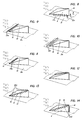
- Fig. 1 50 is a jacketed plenum, which generally receives the combustion air delivered by a compressor, not shown, and supplies it to an annular combustion chamber 1.
- This combustion chamber is constructed in two stages and essentially consists of a pre-combustion chamber 61 and a downstream post-combustion chamber 172, both of which are encased with a combustion chamber wall 63, 63 '.
- an annular dome 55 is placed on the pre-combustion chamber 61, which is located at the head end of the combustion chamber 1 and its combustion chamber through a front plate 54 is limited.
- a burner 110 is arranged in this dome in such a way that the burner outlet is at least approximately flush with the front plate 54.
- the longitudinal axis 51 of the primary burner 110 runs in the longitudinal axis 52 of the pre-combustion chamber 61.
- a plurality, here 30, of such are distributed over the circumference Burners 110 arranged side by side on the annular front plate 54 (Fig. 2A, B).
- the combustion air flows from the plenum 50 into the interior of the dome and acts on the burners via the dome wall perforated at its outer end.
- the fuel is supplied to the burner via a fuel lance 120 which penetrates the plenum and dome walls.
- a number of secondary burners 150 open into the after-combustion chamber. These are also premix burners. Their longitudinal axis 153 extends at an angle of, for example, approximately 30 ° to the longitudinal axis of the pre-combustion chamber 61. In the present example, the cross-sections through which the primary burners 110 and secondary burners 150 flow are dimensioned for approximately half of the total volume flow to be processed.
- a gaseous and / or liquid fuel is injected into the combustion air in the channel 154 of the secondary burner 150.
- the latter also reaches channel 154 via plenum 50, which is not shown. It is guided via vortex generators 9, 9a, of which several are arranged side by side in two channel levels over the circumference.
- the secondary burners 150 are arranged radially on the outside. This radial staggering creates a compact combustion chamber.
- swirl-generating troughs 161 are provided on the combustion chamber wall 63 'of the pre-combustion chamber.
- the transition from the pre-combustion chamber 61 to the post-combustion chamber 172 is provided with a constriction 171 on the combustion chamber wall 63 opposite the confluence of the secondary burners 150.
- the confluence of the secondary burners in the post-combustion chamber 172 is selected such that the mixture has not yet completely burned out in the pre-combustion chamber 61.
- an equal number, here 30 pieces, of primary burners 110 and secondary burners 150 is arranged over the circumference.
- their axes are offset by half a division in the circumferential direction.
- the axes of the primary burner 110 and secondary burner 150 lie on the same radial. It is understood that the number and arrangements shown are not mandatory.
- the mixture was completely burned out in the afterburning chamber 172.
- the hot flue gases then reach the turbine inlet 173 via a transition zone ZT, in which they are accelerated and generally mixed with cooling air.
- premix burners 110 are in each case a so-called double-cone burner, as was already mentioned above and is known for example from EP-B1-0 321 809. It essentially consists of two hollow, conical partial bodies 111, 112, which are nested in the flow direction and thereby enclose the premixing chamber 115.
- the respective central axes 113, 114 of the two partial bodies are offset from one another.
- the adjacent walls of the two partial bodies form in their longitudinal extension tangential slots 119 for the combustion air, which in this way reaches the interior of the burner, ie the premixing chamber 115.
- a first central fuel nozzle 116 for liquid fuel is arranged there. The fuel is injected into the hollow cone at an acute angle.
- the resulting conical fuel profile is enclosed by the combustion air flowing in tangentially.
- the concentration of the fuel is continuously reduced in the axial direction due to the mixing with the combustion air.
- the burner is also operated with gaseous fuel.
- gas inflow openings 117 distributed in the longitudinal direction are provided in the region of the tangential slots 119 in the walls of the two partial bodies. In gas operation, the mixture formation with the combustion air thus already begins in the zone of the inlet slots 119. It goes without saying that mixed operation with both types of fuel is also possible in this way.
- a fuel concentration that is as homogeneous as possible is established over the applied annular cross section.
- a defined dome-shaped recirculation zone 123 is formed, at the tip of which the ignition takes place. The flame itself is stabilized by the recirculation zone in front of the burner without the need for a mechanical flame holder.
- the secondary burner 150 should now be a non-self-operating premix burner. This is understood to mean that permanent ignition must be present for the mixture combustion of the secondary burner. In the present case, this permanent ignition takes place via the flame at the outlet of the pre-combustion chamber 61. When driving with low partial loads, only the primary burners are operated with fuel. The main flow of the secondary burners is then used as dilution air.
- a vortex generator essentially consists of three free-flowing triangular surfaces. These are a roof surface 10 and two side surfaces 11 and 13. In their longitudinal extension, these surfaces run at certain angles in the direction of flow.
- the side walls of the vortex generator which consist of right-angled triangles, are fixed with their long sides on a channel wall 21, preferably gas-tight. They are oriented so that they form a joint on their narrow sides, including an arrow angle ⁇ .
- the joint is designed as a sharp connecting edge 16 and is perpendicular to that channel wall 21 with which the side surfaces are flush.
- the two enclosing the arrow angle ⁇ 4, side surfaces 11, 13 are symmetrical in shape, size and orientation and are arranged on both sides of an axis of symmetry 17. This axis of symmetry 17 is rectified like the channel axis.
- the roof surface 10 lies with a very narrow edge 15 running transversely to the flow through the channel on the same channel wall 21 as the side walls 11, 13. Its longitudinal edges 12, 14 are flush with the longitudinal edges of the side surfaces projecting into the flow channel.
- the roof surface extends at an angle of inclination ⁇ to the channel wall 21. Its longitudinal edges 12, 14 form a tip 18 together with the connecting edge 16.
- the vortex generator can also be provided with a bottom surface with which it is fastened in a suitable manner to the channel wall 21.
- a floor area is not related to the mode of operation of the element.
- the connecting edge 16 of the two side surfaces 11, 13 forms the downstream edge of the vortex generator 9.
- the edge 15 of the roof surface 10 which runs transversely to the flow through the channel is thus the edge which is first acted upon by the channel flow.
- the vortex generator works as follows: When flowing around edges 12 and 14, the main flow is converted into a pair of opposing vortices. Their vortex axes lie in the axis of the main flow. The number of swirls and the location of the vortex breakdown (if the latter is desired at all) are determined by appropriate selection of the angle of attack ⁇ and the arrow angle ⁇ . With increasing angles, the vortex strength or the number of swirls is increased and the location of the vortex bursting moves upstream into the area of the vortex generator themselves. Depending on the application, these two angles ⁇ and ⁇ are determined by the design and by the process itself. Then only the length L of the element and the height h of the connecting edge 16 need to be adjusted (FIG. 7).
- FIG. 5 shows a so-called "half" vortex generator 9a based on a vortex generator according to FIG. 4.
- only one of the two side surfaces, namely surface 11, is provided with the arrow angle ⁇ / 2.
- the other side surface 13 is straight and aligned in the direction of flow.
- only one vortex is generated on the arrowed side. Accordingly, there is no vortex-neutral field downstream of this vortex generator 9a, but a swirl is forced on the flow.
- the sharp connecting edge 16 of the vortex generator 9b is the point which is first acted upon by the channel flow.
- the element is rotated by 180 °.
- the two opposite vortices have changed their sense of rotation.
- the vortex generators 9 are installed in a channel 154.
- the height h of the connecting edge 16 will be coordinated with the channel height H - or the height of the channel part which is assigned to the vortex generator - in such a way that the vortex generated immediately downstream of the vortex generator already reaches such a size that the full channel height H is filled. This leads to a uniform speed distribution in the cross-section applied.
- Another criterion that can influence the ratio h / H to be selected is the pressure drop that occurs when the vortex generator flows around. It goes without saying that the pressure loss coefficient also increases with a larger ratio h / H.
- two vortex generators 9 and 9b are provided in each of the 30 secondary burners in the outlet area. They are distributed over the circumference of the corresponding circular ring segment without a gap.
- the vortex generators could also be strung together on their respective wall segments in the circumferential direction in such a way that gaps between the boundary wall and the side walls are left free.
- the vortex to be generated is decisive here.
- the radially outer vortex generators 9 according to FIG. 4 are arranged, so that their leading edges 15 are first acted upon by the flow.
- the radially inner vortex generators 9b are oriented according to FIG. 6, ie the connecting edges 16 are acted upon first by the flow here.
- the resulting flow field within the circular ring segment is again identified by arrows. It can be seen that the total flow is likewise directed radially inward, but not along the boundary walls 155 on the outside, but in the middle of the segment.
- the vortex generators are therefore mainly used to mix two flows.
- the main flow in the form of combustion air attacks the transverse inlet edges 15 and the connecting edges 16 in the direction of the arrow.
- the secondary flow in the form of a gaseous and / or liquid fuel generally has a substantially smaller mass flow than the main flow, provided that it is not a low-calorie fuel such as for example top gas. In the present case, it is introduced into the main flow upstream of the vortex generators 9 and 9a on the outlet side.
- the fuel is injected into the secondary burners 150 via a central fuel lance 151.
- a cross-jet injection of the fuel is shown, the fuel pulse having to be approximately twice that of the main flow.
- a longitudinal injection in the direction of flow could just as well be provided. In this case, the injection pulse corresponds approximately to that of the main flow pulse.
- the injected fuel is dragged along by the vortices and mixed with the main flow. It follows the helical course of the vertebrae and is evenly finely distributed in the chamber downstream of the vertebrae. This reduces the risk of impinging jets on the opposite wall and the formation of so-called "hot spots" - in the case of the radial injection of fuel into an undisturbed flow mentioned at the beginning.
- the fuel injection can be kept flexible and adapted to other boundary conditions. In this way, the same injection pulse can be maintained throughout the load range. Since the mixing is determined by the geometry of the vortex generators and not by the machine load, in this case the gas turbine output, the burner configured in this way works optimally even under partial load conditions.
- the combustion process will by adjusting the ignition delay time of the fuel and the mixing time of the vortices, which ensures a minimization of emissions.
- the fuel can also be supplied to the channel 154 in another way. 1, it is possible to introduce the fuel directly into the area of the vortex generators via gas supply channels 152.
- FIGS. 8 to 14 show such possible forms of introducing the fuel into the combustion air with regard to the secondary burners. These variants can be combined with each other and with a central fuel injection in a variety of ways.
- the fuel in addition to wall bores 22a downstream of the vortex generators, the fuel is injected via wall bores 22c which are located directly next to the side walls 11, 13 and in their longitudinal extent in the same wall 21 on which the vortex generators are arranged are. Introducing the fuel through the wall bores 22c gives the generated vortices an additional impulse, which extends its life.
- the fuel is injected on the one hand via a slot 22e or via wall bores 22f, which are located directly in front of the edge 15 of the roof surface 10 running transversely to the flow channel and in its longitudinal extent in the same wall 21 on which the eddies are located Generators are arranged.
- the geometry of the wall bores 22f or of the slot 22e is selected such that the fuel is injected into the main flow at a specific injection angle and the subsequent vortex generator flows around as a protective film against the hot main flow.
- the secondary flow is first introduced through the channel wall 21 into the hollow interior of the vortex generator by means not shown. This creates an internal cooling facility for the vortex generators.
- the fuel is injected via wall bores 22g, which are located within the roof area 10 directly behind the edge 15 running transversely to the flowed channel and in its longitudinal extent.
- the vortex generator is cooled more externally than internally.
- the secondary flow emerging forms a protective layer shielding the hot main flow when it flows around the roof surface 10.
- the fuel is injected via wall bores 22h, which are staggered within the roof surface 10 along the line of symmetry 17.
- the channel walls are particularly well protected from the hot main flow, since the fuel is first introduced on the outer circumference of the vortex.
- the fuel is injected via wall bores 22j, which are located in the longitudinal edges 12, 14 of the roof surface 10.
- This solution ensures good cooling of the vortex generators, since the fuel escapes from its extremities and thus completely flushes the inner walls of the element.
- the secondary flow is fed directly into the resulting vortex, which leads to defined flow conditions.
- the injection takes place via wall bores 22d, which are located in the side surfaces 11 and 13 on the one hand in the area the longitudinal edges 12 and 14 and on the other hand in the area of the connecting edge 16.
- This variant is similar in effect to that from the bores 22a in FIG. 8 and from the bores 22j in FIG. 13.
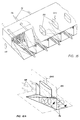
- Fig. 15 shows a partial perspective view of the meeting of the secondary burners and the pre-combustion chamber.
- the vortex generators provided here in the outlet area of the secondary burners correspond to those according to FIG. 2A.
- the radially inner "half" vortex generators 9a shown are flowed to first with the connecting edge 16, which is here in the same radial as the segment boundary wall 155; the radially outer "half" vortex generators 9a are first flowed over with the edge 15 running in the circumferential direction.
- vortex-generating troughs 161 are provided at the outlet of the pre-combustion chamber 61 in the region of the confluence of the secondary burners 150 on the combustion chamber wall 63 'of the pre-combustion chamber and are constructed similarly to the vortex generators described so far. In contrast to these, the two side surfaces and the roof surface do not form a specific tip. As shown in FIG. 1, the radially outer flow of the pre-combustion chamber is swirled radially outward by these stepped troughs and impinges on the mixture of secondary burners flowing inwards.
- the transition from the pre-combustion chamber 61 to the afterburning chamber 62 is provided with a constriction 171 on the combustion chamber wall 63 opposite the troughs 161, so as not to disturb the surface conditions.
- Fig. 16 shows a partial perspective view of the entrance of the secondary burner, again in this first level half vortex generators 9a are arranged according to FIG. 5, but in a different arrangement than that at the secondary burner outlet.
- a central fuel lance 151 for oil and gas feed pipe 156 to the vortex generators are provided for the individual burners.
- 16A which shows a detailed view of FIG. 16, shows the eddy formation on both sides of the radially running segment boundary wall 155; the fact that the half vortex generators arranged next to one another in the circumferential direction alternately act upon the edge 15 and the edge 16 by the air first, creates a total vortex in the same direction in the counterclockwise direction.
- the vortex generators in the secondary burners can be designed so that recirculation zones downstream are largely avoided. As a result, the residence time of the fuel particles in the hot zones is very short, which has a favorable effect on the minimal formation of NOx.
- the vortex generators can also be designed and staggered in the depth of the channel 154 in such a way that a defined backflow zone 170 arises at the outlet of the secondary burners, which stabilizes the flame in an aerodynamic manner, i.e. without mechanical flame holder.
- the mixture leaves the secondary burner 150 with a vortex and enters the flame from the pre-combustion chamber 61.
- the mixture leaves the secondary burner 150 with a vortex and enters the flame from the pre-combustion chamber 61.
- the collision of the two eddy currents there is intimate mixing over the shortest distance and a renewed vortex burst, which leads to the backflow zone 170 already mentioned.
- the intensive mixing results in a good temperature profile over the cross-section through which the air flows and also reduces the possibility of thermoacoustic instability. Due to their presence alone, the vortex generators act as a damping measure against thermoacoustic vibrations.
- the partial load operation of combustion chambers can be easily implemented by means of a graduated fuel supply to the individual modules. If only the primary burners are operated with a premix flame, the main flow of the secondary burners is used as dilution air. This strongly swirled main flow mixes very quickly with the hot gases emerging from the primary stage at the outlet of the secondary burners. A uniform temperature profile is thus generated downstream.
- fuel is gradually injected into the secondary burner and mixed intensively into the combustion air before ignition. So these secondary burners always work in premix mode; they are ignited and stabilized from the primary burners.
- the burner aerodynamics consist of two radially graded vortex images.
- the radially outer vortices depend on the number and geometry of the vortex generators 9.
- the radially inner vortex structure emanating from the double-cone burner can be influenced by adapting certain geometric parameters on the double-cone burner.
- the quantity distribution between the primary burner and the secondary burner can be carried out as required by appropriately coordinating the areas through which the flow flows, taking into account the pressure losses. Because the vortex generators have a relatively low pressure drop, the secondary burners can flow through at a higher speed than the primary burner. A higher speed at the outlet of the secondary burner has a favorable effect on the flame's kickback.
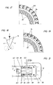
- FIG. 17 An annular combustion chamber is proposed in FIG. 17 , in which the radially stepped vortex images described above are precisely defined.
- the radially inner large-scale vortex and the radially outer vortex have the opposite direction of rotation.
- a number of vortex generators 9a according to FIG. 5 are grouped around the double-cone burner 101. These are so-called half vortex generators, in which only one of the two side surfaces of the vortex generator 9a is provided with the arrow angle ⁇ / 2. The other side surface is straight and aligned in the burner axis. In contrast to the symmetrical vortex generator, only one vortex is generated on the arrowed side.
- FIGS. 18 and 19 show a top view of an embodiment variant of a vortex generator 9c and a front view of its arrangement in an annular channel.
- the two side surfaces 11 and 13 enclosing the arrow angle ⁇ have a different length.
- the vortex generator then naturally has a different angle of attack stell across its width.
- Such a variant has the effect that vertebrae with different Strength are generated. For example, this can act on a swirl adhering to the main flow. Or, due to the different vortices, a swirl is forced on the originally swirl-free main flow downstream of the vortex generators.
- Such configurations are well suited as an independent, compact burner unit.
- the swirl imposed on the main flow can be exploited to improve the cross-ignition behavior of the burner configuration, e.g. at partial load.
- 173 (as in FIG. 1) denotes the first turbine guide vane row.
- the effect of the new measure is as follows: On the occasion of the pre-combustion, as a result of the split in half between the primary burner and secondary burner, only half of the total volume flow as a result of the temperature increase ⁇ T 1C produces nitrogen. This half volume flow has only a short dwell time in the pre-combustion chamber 61 until it is mixed with the mixture from the secondary burners, which has a favorable effect on the NO x production.
- the mixing temperature must not drop below the compression ignition temperature T SI .
- the invention is not limited to the use of primary burners of the double-cone type shown. Rather, it can be used in all combustion chamber zones in which flame stabilization is generated by a prevailing air velocity field.
- FIG. 21 As another example of this, reference is made to the burner shown in FIG. 21.
- all functionally identical elements are provided with the same reference numerals as in the burner according to FIGS. 1-3B. This is despite a different structure, which applies in particular to the tangential inflow gaps 119 which run here cylindrically.
- the area of the premixing chamber 115 which flows through in the direction of the burner outlet is formed in this burner by a centrally arranged insert 130 in the form of a straight circular cone, the cone tip being in the region of the front plate plane. It goes without saying that the lateral surface of this cone can also be curved. Incidentally, this also applies to the course of the partial surfaces 111, 112 in the burners shown in FIGS. 1-3B.
Abstract
Description
Die Erfindung betrifft eine Brennkammer mit zweistufiger Verbrennung, mit mindestens einem Primärbrenner der Vormischbauart, bei dem innerhalb eines Vormischraumes der über Düsen eingespritzte Brennstoff vorgängig der Zündung mit der Brennluft intensiv vermischt wird, und mit mindestens einem Sekundärbrenner, der stromabwärts einer Vorbrennkammer angeordnet ist.The invention relates to a combustion chamber with two-stage combustion, with at least one primary burner of the premix type, in which the fuel injected via nozzles is intensively mixed with the combustion air prior to ignition within a premixing chamber, and with at least one secondary burner which is arranged downstream of a pre-combustion chamber.
Die Verbrennung mit der grösstmöglichen Luftüberschusszahl, - einmal dadurch gegeben, dass die Flamme überhaupt noch brennt und im weiteren dadurch, dass nicht zuviel CO entsteht - vermindert nicht nur die Schadstoffmenge an NOx, sondern bewirkt darüberhinaus auch die Tiefhaltung anderer Schadstoffe, nämlich von CO und von unverbrannten Kohlenwasserstoffen. Dies erlaubt die Wahl einer grösseren Luftüberschusszahl, wobei dann zwar zunächst grössere Mengen CO entstehen, diese aber zu CO2 weiter reagieren können, so dass schliesslich die CO-Emissionen gering bleiben. Andererseits aber bildet sich wegen des grossen Luftüberschusses nur wenig zusätzliches NO. Da in einer Brennkammer für beispielsweise Gasturbinen in der Regel eine grössere Anzahl Brenner angeordnet sind, werden bei der Lastregelung jeweils nur soviele Elemente mit Brennstoff betrieben, dass sich für die jeweiliege Betriebsphase (Start, Teillast, Vollast) die optimale Luftüberschusszahl ergibt.Combustion with the largest possible excess of air, given that the flame is still burning at all and furthermore that not too much CO is produced, not only reduces the amount of NO x pollutants, but also lowers other pollutants, namely CO and unburned hydrocarbons. This allows a larger excess air number to be selected, in which case larger amounts of CO are initially generated, but these can react further to CO 2 , so that ultimately the CO emissions remain low. On the other hand, due to the large excess of air, little additional NO is formed. Since a larger number of burners are usually arranged in a combustion chamber for, for example, gas turbines, only so many elements are operated with fuel in the load control that are suitable for the respective operating phase (start, partial load, full load) gives the optimal excess air figure.
Um eine verlässliche Zündung des Gemischs in der nachgeschalteten Brennkammer und einen genügenden Ausbrand zu erzielen, ist eine innige Mischung des Brennstoffs mit der Luft erforderlich. Eine gute Durchmischung trägt auch dazu bei, sogenannte "hot spots" in der Brennkammer zu vermeiden, die unter anderem zur Bildung des unerwünschten NOX führen. Aus diesem Grund werden zunehmend zweistufige Brennkammern mit Vormischbrennern der eingangs genannten Art in der Primärstufe eingesetzt.In order to achieve a reliable ignition of the mixture in the downstream combustion chamber and a sufficient burnout, an intimate mixture of the fuel with the air is required. A good mixing also helps to avoid so-called "hot spots" in the combustion chamber, which among other things lead to the formation of the undesired NO x . For this reason, two-stage combustion chambers with premix burners of the type mentioned at the outset are increasingly being used in the primary stage.
Die einstufigen Brennkammern mit Vormischbrennern weisen nämlich die Unzulänglichkeit auf, dass zumindest in den Betriebszuständen, in denen nur ein Teil der Brenner mit Brennstoff betrieben wird, oder bei denen die einzelnen Brenner mit einer verringerten Brennstoffmenge beaufschlagt werden, nahe an die Grenze der Flammenstabilität gestossen wird. In der Tat wird die Löschgrenze aufgrund des sehr mageren Gemisches und der sich daraus ergebenden niedrigen Flammentemperatur bei typischen Gasturbinenbedingungen schon bei einer Luftüberschusszahl von etwa 2,0 erreicht.The single-stage combustion chambers with premix burners have the inadequacy that, at least in the operating states in which only some of the burners are operated with fuel, or in which the individual burners are supplied with a reduced amount of fuel, the flame stability is pushed close to the limit . In fact, due to the very lean mixture and the resulting low flame temperature under typical gas turbine conditions, the extinguishing limit is already reached with an excess air ratio of approximately 2.0.
Diese Tatsache führt zu einer relativ komplizierten Fahrweise der Brennkammer mit entsprechend aufwendiger Regelung. Eine andere Möglichkeit, den Betriebsbereich von Vormischbrennern zu erweitern, wird in der Stützung des Brenners mittels einer kleinen Diffusionsflamme gesehen. Diese Pilotflamme erhält ihren Brennstoff rein, oder zumindest schlecht vorgemischt, was einerseits zwar zu einer stabilen Flamme führt, andererseits jedoch die für Diffusionsverbrennung typischen hohen NOx-Emissionen zur Folge hat.This fact leads to a relatively complicated operation of the combustion chamber with a correspondingly complex regulation. Another way of expanding the operating range of premix burners is to support the burner with a small diffusion flame. This pilot flame receives its fuel pure, or at least poorly premixed, which on the one hand leads to a stable flame but on the other hand results in the high NO x emissions typical of diffusion combustion.
Sowohl im Ölbetrieb bei sehr hohem Druck als auch im Gasbetrieb mit stark wasserstoffhaltigen Gasen kann es bei Vormischbrennern vorkommen, dass die Zündverzugszeiten derart kurz werden, dass flammhaltende Brenner nicht mehr als sogenannte Low-Nox-Brenner einsetzbar sind.In premix burners, it can be used both in oil operation at very high pressure and in gas operation with gases that contain a lot of hydrogen occur that the ignition delay times become so short that flame-retardant burners can no longer be used as so-called low-nox burners.
Die Einmischung von Brennstoff in eine in einem Vormischkanal strömenden Brennluftströmung geschieht in der Regel durch radiale Eindüsung des Brennstoffs in den Kanal mittels Querstrahlmischern. Der Impuls des Brennstoffs ist indes so gering, dass eine nahezu vollständige Durchmischung erst nach einer Strecke von ca. 100 Kanalhöhen erfolgt ist. Auch Venturimischer kommen zur Anwendung. Bekannt ist auch die Eindüsung des Brennstoffs über Gitteranordnungen. Schliesslich wird auch das Eindüsen vor besonderen Drallkörpern angewendet.The mixing of fuel into a combustion air flow flowing in a premixing duct is usually done by radial injection of the fuel into the duct by means of cross jet mixers. However, the momentum of the fuel is so low that an almost complete mixing takes place only after a distance of approximately 100 channel heights. Venturi mixers are also used. The injection of the fuel via grid arrangements is also known. Finally, spraying in front of special swirl bodies is also used.
Die auf der Basis von Querstrahlen oder Schichtströmungen arbeitende Vorrichtungen haben entweder sehr lange Mischstrecken zur Folge oder verlangen hohe Einspritzimpulse. Bei Vormischung unter hohem Druck und unterstöchiometrischen Mischverhältnissen besteht die Gefahr von Rückschlagen der Flamme oder gar von Selbstzündung des Gemischs. Strömungsablösungen und Totwasserzonen im Vormischrohr, dicke Grenzschichten an den Wandungen oder eventuell extreme Gechwindigkeitsprofile über dem durchströmten Querschnitt können die Ursache für Selbstzündung im Rohr sein oder Pfade bilden, über die die Flamme aus der stromab liegenden Verbrennungszone in das Vormischrohr zurückschlagen kann. Der Geometrie der Vormischstrecke muss demnach höchste Beachtung geschenkt werden.The devices operating on the basis of transverse jets or stratified flows either result in very long mixing distances or require high injection pulses. With premixing under high pressure and substoichiometric mixing ratios, there is a risk of the flame flashing back or even of self-ignition of the mixture. Flow separations and dead water zones in the premixing tube, thick boundary layers on the walls or possibly extreme speed profiles over the cross-section through which the flow is flowing can be the cause of auto-ignition in the tube or form paths through which the flame can strike back from the downstream combustion zone into the premixing tube. The geometry of the premixing section must therefore be given the greatest attention.
Die oben erwähnte Eindüsung des Brennstoffs über klassische Mittel wie beispielsweise Querstrahlmischer ist schwierig, da der Brennstoff selbst einen ungenügenden Impuls aufweist, um die erforderliche gross-skalige Verteilung und die feinskalige Mischung zu erreichen.The above-mentioned injection of the fuel using conventional means, such as, for example, a cross-jet mixer, is difficult since the fuel itself has an insufficient impulse to achieve the required large-scale distribution and the fine-scale mixture.
Die Erfindung versucht all diese Nachteile zu vermeiden. Ihr liegt insbesondere die Aufgabe zugrunde, eine emissionsarme Sekundärverbrennung zu schaffen.The invention tries to avoid all these disadvantages. It is particularly based on the task of creating low-emission secondary combustion.
Erfindungsgemäss wird dies dadurch erreicht, dass der Primärbrenner ein flammenstabilisierender Vormischbrenner ohne mechanischen Flammenhalter ist, mit zumindest annähernd tangentialer Einströmung der Brennluft in den Vormischraum, und dass der Sekundärbrenner ein nicht selbstgängiger Vormischbrenner ist.According to the invention, this is achieved in that the primary burner is a flame-stabilizing premix burner without a mechanical flame holder, with at least approximately tangential inflow of the combustion air into the premixing chamber, and in that the secondary burner is a non-self-sufficient premix burner.
Solche flammenhaltende Vormischbrenner können beispielsweise die Brenner der sogenannten Doppelkegelbauart sein, wie sie aus der EP-B1-0 321 809 bekannt sind und später zu Fig. 1 bis 3B beschrieben werden. Der Brennstoff, dort Gas, wird in den tangential verlaufenden Eintrittsspalten in die vom Verdichter heranströmende Verbrennungsluft über eine Reihe von Injektordüsen eingespritzt. Diese sind in der Regel über die ganzen Spalte gleichmässig verteilt.Such flame-holding premix burners can be, for example, the burners of the so-called double-cone type, as are known from EP-B1-0 321 809 and are described later in relation to FIGS. 1 to 3B. The fuel, there gas, is injected in the tangential inlet gaps into the combustion air flowing in from the compressor via a series of injector nozzles. As a rule, these are evenly distributed over the entire column.
Der Vorteil der Erfindung ist bei einer solchen Mager/Mager-Fahrweise der Brennkammer insbesondere in einer NOX-neutralen Sekundärverbrennung zu sehen.The advantage of the invention can be seen in such a lean / lean operating mode of the combustion chamber in a particular NO X-neutral secondary combustion.
Dadurch, dass die Brenner bei sehr magerem Gemisch betriebsfähig bleiben, kann auch die Regelung insofern vereinfacht werden, als beim Belasten und Entlasten der Brennkammer Luftzahlbereiche durchquert werden können, die mit der bisherigen Vormischverbrennung in der Regel nicht durchfahren werden konnten, ohne dass mit separaten Mitteln ein Löschen der Flamme vermieden werden muss.Because the burners remain operational when the mixture is very lean, the control can also be simplified insofar as the combustion chamber is loaded and unloaded, it is possible to cross air ratio ranges which, as a rule, could not be traversed with the previous premix combustion without using separate means extinguishing the flame must be avoided.
Um die notwendige innige Vermischung zu erreichen, wird in den Kanal des Sekundärbrenners ein gasförmiger und/oder flüssiger Brennstoff in die Verbrennungsluft eingedüst, wobei die Verbrennungsluft über Wirbelgeneratoren geführt wird, von denen über dem Umfang des durchströmten Kanals mehrere nebeneinander angeordnet sind.In order to achieve the necessary intimate mixing, a gaseous and / or liquid fuel is injected into the combustion air in the channel of the secondary burner, the combustion air being conducted via vortex generators, several of which are arranged next to one another over the circumference of the channel through which the flow passes.
Diese Wirbel-Generatoren zeichnen sich durch eine Dachfläche und zwei Seitenflächen aus, wobei die Seitenflächen mit einer gleichen Kanalwand bündig sind und miteinander einen Pfeilwinkel α einschliessen und wobei die längsgerichteten Kanten der Dachfläche bündig sind mit den in den Strömungskanal hineinragenden längsgerichteten Kanten der Seitenflächen und unter einem Anstellwinkel Θ zur Kanalwand verlaufen.These vortex generators are characterized by a roof surface and two side surfaces, the side surfaces being flush with the same channel wall and including an arrow angle α and the longitudinal edges of the roof surface being flush with the longitudinal edges of the side surfaces projecting into the flow channel and below an angle of attack Θ to the duct wall.
Mit dem neuen statischen Mischer, den die 3-dimensionalen Wirbel-Generatoren darstellen, ist es möglich, in den Sekundärbrennern ausserordentlich kurze Mischstrecken bei gleichzeitig geringem Druckverlust zu erzielen. Durch die Erzeugung von Längswirbel ohne Rezirkulationsgebiet ist bereits nach einer vollen Wirbelumdrehung eine grobe Durchmischung der beiden Ströme vollzogen, während eine Feinmischung infolge turbulenter Strömung und molekularer Diffusionsprozesse bereits nach einer Strecke vorliegt, die einigen wenigen Kanalhöhen entspricht.With the new static mixer, which is represented by the 3-dimensional vortex generators, it is possible to achieve extremely short mixing distances in the secondary burners with a low pressure drop. The generation of longitudinal vortices without a recirculation area results in a rough mixing of the two streams after a full vortex revolution, while fine mixing due to turbulent flow and molecular diffusion processes already exists after a distance that corresponds to a few channel heights.
Diese Art der Mischung ist besonders geeignet, um den Brennstoff mit relativ geringem Vordruck unter grosser Verdünnung in die Verbrennungsluft einzumischen. Ein geringer Vordruck des Brennstoffes ist insbesondere bei der Verwendung von mittel- und niederkalorischen Brenngasen von Vorteil. Die zur Mischung erforderliche Energie wird dabei zu einem wesentlichen Teil aus der Strömungsenergie des Fluides mit dem höheren Volumenstrom, eben der Verbrennungsluft, entnommen.This type of mixture is particularly suitable for mixing the fuel into the combustion air at a relatively low admission pressure and with great dilution. A low admission pressure of the fuel is particularly advantageous when using medium and low calorific fuel gases. The energy required for mixing is largely drawn from the flow energy of the fluid with the higher volume flow, namely the combustion air.
Der Vorteil solcher Wirbel-Generatoren ist in ihrer besonderen Einfachheit zu sehen. Fertigungstechnisch ist das aus drei umströmten Wänden bestehende Element völlig problemlos. Die Dachfläche kann mit den beiden Seitenflächen auf verschiedenste Arten zusammengefügt werden. Auch die Fixierung des Elementes an ebenen oder gekrümmten Kanalwänden kann im Falle von schweissbaren Materialien durch einfache Schweissnähte erfolgen. Vom strömungstechnischen Standpunkt her weist das Element beim Umströmen einen sehr geringen Druckverlust auf und es erzeugt Wirbel ohne Totwassergebiet. Schliesslich kann das Element durch seinen in der Regel hohlen Innenraum auf die verschiedensten Arten und mit diversen Mitteln gekühlt werden.The advantage of such vortex generators can be seen in their particular simplicity. In terms of production technology, the element consisting of three walls with flow around it is completely problem-free. The roof surface can be joined with the two side surfaces in a variety of ways. The element can also be fixed to flat or curved channel walls in the case of weldable materials by simple weld seams. From a fluidic point of view, the element has a very low pressure drop when flowing around and it creates vortices without a dead water area. Finally, due to its generally hollow interior, the element can be cooled in a variety of ways and with various means.
Es ist angebracht, das Verhältnis Höhe h der Verbindungskante der beiden Seitenflächen zur Kanalhöhe H so zu wählen, dass der erzeugte Wirbel unmittelbar stromabwärts des Wirbel-Generators die volle Kanalhöhe oder die volle Höhe des dem Wirbel-Generator zugeordneten Kanalteils ausfüllt.It is appropriate to choose the ratio height h of the connecting edge of the two side surfaces to the channel height H so that the vortex generated fills the full channel height or the full height of the channel part assigned to the vortex generator immediately downstream of the vortex generator.
Wenn die Symmetrieachse parallel zur Kanalachse verläuft, und die Verbindungskante der beiden Seitenflächen die stromabwärtige Kante des Wirbel-Generators bildet, während demzufolge die quer zum durchströmten Kanal verlaufende Kante der Dachfläche die von der Kanalströmung zuerst beaufschlagte Kante ist, so werden an einem Wirbel-Generator zwei gleiche,jedoch gegenläufige Wirbel erzeugt. Es liegt ein drallneutrales Strömungsbild vor, bei welchem der Drehsinn der beiden Wirbel im Bereich der Verbindungskante aufsteigend ist.If the axis of symmetry runs parallel to the channel axis, and the connecting edge of the two side surfaces forms the downstream edge of the vortex generator, whereas the edge of the roof surface which runs transversely to the channel through which the flow is flowing is the edge first acted upon by the channel flow, then a vortex generator two identical but opposite vortices are generated. There is a swirl-neutral flow pattern in which the direction of rotation of the two vortices is ascending in the area of the connecting edge.
Weitere Vorteile der Erfindung, insbesondere im Zusammenhang mit der Anordnung der Wirbel-Generatoren und der Einführung des Brennstoffs ergeben sich aus den Unteransprüchen.Further advantages of the invention, in particular in connection with the arrangement of the vortex generators and the introduction of the fuel, result from the subclaims.
In der Zeichnung ist ein Ausführungsbeispiel der Erfindung anhand einer Ringbrennkammer für eine Gasturbine schematisch dargestellt.In the drawing, an embodiment of the invention is shown schematically using an annular combustion chamber for a gas turbine.
Es zeigen:
- Fig. 1
- einen Teillängsschnitt einer Brennkammer;
- Fig. 2A
- einen Teilquerschnitt durch die Brennkammer nach Linie 2-2 in Fig. 1;
- Fig. 2B
- einen Teilquerschnitt durch eine Anordnungsvariante der Wirbel-Generatoren in den Sekundärbrennern;
- Fig. 3A
- einen Querschnitt durch einen Vormischbrenner der Doppelkegel-Bauart im Bereich seines Austritts;
- Fig. 3B
- einen Querschnitt durch denselben Vormischbrenner im Bereich der Kegelspitze;
- Fig. 4
- eine perspektivische Darstellung eines Wirbel-Generators;
- Fig. 5
- eine Ausführungsvariante des Wirbel-Generators;
- Fig. 6
- eine Anordnungsvariante des Wirbel-Generators nach Fig. 4;
- Fig. 7
- einen Wirbel-Generator in einem Kanal;
- Fig. 8
bis 14 - Varianten der Brennstoffzuführung;
- Fig. 15
- eine perspektivische Teilansicht vom Austritt der Sekundärbrenner;
- Fig. 16
- eine perspektivische Teilansicht vom Eintritt der Sekundärbrenner mit Brennstoffzufuhr;
- Fig. 16A
- die Wirbelbildung am Eintritt der Sekundärbrenner;
- Fig. 17
- eine Anordnungsvariante von nebeneinanderangeordneten Wirbel-Generatoren;
- Fig. 18
- eine weitere Ausführungsvariante des Wirbel-Generators;
- Fig. 19
- eine Anordnungsvariante von nebeneinanderangeordneten Wirbel-Generatoren nach Fig. 17;
- Fig. 20
- ein Schaubild Temperatur längs der Brennkammer-Erstreckung;
- Fig. 21
- eine Ausführungsvariante des Primärbrenners.
- Fig. 1
- a partial longitudinal section of a combustion chamber;
- Figure 2A
- a partial cross section through the combustion chamber along line 2-2 in Fig. 1;
- Figure 2B
- a partial cross section through an arrangement of the vortex generators in the secondary burners;
- Figure 3A
- a cross section through a premix burner of the double cone type in the region of its outlet;
- Figure 3B
- a cross section through the same premix burner in the region of the cone tip;
- Fig. 4
- a perspective view of a vortex generator;
- Fig. 5
- a variant of the vortex generator;
- Fig. 6
- a variant of the arrangement of the vortex generator according to FIG. 4;
- Fig. 7
- a vortex generator in a channel;
- 8 to 14
- Variants of fuel supply;
- Fig. 15
- a partial perspective view of the outlet of the secondary burner;
- Fig. 16
- a partial perspective view of the entry of the secondary burner with fuel supply;
- Figure 16A
- the vortex formation at the entry of the secondary burner;
- Fig. 17
- an arrangement variant of side-by-side vortex generators;
- Fig. 18
- a further embodiment of the vortex generator;
- Fig. 19
- a variant of arrangement of side-by-side vortex generators according to Fig. 17;
- Fig. 20
- a graph of temperature along the combustion chamber extension;
- Fig. 21
- a variant of the primary burner.
Es sind nur die für das Verständnis der Erfindung wesentlichen Elemente gezeigt. Nicht dargestellt sind beispielsweise die vollständige Brennkammer und deren Zuordnung zu einer Anlage. Die Strömungsrichtung der Arbeitsmittel ist mit Pfeilen bezeichnet. In den verschiedenen Figuren sind die gleichen Elemente jeweils mit den gleichen Bezugszeichen versehen. Erfindungsunwesentliche Elemente wie Gehäuse, Befestigungen, Leitungsdurchführungen, die Brennstoffbereitstellung, die Regeleinrichtungen und dergleichen sind fortgelassen.Only the elements essential for understanding the invention are shown. For example, the complete combustion chamber and its assignment to a system are not shown. The direction of flow of the work equipment is indicated by arrows. In the various figures, the same elements are provided with the same reference symbols. Elements which are not essential to the invention, such as housings, fastenings, line bushings, the provision of fuel, the control devices and the like have been omitted.
In Fig. 1 ist mit 50 ein ummanteltes Plenum bezeichnet, welches in der Regel die von einem nicht dargestellten Verdichter geförderte Verbrennungsluft aufnimmt und einer ringförmigen Brennkammer 1 zuführt. Diese Brennkammer ist zweistufig augebildet und besteht im wesentlichen aus einer Vorbrennkammer 61 und einer stromabwärts gelegenen Nachbrennkammer 172, welche beide mit einer Brennkammerwand 63, 63' ummantelt sind.In Fig. 1, 50 is a jacketed plenum, which generally receives the combustion air delivered by a compressor, not shown, and supplies it to an
Auf die Vorbrennkammer 61, die sich am Kopfende der Brennkammer 1 befindet und deren Brennraum durch eine Frontplatte 54 begrenzt ist, ist ein ringförmiger Dom 55 aufgesetzt. In diesem Dom ist ein Brenner 110 so angeordnet, dass der Brenneraustritt zumindest annähernd bündig ist mit der Frontplatte 54. Die Längsachse 51 des Primärbrenners 110 verläuft in der Längsachse 52 der Vorbrennkammer 61. Über den Umfang verteilt ist eine Mehrzahl, hier 30, von solchen Brennern 110 nebeneinander auf der kreisringförmigen Frontplatte 54 angeordnet (Fig. 2A,B). Über die an ihrem äusseren Ende gelochte Domwandung strömt die Verbrennungsluft aus dem Plenum 50 in das Dominnere und beaufschlagt die Brenner. Der Brennstoff wird dem Brenner über eine Brennstofflanze 120 zugeführt, welche die Plenum- und die Domwand durchdringt.On the
In der Ebene, in welcher die Vorbrennkammer 61 in die Nachbrennkammer 172 übergeht, mündet eine Anzahl von Sekundärbrennern 150 in die Nachbrennkammer. Hierbei handelt es sich ebenfalls um Vormischbrenner. Deren Längsachse 153 verläuft unter einem Winkel von beispielsweise ca. 30° zur Längsachse der Vorbrennkammer 61. Im vorliegenden Beispielsfall sind die durchströmten Querschnitte der Primärbrenner 110 und Sekundärbrenner 150 für jeweils ca. die Hälfte des gesamten zu verarbeitenden Volumenstroms bemessen.In the plane in which the
In den Kanal 154 der Sekundärbrenner 150 wird ein gasförmiger und/oder flüssiger Brennstoff in die Verbrennungsluft eingedüst. Letzere gelangt ebenfalls über nicht gezeigte Mittel aus dem Plenum 50 in den Kanal 154. Sie wird über Wirbelgeneratoren 9, 9a geführt, von denen in zwei Kanalebenen über dem Umfang mehrere nebeneinander angeordnet sind.A gaseous and / or liquid fuel is injected into the combustion air in the
Bei der gezeigten ringförmigen Anordnung der Primärbrenner 110 und Sekundärbrenner 150 sind die Sekundärbrenner 150 radial aussen angeordnet. Durch diese radiale Staffelung wird eine kompakte Brennkammer geschaffen.In the annular arrangement of the
Am Austritt der Vorbrennkammer 61 im Bereich der Einmündung der Sekundärbrenner 150 sind an der Brennkammerwand 63' der Vorbrennkammer wirbelerzeugende Wannen 161 vorgesehen. Der Übergang der Vorbrennkammer 61 in die Nachbrennkammer 172 ist an der der Einmündung der Sekundärbrenner 150 gegenüber liegenden Brennkammerwand 63 mit einer Einschnürung 171 versehen.At the outlet of the
Die Einmündung der Sekundärbrenner in die Nachbrennkammer 172 ist so gewählt, dass in der Vorbrennkammer 61 noch kein vollständiger Ausbrand des Gemisches stattgefunden hat.The confluence of the secondary burners in the
Wie aus den später zu beschreibenden Fig. 2A und 2B ersichtlich, ist jeweils eine gleiche Anzahl, hier 30 Stück, von Primärbrennern 110 und Sekundärbrennern 150 über dem Umfang angeordnet. In Fig. 2A sind deren Achsen um eine halbe Teilung in Umfangsrichtung gegeneinander versetzt. In Fig. 2B liegen die Achsen der Primärbrenner 110 und Sekundärbrenner 150 auf der gleichen Radialen. Es vesteht sich, dass die genannte Anzahl und gezeigten Anordnungen nicht zwingend sind.As can be seen from FIGS. 2A and 2B to be described later, an equal number, here 30 pieces, of
In der Nachbrennkammer 172 erfolgte der vollständige Ausbrand des Gemisches. Die heissen Rauchgase gelangen dann über eine Übergangszone ZT, in welcher sie beschleunigt und in der Regel mit Kühlluft vermischt werden, zum Turbineneintritt 173.The mixture was completely burned out in the
Bei den in Fig. 1, 3A und 3B schematisch dargestellten Vormischbrennern 110 handelt es sich jeweils um einen sogenannten Doppelkegelbrenner, wie er weiter oben bereits erwähnt wurde und beispielsweise aus der EP-B1-0 321 809 bekannt ist. Im wesentlichen besteht er aus zwei hohlen, kegelförmigen Teilkörpern 111, 112, die in Strömungsrichtung ineinandergeschachtelt sind und dabei den Vormischraum 115 umschliessen. Dabei sind die jeweiligen Mittelachsen 113, 114 der beiden Teilkörper gegeneinander versetzt. Die benachbarten Wandungen der beiden Teilkörper bilden in deren Längserstreckung tangentiale Schlitze 119 für die Verbrennungsluft, die auf diese Weise in das Brennerinnere, in den Vormischraum 115 also, gelangt. Dort ist eine erste zentrale Brennstoffdüse 116 für flüssigen Brennstoff angeordnet. Der Brennstoff wird in einem spitzen Winkel in die Hohlkegel eingedüst. Das entstehende kegelige Brennstoffprofil wird von der tangential einströmenden Verbrennungsluft umschlossen. In axialer Richtung wird die Konzentration des Brennstoffes fortlaufend infolge der Vermischung mit der Verbrennungsluft abgebaut. Im Beispielsfall wird der Brenner ebenfalls mit gasförmigem Brennstoff betrieben. Hierzu sind im Bereich der tangentialen Schlitze 119 in den Wandungen der beiden Teilkörper in Längsrichtung verteilte Gaseinströmöffnungen 117 vorgesehen. Im Gasbetrieb beginnt die Gemischbildung mit der Verbrennungsluft somit bereits in der Zone der Eintrittsschlitze 119. Es versteht sich, dass auf diese Weise auch ein Mischbetrieb mit beiden Brennstoffarten möglich ist.1, 3A and 3B schematically shown
Am Brenneraustritt 118 des Brenners 110 stellt sich eine möglichst homogene Brennstoffkonzentration über dem beaufschlagten kreisringförmigen Querschnitt ein. Es entsteht am Brenneraustritt eine definierte kalottenförmige Rezirkulationszone 123, an deren Spitze die Zündung erfolgt. Die Flamme selbst wird durch die Rezirkulationszone vor dem Brenner stabilisiert, ohne einen mechanischen Flammenhalter zu benötigen.At the
Gemäss der Erfindung soll nunmehr der Sekundärbrenner 150 ein nicht selbstgängiger Vormischbrenner sein. Hierunter wird verstanden, dass für die Gemischverbrennung des Sekundärbrenners eine permanente Zündung vorhanden sein muss. Diese permanente Zündung geschieht im vorliegenden Fall über die Flamme am Austritt der Vorbrennkammer 61. Bei Fahrweise mit niedrigen Teillasten werden nur die Primärbrenner mit Brennstoff betrieben. Die Hauptsrömung der Sekundärbrenner wird dann als Verdünnungsluft benutzt.According to the invention, the
Bevor auf den Einbau der Mischvorrichtung in den Sekundärbrennern 150 eingegangen wird, wird zunächst der für den Mischvorgang wesentliche Wirbel-Generator beschrieben.Before the installation of the mixing device in the
In den Figuren 4, 5 und 6 ist der eigentliche Kanal, der von einer mit grossem Pfeil symbolisierten Hauptströmung durchströmt wird, nicht dargestellt. Gemäss diesen Figuren besteht ein Wirbel-Generator im wesentlichen aus drei frei umströmten dreieckigen Flächen. Es sind dies eine Dachfläche 10 und zwei Seitenflächen 11 und 13. In ihrer Längserstrekkung verlaufen diese Flächen unter bestimmten Winkeln in Strömungsrichtung.The actual channel, through which a main flow symbolized by a large arrow flows, is not shown in FIGS. 4, 5 and 6. According to these figures, a vortex generator essentially consists of three free-flowing triangular surfaces. These are a
Die Seitenwände des Wirbel-Generators, welche aus rechtwinkligen Dreiecken bestehen, sind mit ihren Längsseiten auf einer Kanalwand 21 fixiert, vorzugsweise gasdicht. Sie sind so orientiert, dass sie an ihren Schmalseiten einen Stoss bilden unter Einschluss eines Pfeilwinkels α. Der Stoss ist als scharfe Verbindungskante 16 ausgeführt und steht senkrecht zu jener Kanalwand 21, mit welcher die Seitenflächen bündig sind. Die beiden den Pfeilwinkel α einschliessenden Seitenflächen 11, 13 sind in Fig. 4 symmetrisch in Form, Grösse und Orientierung und sind beidseitig einer Symmetrieachse 17 angeordnet. Diese Symmetrieachse 17 ist gleichgerichtet wie die Kanalachse.The side walls of the vortex generator, which consist of right-angled triangles, are fixed with their long sides on a
Die Dachfläche 10 liegt mit einer quer zum durchströmten Kanal verlaufenden und sehr schmal ausgebildeten Kante 15 an der gleichen Kanalwand 21 an wie die Seitenwände 11, 13. Ihre längsgerichteten Kanten 12, 14 sind bündig mit den in den Strömungskanal hineinragenden längsgerichteten Kanten der Seitenflächen. Die Dachfläche verläuft unter einem Anstellwinkel Θ zur Kanalwand 21. Ihre Längskanten 12, 14 bilden zusammen mit der Verbindungskante 16 eine Spitze 18.The
Selbstverständlich kann der Wirbel-Generator auch mit einer Bodenfläche versehen sein, mit welcher er auf geeignete Art an der Kanalwand 21 befestigt ist. Eine derartige Bodenfläche steht indes in keinem Zusammenhang mit der Wirkungsweise des Elementes.Of course, the vortex generator can also be provided with a bottom surface with which it is fastened in a suitable manner to the
In Fig. 4 bildet die Verbindungskante 16 der beiden Seitenflächen 11, 13 die stromabwärtige Kante des Wirbel-Generators 9. Die quer zum durchströmten Kanal verlaufende Kante 15 der Dachfläche 10 ist somit die von der Kanalströmung zuerst beaufschlagte Kante.In FIG. 4, the connecting
Die Wirkungsweise des Wirbel-Generators ist folgende: Beim Umströmen der Kanten 12 und 14 wird die Hauptströmung in ein Paar gegenläufiger Wirbel umgewandelt. Deren Wirbelachsen liegen in der Achse der Hauptströmung. Die Drallzahl und der Ort des Wirbelaufplatzens (vortex break down), sofern letzteres überhaupt gewünscht wird, werden bestimmt durch entsprechende Wahl des Anstellwinkels Θ und des Pfeilwinkels α. Mit steigenden Winkeln wird die Wirbelstärke bzw. die Drallzahl erhöht und der Ort des Wirbelaufplatzens wandert stromaufwärts bis hin in den Bereich des Wirbel-Generators selbst. Je nach Anwendung sind diese beiden Winkel Θ und α durch konstruktive Gegebenheiten und durch den Prozess selbst vorgegeben. Angepasst werden müssen dann nur noch die Länge L des Elementes sowie die Höhe h der Verbindungskante 16 (Fig. 7).The vortex generator works as follows: When flowing around edges 12 and 14, the main flow is converted into a pair of opposing vortices. Their vortex axes lie in the axis of the main flow. The number of swirls and the location of the vortex breakdown (if the latter is desired at all) are determined by appropriate selection of the angle of attack Θ and the arrow angle α. With increasing angles, the vortex strength or the number of swirls is increased and the location of the vortex bursting moves upstream into the area of the vortex generator themselves. Depending on the application, these two angles Θ and α are determined by the design and by the process itself. Then only the length L of the element and the height h of the connecting
In Fig. 5 ist ein sogenannter "halber" Wirbel-Generator 9a auf der Basis eines Wirbel-Generators nach Fig. 4 gezeigt. Hier ist nur eine der beiden Seitenflächen, nämlich die Fläche 11, mit dem Pfeilwinkel α/2 versehen ist. Die andere Seitenfläche 13 ist gerade und in Strömungsrichtung ausgerichtet. Im Gegensatz zum symmetrischen Wirbel-Generator wird hier nur ein Wirbel an der gepfeilten Seite erzeugt. Es liegt demnach stromabwärts dieses Wirbel-Generators 9a kein wirbelneutrales Feld vor, sondern der Strömung wird ein Drall aufgezwungen.FIG. 5 shows a so-called "half"
Im Gegensatz zu Fig. 4 ist in Fig. 6 die scharfe Verbindungskante 16 des Wirbel-Generators 9b jene Stelle, die von der Kanalströmung zuerst beaufschlagt wird. Das Element ist um 180° gedreht. Wie aus der Darstellung erkennbar, haben die beiden gegenläufigen Wirbel ihren Drehsinn geändert.In contrast to FIG. 4, in FIG. 6 the sharp connecting
Gemäss Fig. 7 sind die Wirbel-Generatoren 9 in einem Kanal 154 eingebaut. In der Regel wird man die Höhe h der Verbindungskante 16 mit der Kanalhöhe H - oder der Höhe des Kanalteils, welchem dem Wirbel-Generator zugeordnet ist - so abstimmen, dass der erzeugte Wirbel unmittelbar stromabwärts des Wirbel-Generators bereits eine solche Grösse erreicht, dass die volle Kanalhöhe H ausgefüllt wird. Dies führt zu einer gleichmässigen Geschwindigkeitsverteilung in dem beaufschlagten Querschnitt. Ein weiteres Kriterium, welches Einfluss auf das zu wählende Verhältnis h/H nehmen kann, ist der Druckabfall, der beim Umströmen des Wirbel-Generators auftritt. Es versteht sich, dass mit grösserem Verhältnis h/H auch der Druckverlustbeiwert ansteigt.7, the
Im Beispiel gemäss Fig. 2A und deren Detail D2A sind bei jedem der 30 Sekundärbrenner im Austrittsbereich vier halbe Wirbel-Generatoren 9a vorgesehen. Dabei grenzen deren nicht gepfeilte Wände 13 (Fig. 5) an die radialen Brenner-Begrenzungswände 155. Das resultierende Strömungsfeld innerhalb des Kreisringsegments ist mit Pfeilen bezeichnet. Erkennbar ist, dass die Gesamtströmung radial einwärts gerichtet ist und zwar aussen an den Begrenzungswänden 155 entlang.In the example according to FIG. 2A and its detail D2A, four
Im Beispiel gemäss Fig. 2B und deren Detail D2B sind bei jedem der 30 Sekundärbrenner im Austrittsbereich zwei Wirbel-Generatoren 9 respektiv 9b vorgesehen. Sie sind ohne Abstand über dem Umfang des entsprechenden Kreisringsegments verteilt. Selbstverständlich könnten die Wirbel-Generatoren an ihren jeweiligen Wandsegmenten in Umfangsrichtung auch so aneinandergereiht sein, dass Zwischenräume zwischen Begrenzungswand und den Seitenwänden freigelassen werden. Letzlich ist hier der zu erzeugende Wirbel entscheidend.In the example according to FIG. 2B and its detail D2B, two
Aus dem Detail D2B und Fig. 1 ist erkennbar, dass die radial aussenliegenden Wirbel-Generatoren 9 nach Fig. 4 angeordnet sind, dass demnach ihre Eintrittskanten 15 von der Strömung zuerst beaufschlagt werden. Die radial innenliegenden Wirbel-Generatoren 9b sind hingegen nach Fig. 6 ausgerichtet, d. h. die Verbindungskanten 16 werden hier von der Strömung zuerst beaufschlagt. Das resultierende Strömungsfeld innerhalb des Kreisringsegments ist wiederum mit Pfeilen bezeichnet. Erkennbar ist, dass die Gesamtströmung ebenfalls radial einwärts gerichtet ist, jedoch nicht aussen an den Begrenzungswänden 155 entlang, sondern in der Segmentmitte.It can be seen from the detail D2B and FIG. 1 that the radially
Mit diesen verschiedenen Anordnungen der Wirbel-Generatoren und der Möglichkeit der Versetzung der Primärbrenner in Umfangsrichtung hat man ein Mittel in der Hand, optimale Mischbedigungen beim Aufeinandertreffen der beiden Ströme zu schaffen.With these different arrangements of the vortex generators and the possibility of displacing the primary burners in the circumferential direction, one has a means in hand to create optimal mixing conditions when the two streams meet.
Die Wirbel-Generatoren sind demnach hauptsächlich zum Mischen zweier Strömungen verwendet. Die Hauptströmung in Form von Brennluft attackiert in Pfeilrichtung die quergerichteten Eintrittskanten 15 respektiv die Verbindungskanten 16. Die Sekundärströmung in Form eines gasförmigen und/oder flüssigen Brennstoffs weist in der Regel einen wesentlich kleineren Massenstrom auf als die Hauptströmung, sofern es sich nicht um niederkalorische Brennstoffe wie beispielsweise Gichtgas handelt. Sie wird im vorliegenden Fall stromaufwärts der austrittssseitigen Wirbel-Generatoren 9 und 9a in die Hauptströmung eingeleitet.The vortex generators are therefore mainly used to mix two flows. The main flow in the form of combustion air attacks the transverse inlet edges 15 and the connecting
Zu diesem Zeitpunkt ist die Hauptströmung bereits wirbelbehaftet, da gemäss Fig. 1 stromaufwärts der zentralen Brennstofflanze 151 bereits eine Wirbel-Generatoren-Anordnung vorgesehen ist. In einer gleichen Ebene sind hier radial aussen und radial innen "halbe" Wirbel-Generatoren 9a so gestaffelt, dass die Wirbel entgegen jenen der austrittsseitigen Anordnung nunmehr in der Segmentmitte mit gleichem Drehsinn gerichtet sind.At this point in time, the main flow is already eddy, since according to FIG. 1, a vortex generator arrangement is already provided upstream of the
Es versteht sich, dass die Anzahl axial gestaffelter Wirbel-Generatoren_und damit die Länge der Sekundärbrenner abhängig ist vom Grad der gewünschten Mischqualität. Zumindest die austrittsseitigen Wirbel-Generatoren sollten neben der Mischaufgabe noch folgende Funktionen erfüllen:
- die Strömung radial einwärts lenken;
- die Strömung wie ein Venturi beschleunigen, um ein Rückschlagen der Flamme zu vermeiden. Dieses Ergebnis wird durch eine gewisse Sperrung des durchströmten Querschnittes durch die Wirbel-Generatoren erreicht;
- Stromabwärts der Sekundärbrenner ist ein Wirbelaufplatzen zur aerodynamischen Stabilisierung der Flamme vorteilhaft.
- direct the flow radially inward;
- accelerate the flow like a venturi to prevent the flame from kicking back. This result is achieved by a certain blocking of the cross section through which the vortex generators flow;
- Downstream of the secondary burners, vortexing is advantageous for aerodynamically stabilizing the flame.
Gemäss Fig. 1 wird bei den Sekundärbrennern 150 der Brennstoff über je eine zentrale Brennstofflanze 151 eingedüst. Dargestellt ist eine Querstrahleindüsung des Brennstoffes, wobei der Brennstoffimpuls etwa das Doppelte desjenigen der Hauptströmung betragen muss. Genau so gut könnte eine Längseindüsung in Strömungsrichtung vorgesehen werden. In diesem Fall entspricht der Eindüsungsimpuls etwa jenem des Hauptströmungsimpulses.1, the fuel is injected into the
Der eingedüste Brennstoff wird von den Wirbeln mitgeschleppt und mit der Hauptströmung vermischt. Er folgt dem schraubenförmigen Verlauf der Wirbel und wird stromabwärts der Wirbel in der Kammer gleichmässig feinverteilt. Dadurch reduziert sich die - bei der eingangs erwähnten radialen Eindüsung von Brennstoff in eine unverwirbelte Strömung - Gefahr von Aufprallstrahlen an der gegenüberliegenden Wand und die Bildung von sogenannten "hot spots".The injected fuel is dragged along by the vortices and mixed with the main flow. It follows the helical course of the vertebrae and is evenly finely distributed in the chamber downstream of the vertebrae. This reduces the risk of impinging jets on the opposite wall and the formation of so-called "hot spots" - in the case of the radial injection of fuel into an undisturbed flow mentioned at the beginning.
Da der hauptsächliche Mischprozess in den Wirbeln erfolgt und weitgehend unempfindlich gegen den Eindüsungsimpuls der Sekundärströmung ist, kann die Brennstoffeinspritzung flexibel gehalten werden und an andere Grenzbedingungen angepasst werden. So kann im ganzen Lastbereich der gleiche Eindüsungsimpuls beibehalten werden. Da das Mischen durch die Geometrie der Wirbel-Generatoren bestimmt wird, und nicht durch die Maschinenlast, im Beispielsfall die Gasturbinenleistung, arbeitet der so konfigurierte Brenner auch bei Teillastbedingungen optimal. Der Verbrennungsprozess wird durch Anpassen der Zündverzugszeit des Brennstoffs und der Mischzeit der Wirbel optimiert, was eine Minimierung der Emissionen gewährleistet.Since the main mixing process takes place in the vortices and is largely insensitive to the injection pulse of the secondary flow, the fuel injection can be kept flexible and adapted to other boundary conditions. In this way, the same injection pulse can be maintained throughout the load range. Since the mixing is determined by the geometry of the vortex generators and not by the machine load, in this case the gas turbine output, the burner configured in this way works optimally even under partial load conditions. The combustion process will by adjusting the ignition delay time of the fuel and the mixing time of the vortices, which ensures a minimization of emissions.
Sofern ein gasförmiger Brennstoff verbrannt werden soll, kann die Brennstoffzufuhr in den Kanal 154 auch auf andern Weg erfolgen. Es bietet sich gemäss Fig. 1 die Möglichkeit, über Gaszufuhrkanäle 152 den Brennstoff direkt im Bereich der Wirbel-Generatoren einzuleiten.If a gaseous fuel is to be burned, the fuel can also be supplied to the
Die Figuren 8 bis 14 zeigen bezüglich der Sekundärbrenner solche mögliche Formen der Einführung des Brennstoffs in die Verbrennungsluft. Diese Varianten können auf vielfältige Weise miteinander und mit einer zentralen Brennstoffeindüsung kombiniert werden.FIGS. 8 to 14 show such possible forms of introducing the fuel into the combustion air with regard to the secondary burners. These variants can be combined with each other and with a central fuel injection in a variety of ways.
Gemäss Fig. 8 wird der Brennstoff, zusätzlich zu Wandbohrungen 22a stromabwärts der Wirbel-Generatoren, über Wandbohrungen 22c eingedüst, die sich unmittelbar neben den Seitenwänden 11, 13 und in deren Längserstreckung in der gleichen Wand 21 befinden, an der die Wirbel-Generatoren angeordnet sind. Das Einleiten des Brennstoffs durch die Wandbohrungen 22c verleiht den erzeugten Wirbeln einen zusätzlichen Impuls, was seine Lebensdauer verlängert.8, in addition to wall bores 22a downstream of the vortex generators, the fuel is injected via wall bores 22c which are located directly next to the
Gemäss Fig. 9 und 10 wird der Brennstoff einerseits über einen Schlitz 22e oder über Wandbohrungen 22f eingedüst, die sich unmittelbar vor der quer zum durchströmten Kanal verlaufenden Kante 15 der Dachfläche 10 und in deren Längserstreckung in der gleichen Wand 21 befinden, an der die Wirbel-Generatoren angeordnet sind. Die Geometrie der Wandbohrungen 22f oder des Schlitzes 22e ist so gewählt, dass der Brennstoff unter einem bestimmten Einspritzwinkel in die Hauptströmung eingedüst wird und den nachfolgenden Wirbel-Generator als Schutzfilm gegen die heisse Hauptströmung umströmt.9 and 10, the fuel is injected on the one hand via a
In den nachstehend beschriebenen Beispielen wird die Sekundärströmung zunächst über nicht gezeigte Mittel durch die Kanalwand 21 ins hohle Innere des Wirbel-Generators eingeleitet. Hierdurch wird eine interne Kühlmöglichkeit für die Wirbel-Generatoren geschaffen.In the examples described below, the secondary flow is first introduced through the
Gemäss Fig. 11 wird der Brennstoff über Wandbohrungen 22g eingedüst, die sich innerhalb der Dachfläche 10 unmittelbar hinter der quer zum durchströmten Kanal verlaufenden Kante 15 und in deren Längserstreckung befinden. Die Kühlung des Wirbel-Generators erfolgt hier mehr extern als intern. Die austretende Sekundärströmung bildet beim Umströmen der Dachfläche 10 eine diese gegen die heisse Hauptströmung abschirmende Schutzschicht.11, the fuel is injected via wall bores 22g, which are located within the
Gemäss Fig. 12 wird der Brennstoff über Wandbohrungen 22h eingedüst, die innerhalb der Dachfläche 10 entlang der Symmetrielinie 17 gestaffelt angeordnet sind. Mit dieser Variante werden die Kanalwände besonders gut vor der heissen Hauptströmung geschützt, da der Brennstoff zunächst am Aussenumfang der Wirbel eingeführt wird.According to FIG. 12, the fuel is injected via wall bores 22h, which are staggered within the
Gemäss Fig. 13 wird der Brennstoff über Wandbohrungen 22j eingedüst, die sich in den längsgerichteten Kanten 12, 14 der Dachfläche 10 befinden. Diese Lösung gewährleistet eine gute Kühlung der Wirbel-Generatoren, da der Brennstoff an dessen Extremitäten austritt und somit die Innenwandungen des Elementes voll umspült. Die Sekundärströmung wird hier direkt in den entstehenden Wirbel hineingegeben, was zu definierten Strömungsverhältnissen führt.13, the fuel is injected via wall bores 22j, which are located in the
In Fig. 14 geschieht die Eindüsung über Wandbohrungen 22d, die sich in den Seitenflächen 11 und 13 einerseits im Bereich der Längskanten 12 und 14 und andererseits im Bereich der Verbindungskante 16 befinden. Diese Variante ist wirkungsähnlich wie jene aus den Bohrungen 22a in Fig. 8 und aus den Bohrungen 22j in Fig. 13.14, the injection takes place via wall bores 22d, which are located in the side surfaces 11 and 13 on the one hand in the area the
Fig. 15 zeigt eine perspektivische Teilansicht vom Zusammentreffen der Sekundärbrennern und der Vorbrennkammer. Die im Austrittsbereich der Sekundärbrenner hier vorgesehenen Wirbel-Generatoren entsprechen jenen gemäss Fig. 2A. Die gezeigten radial inneren "halben" Wirbel-Generatoren_9a werden mit der Verbindungskante 16 zuerst angeströmt, welche sich hier in der gleichen Radialen befindet wie die Segment-Begrenzungswand 155; die radial äusseren "halben" Wirbel-Generatoren 9a werden mit der in Umfangsrichtung verlaufenden Kante 15 zuerst angeströmt. Fig. 15 shows a partial perspective view of the meeting of the secondary burners and the pre-combustion chamber. The vortex generators provided here in the outlet area of the secondary burners correspond to those according to FIG. 2A. The radially inner "half"
Wie bereits oben erwähnt, sind am Austritt der Vorbrennkammer 61 im Bereich der Einmündung der Sekundärbrenner 150 an der Brennkammerwand 63' der Vorbrennkammer wirbelerzeugende Wannen 161 vorgesehen, die ähnlich aufgebaut sind wie die bisher beschriebenen Wirbel-Generatoren. Im Unterschied zu diesen bilden hier die beiden Seitenflächen und die Dachfläche keine konkrete Spitze aus. Wie Fig. 1 zeigt, wird durch diese gestuften Wannen die radial äussere Strömung der Vorbrennkammer radial auswärts verwirbelt und prallt auf das radial einwärts strömennde Gemisch aus den Sekundärbrennern.As already mentioned above, vortex-generating
Zur Kompensation dieses radial aussen ausgelenkten Teilstromes ist der Übergang der Vorbrennkammer 61 in die Nachbrennkammer 62 an der Wannen 161 gegenüber liegenden Brennkammerwand 63 mit einer Einschnürung 171 versehen, um die Flächenverhältnisse nicht zu stören.To compensate for this radially deflected partial flow, the transition from the
Fig. 16 zeigt eine perspektivische Teilansicht vom Eintritt der Sekundärbrenner, wobei in dieser ersten Ebene wiederum halbe Wirbel-Generatoren 9a gemäss Fig. 5 angeordnet sind, allerdings in einer andern Anordnung als jene am Sekundärbrenner-Austritt. Vorgesehen sind für die einzelnen Brenner je eine zentrale Brennstofflanze 151 für Öl sowie Gaszufuhrstutzen 156 zu den Wirbel-Generatoren. In Fig. 16A, welche eine Detailansicht von Fig. 16 darstellt, ist die Wirbelbildung beidseitig der radial verlaufenden Segment-Begrenzungswand 155 gezeigt; dadurch, dass die in Umfangsrichtung nebeneinanderangeordneten halben Wirbel-Generatoren abwechselnd mit der Kante 15 und der Kante 16 von der Luft zuerst beaufschlagt werden, entsteht ein gleichsinniger Gesamtwirbel im Gegenuhrzeigersinn. Fig. 16 shows a partial perspective view of the entrance of the secondary burner, again in this first level
Die Wirbel-Generatoren in den Sekundärbrennern können so ausgelegt werden, dass Rezirkulationszonen stromabwärts grösstenteils vermieden werden. Dadurch ist die Verweilzeit der Brennstoffpartikel in den heissen Zonen sehr kurz, was sich günstig auf mimimale Bildung von NOx auswirkt. Die Wirbel-Generatoren können jedoch, wie im vorliegenden Fall, auch so ausgelegt und in der Tiefe des Kanals 154 so gestaffelt werden, dass am Austritt der Sekundärbrenner eine definierte Rückstromzone 170 entsteht, welche die Flamme auf aerodynamische Weise stabilisiert, d.h. ohne mechanischen Flammenhalter.The vortex generators in the secondary burners can be designed so that recirculation zones downstream are largely avoided. As a result, the residence time of the fuel particles in the hot zones is very short, which has a favorable effect on the minimal formation of NOx. However, as in the present case, the vortex generators can also be designed and staggered in the depth of the
Das Gemisch verlässt die Sekundärbrenner 150 wirbelbehaftet und tritt in die Flamme aus der Vorbrennkammer 61 ein. Dabei ensteht durch die Kollision der beiden Wirbelströmungen eine innige Durchmischung auf kürzester Wegstrecke und ein erneutes Wirbelaufplatzen, was zur bereits erwähnten Rückstromzone 170 führt.The mixture leaves the
Das intensive Vermischen bewirkt ein gutes Temperaturprofil über dem durchströmten Querschnitt und reduziert überdies die Möglichkeit des Auftretens von thermoakustischer Instabilität. Allein durch ihre Anwesenheit wirken die Wirbel-Generatoren als Dämpfungsmassnahme gegen thermoakustische Schwingungen.The intensive mixing results in a good temperature profile over the cross-section through which the air flows and also reduces the possibility of thermoacoustic instability. Due to their presence alone, the vortex generators act as a damping measure against thermoacoustic vibrations.
Mit den beschriebenen Brennern ist durch abgestufte Brennstoffzufuhr zu den einzelnen Moduln der Teillastbetrieb von Brennkammern einfach zu realisieren. Wenn nur die Primärbrenner mit Vormischflamme betrieben werden, wird die Hauptströmung der Sekundärbrenner als Verdünnungsluft benutzt. Diese stark verwirbelte Hauptströmung vermischt sich am Austritt der Sekundärbrenner sehr schnell mit den aus der Primärstufe austretenden heissen Gasen. Stromabwärts wird somit ein gleichmässiges Temperaturprofil erzeugt. Beim Belasten des Brenners wird stufenweise Brennstoff in die Sekundärbrenner eingedüst und vor der Zündung intensiv in die Verbrennungsluft eingemischt. Diese Sekundärbrenner arbeiten also stets im Vormischbetrieb; sie werden von den Primärbrennern aus gezündet und stabilisiert.With the burners described, the partial load operation of combustion chambers can be easily implemented by means of a graduated fuel supply to the individual modules. If only the primary burners are operated with a premix flame, the main flow of the secondary burners is used as dilution air. This strongly swirled main flow mixes very quickly with the hot gases emerging from the primary stage at the outlet of the secondary burners. A uniform temperature profile is thus generated downstream. When the burner is loaded, fuel is gradually injected into the secondary burner and mixed intensively into the combustion air before ignition. So these secondary burners always work in premix mode; they are ignited and stabilized from the primary burners.
Die Brenner-Aerodynamik besteht aus zwei radialgestuften Wirbelbildern. Die radial äusseren Wirbel sind abhängig von der Anzahl und Geometrie der Wirbel-Generatoren 9. Die radial innere, vom Doppelkegelbrenner ausgehende Wirbelstruktur kann durch Anpassen von gewissen geometrischen Parametern am Doppelkegelbrenner beeinflusst werden. Die Mengenverteilung zwischen Primärbrenner und Sekundärbrennern kann beliebig vorgenommen werden durch entsprechende Abstimmung der durchströmten Flächen, wobei die Druckverluste zu berücksichtigen sind. Dadurch, dass die Wirbel-Generatoren einen relativ geringen Druckverlust aufweisen, können die Sekundärbrenner mit einer grösseren Geschwindigkeit durchströmt werden als der Primärbrenner. Eine höhere Geschwindigkeit am Austritt der Sekundärbrenner wirkt sich günstig hinsichtlich des Rückschlagens der Flamme aus.The burner aerodynamics consist of two radially graded vortex images. The radially outer vortices depend on the number and geometry of the
In Fig. 17 wird eine Ringbrennkammer vorgeschlagen, bei der die oben beschriebenen radialgestuften Wirbelbilder genau definiert sind. Der radial innere gross-skalige Wirbel und der radial äussere Wirbel haben umgekehrten Drehsinn. Um dies zu erreichen, sind um den Doppelkegelbrenner 101 herum eine Anzahl von Wirbel-Generatoren 9a gemäss Fig. 5 gruppiert. Es handelt sich dabei um sogenannte halbe Wirbel-Generatoren, bei welchen nur die eine der beiden Seitenflächen des Wirbel-Generators 9a mit dem Pfeilwinkel α/2 versehen ist. Die andere Seitenfläche ist gerade und in Brennerachse ausgerichtet. Im Gegensatz zum symmetrischen Wirbel-Generator wird hier nur ein Wirbel an der gepfeilten Seite erzeugt. Es liegt demnach stromabwärts des Wirbel-Generators kein wirbelneutrales Feld vor, sondern der Strömung wird ein Drall aufgezwungen. Nachdem die in Umfangsrichtung gleichmässig verteilten Wirbel-Generatoren alle die gleiche Orientierung aufweisen, entsteht aus der ursprünglich drallfreien Hauptströmung stromabwärts der Wirbel-Generatoren ein über dem Umfang gleichgerichteter Drall, wie dies in Fig. 17 angedeutet ist.An annular combustion chamber is proposed in FIG. 17 , in which the radially stepped vortex images described above are precisely defined. The radially inner large-scale vortex and the radially outer vortex have the opposite direction of rotation. In order to achieve this, a number of
Die Figuren 18 und 19 zeigen in einer Draufsicht eine Ausführungsvariante eines Wirbel-Generators 9c und in einer Vorderansicht seine Anordnung in einem kreisringförmigen Kanal. Die beiden den Pfeilwinkel α einschliessenden Seitenflächen 11 und 13 weisen eine unterschiedliche Länge auf. Dies bedeutet, dass die Dachfläche 10 mit einer schräg zum durchströmten Kanal verlaufenden Kante 15a an der gleichen Kanalwand anliegt wie die Seitenwände. Über seiner Breite weist der Wirbel-Generator dann selbstverständlich einen unterschiedlichen Anstellwinkel Θ auf. Eine derartige Variante hat die Wirkung, dass Wirbel mit unterschiedlicher Stärke erzeugt werden. Beispielsweise kann damit auf einen der Hauptströmung anhaftenden Drall eingewirkt werden. Oder aber durch die unterschiedlichen Wirbel wird der ursprünglich drallfreien Hauptströmung stromabwärts der Wirbel-Generatoren ein Drall aufgezwungen. FIGS. 18 and 19 show a top view of an embodiment variant of a
Derartige Konfigurationen eignen sich gut als eigenständige, kompakte Brennereinheit. Bei der Verwendung von mehreren solcher Einheiten, beispielsweise in einer Ringbrennkammmer, kann der der Hauptströmung aufgezwungene Drall ausgenutzt werden, um das Querzündverhalten der Brennerkonfiguration, z.B. bei Teillast, zu verbessern.Such configurations are well suited as an independent, compact burner unit. When using several such units, for example in an annular combustion chamber, the swirl imposed on the main flow can be exploited to improve the cross-ignition behavior of the burner configuration, e.g. at partial load.
Fig. 20 zeigt in einem selbsterklärenden Schaubild, wie sich die Temperaturen längs der Brennkammer-Erstreckung entwickeln. Mit 173 ist darin (wie in Fig. 1) die erste Turbinen-Leitschaufelreihe bezeichnet.20 shows in a self-explanatory diagram how the temperatures develop along the extent of the combustion chamber. 173 (as in FIG. 1) denotes the first turbine guide vane row.
Folgende, oberhalb des Diagrammes aufgetragene und in Fig. 1 ebenfalls bezeichnete Zonen bedeuten:
- 115
Vormischbereich im Primärbrenner 110- 61
- Vorbrennkammer
- SMF
- erster Vormischbereich und
Brennstoffeindüsung im Sekundärbrenner 150 - S2M
- zweiter
Vormischbereich im Sekundärbrenner 150 - M
- Mischzone
- BO
- Ausbrandzone in der Nachbrennkammer 62
- ZT
Übergangszone zum Turbineneintritt 173
- 115
- Premixing area in
primary burner 110 - 61
- Pre-combustion chamber
- SMF
- first premixing area and fuel injection in
secondary burner 150 - S2M
- second premixing area in
secondary burner 150 - M
- Mixing zone
- BO
- Burnout zone in the afterburning chamber 62
- ZT
- Transition zone to
turbine inlet 173
Weiter bedeuten:
- EI
- Ort der Fremdzündung beim Primärbrenner
- SI
- Ort der Selbstzündung in der Mischzone M
- EGG
- Point of ignition at the primary burner
- SI
- Place of auto-ignition in the mixed zone M
Auf der Abzisse sind aufgetragen folgende Temperaturen:
- TF
- Flammen-Temperatur
- TT
- Turbineneintritts-Temperatur
- TSI
- Selbstzünd-Temperatur
- TIN
- Temperatur des Brennstoff/Luftgemisches
- T F
- Flame temperature
- T T
- Turbine inlet temperature
- T SI
- Auto-ignition temperature
- T IN
- Temperature of the fuel / air mixture
Weiter bedeuten:
- δT1C
- Temperaturerhöhung infolge Verbrennung
- δT1m
- Temperatursenkung infolge Vermischung
- δT2m
- Temperaturerhöhung infolge Vermischung
- δT2C
- Temperaturerhöhung infolge Verbrennung
- δT 1C
- Increase in temperature due to combustion
- δT 1m
- Temperature decrease due to mixing
- δT 2m
- Temperature increase due to mixing
- δT 2C
- Increase in temperature due to combustion
Die Wirkung der neuen Massnahme ist folgende: Anlässlich der Vorverbrennung wird infolge der hälftigen Aufteilung auf Primärbrenner und Sekundärbrenner nur bei der Hälfte des gesamten Volumenstromes infolge der Temperaturerhöhung δT1C Stickstoff produziert. Dieser halbe Volumenstrom weist bis zur Vermischung mit dem Gemisch aus den Sekundärbrennern nur eine kurze Verweilzeit in der Vorbrennkammer 61 auf, was sich günstig auf die NOx-Produktion auswirkt.The effect of the new measure is as follows: On the occasion of the pre-combustion, as a result of the split in half between the primary burner and secondary burner, only half of the total volume flow as a result of the temperature increase δT 1C produces nitrogen. This half volume flow has only a short dwell time in the
Anlässlich der Vermischung der heissen Rauchgase aus der Vorbrennkammer 61 mit dem Brennstoff/Luft Gemisch aus den Sekundärbrennern darf die Mischtemperatur nicht unter die Selbstzünd-Temperatur TSI absinken.When the hot flue gases from the
Nach der Selbstzündung ist die Temperaturerhöhung δT2C des gesamten Volumenstromes zu gering, und die Periode bis zum vollständigen Ausbrand in der Zone BO zu kurz, um massgeblich NOx zu produzieren.After auto-ignition, the temperature increase δT 2C of the entire volume flow is too low and the period until the complete burnout in zone BO is too short to produce significant NO x .
Aus alldem ist erkennbar, dass bei diesem Mager/Mager-Konzept der gemittelte Volumenstrom nur während reduzierter Zeit der hohen Flammentemperatur ausgesetzt ist im Vergleich zu einer klassischen einstufigen Vormischverbrennung.It can be seen from all of this that with this lean / lean concept, the averaged volume flow is only exposed to the high flame temperature for a reduced period of time in comparison to a classic single-stage premix combustion.
Grundsätzlich ist die Erfindung nicht beschränkt auf auf die Verwendung von Primärbrennern der gezeigten Doppelkegelbauart. Sie ist vielmehr anwendbar in allen Brennkammerzonen, in denen eine Flammenstabilisierung durch ein vorherrschendes Luftgeschwindigkeitsfeld erzeugt wird. Als weiteres Beispiel hierfür wird auf den in Fig. 21 gezeigten Brenner verwiesen. In dieser Fig. 21 sind alle funktionsgleichen Elemente mit den gleichen Bezugszeichen versehen wie beim Brenner gemäss Fig. 1-3B. Dies trotz unterschiedlicher Struktur, was insbesondere für die hier zylindrisch verlaufenden tangentialen Einströmspalte 119 gilt. Die Richtung Brenneraustritt zunehmende Fläche des durchströmten Vormischraumes 115 wird bei diesem Brenner durch einen zentral angeordneten Einsatz 130 in Form eines geraden Kreiskegels gebildet, wobei die Kegelspitze sich im Bereich der Frontplattenebene befindet. Es versteht sich, dass die Mantelfläche dieses Kegels auch gekrümmt sein kann. Dies gilt übrigends auch für den Verlauf der Teilflächen 111, 112 bei den in Fig. 1-3B gezeigten Brennern.In principle, the invention is not limited to the use of primary burners of the double-cone type shown. Rather, it can be used in all combustion chamber zones in which flame stabilization is generated by a prevailing air velocity field. As another example of this, reference is made to the burner shown in FIG. 21. In this FIG. 21, all functionally identical elements are provided with the same reference numerals as in the burner according to FIGS. 1-3B. This is despite a different structure, which applies in particular to the
Selbstverständlich können in Abweichung zur gezeigten und beschriebenen 2-Stufenverbrennung auch mehr als 2 Stufen zur Anwendung gelangen. Die Anzahl Verbrennungsstufen und die Art der Brennstoff- und Luft-Aufteilung auf die mehreren Stufen ist letztlich abhängig von der gewünschten Leistungsfähigkeit der Brennkammer.Of course, in deviation from the 2-stage combustion shown and described, more than 2 stages can also be used. The number of combustion stages and the type of fuel and air distribution over the several stages ultimately depends on the desired performance of the combustion chamber.
- 11
- BrennkammerCombustion chamber
- 9,9a,9b,9c9.9a, 9b, 9c
- Wirbel-Generator (vortex generator)Vortex generator
- 1010th
- DachflächeRoof area
- 1111
- SeitenflächeSide surface
- 1212th
- LängskanteLong edge
- 1313
- SeitenflächeSide surface
- 1414
- LängskanteLong edge
- 15, 15a15, 15a
- quer verlaufenden Kante von 10transverse edge of 10
- 1616
- VerbindungskanteConnecting edge
- 1717th
- SymmetrielinieLine of symmetry
- 1818th
- Spitzetop
- 2121
- KanalwandCanal wall
- 22, a-j22, a-j
- WandbohrungWall hole
- ΘΘ
- AnstellwinkelAngle of attack
- α, α/2α, α / 2
- PfeilwinkelArrow angle
- hH
- Höhe von 16Height of 16
- HH
- KanalhöheChannel height
- LL
- Länge des Wirbel-GeneratorsLength of the vortex generator
- 5050
- Plenumplenum
- 5151
- Längsachse des PrimärbrennersLongitudinal axis of the primary burner
- 5252
- Längsachse der VorbrennkammerLongitudinal axis of the pre-combustion chamber
- 5454
- Frontplatte der VorbrennkammerFront plate of the pre-combustion chamber
- 5555
- DomCathedral
- 6161
- VorbrennkammerPre-combustion chamber
- 63,63'63.63 '
- BrennkammerwandCombustion chamber wall
- 110110
- PrimärbrennerPrimary burner
- 111111
- TeilkörperPartial body
- 112112
- TeilkörperPartial body
- 113113
- MittelachseCentral axis
- 114114
- MittelachseCentral axis
- 115115
- VormischraumPremixing room
- 116116
- BrennstoffdüseFuel nozzle
- 117117
- GaseinströmöffnungGas inflow opening
- 118,118,
- BrenneraustrittBurner outlet
- 119,119,
- tangentialer Spalttangential gap
- 120120
- BrennstofflanzeFuel lance
- 123123
- Rückstromkalotte (vortex breakdown)Reverse flow dome (vortex breakdown)
- 130130
- kegelförmiger Einsatz (Fig.22)conical insert (Fig. 22)
- 150150
- SekundärbrennerSecondary burner
- 151151
- BrennstofflanzeFuel lance
- 152152
- Gaszufuhrkanal des SekundärbrennersSecondary burner gas supply duct
- 153153
- Längsachse des SekundärbrennersLongitudinal axis of the secondary burner
- 154154
- Kanalchannel
- 155155
- radiale Begrenzungswandradial boundary wall
- 156156
- Gaszufuhrstutzen des SekundärbrennersSecondary burner gas supply nozzle
- 161161
- WannenTubs
- 170170
- Rückstromzone (vortex breakdown)Reverse flow zone (vortex breakdown)
- 171171
- EinschnürungConstriction
- 172172
- NachbrennkammerAfterburner
- 173173
- 1. Turbinen-Leitschaufelreihe1st row of turbine guide vanes
- SMFSMF
- Vormischbereich und Brennstoffeindüsung (premix section and fuel injection)Premix section and fuel injection (premix section and fuel injection)
- S2MS2M
- 2. Vormischbereich (2. premix section)2nd premixing section (2nd premix section)
- MM
- Mischzone (mixing section)Mixing section
- BOBO
- Ausbrandzone (burn out zone)Burn out zone
- ZTZT
- Übergangszone zum TurbineneintrittTransition zone to the turbine inlet
- EIEGG
- Ort der Fremdzündung (external ignition)Location of external ignition
- SISI
- Ort der Selbstzündung (self ignition)Place of self-ignition
- TF T F
- Flammen-TemperaturFlame temperature
- TT T T
- Turbineneintritts-TemperaturTurbine inlet temperature
- TSI T SI
- Selbstzünd-TemperaturAuto-ignition temperature
- TIN T IN
- Temperatur des Brennstoff/LuftgemischesTemperature of the fuel / air mixture
- δT1C δT 1C
- Temperaturerhöhung infolge VerbrennungIncrease in temperature due to combustion
- δT1m δT 1m
- Temperatursenkung infolge VermischungTemperature decrease due to mixing
- δT2m δT 2m
- Temperaturerhöhung infolge VermischungTemperature increase due to mixing
- δT2C δT 2C
- Temperaturerhöhung infolge VerbrennungIncrease in temperature due to combustion
Claims (12)
dadurch gekennzeichnet,
characterized,
Applications Claiming Priority (2)
| Application Number | Priority Date | Filing Date | Title |
|---|---|---|---|
| DE19510744A DE19510744A1 (en) | 1995-03-24 | 1995-03-24 | Combustion chamber with two-stage combustion |
| DE19510744 | 1995-03-24 |
Publications (1)
| Publication Number | Publication Date |
|---|---|
| EP0733861A2 true EP0733861A2 (en) | 1996-09-25 |
Family
ID=7757580
Family Applications (1)
| Application Number | Title | Priority Date | Filing Date |
|---|---|---|---|
| EP96810132A Withdrawn EP0733861A2 (en) | 1995-03-24 | 1996-03-06 | Combustor for staged combustion |
Country Status (5)
| Country | Link |
|---|---|
| US (1) | US5829967A (en) |
| EP (1) | EP0733861A2 (en) |
| JP (1) | JPH08270948A (en) |
| CN (1) | CN1142036A (en) |
| DE (1) | DE19510744A1 (en) |
Cited By (5)
| Publication number | Priority date | Publication date | Assignee | Title |
|---|---|---|---|---|
| EP1890083A1 (en) * | 2006-08-16 | 2008-02-20 | Siemens Aktiengesellschaft | Fuel injector for a gas turbine engine |
| EP1975506A1 (en) * | 2007-03-30 | 2008-10-01 | Siemens Aktiengesellschaft | Combustion pre-chamber |
| EP2112433A1 (en) * | 2008-04-23 | 2009-10-28 | Siemens Aktiengesellschaft | Mixing chamber |
| EP2199674A1 (en) * | 2008-12-19 | 2010-06-23 | ALSTOM Technology Ltd | Burner of a gas turbine |
| EP3023698A1 (en) * | 2014-11-19 | 2016-05-25 | Rolls-Royce Deutschland Ltd & Co KG | Device for determining a staging ratio, a gas turbine or aircraft engine having such a device and use thereof |
Families Citing this family (49)
| Publication number | Priority date | Publication date | Assignee | Title |
|---|---|---|---|---|
| DE19542644B4 (en) * | 1995-11-17 | 2008-12-11 | Alstom | premixed |
| DE19728375A1 (en) * | 1997-07-03 | 1999-01-07 | Bmw Rolls Royce Gmbh | Operating method for aircraft gas turbine engines |
| DE19730617A1 (en) * | 1997-07-17 | 1999-01-21 | Abb Research Ltd | Pressure atomizer nozzle |
| DE10108560A1 (en) * | 2001-02-22 | 2002-09-05 | Alstom Switzerland Ltd | Method for operating an annular combustion chamber and an associated annular combustion chamber |
| DE10128063A1 (en) * | 2001-06-09 | 2003-01-23 | Alstom Switzerland Ltd | burner system |
| WO2003058123A1 (en) * | 2002-01-14 | 2003-07-17 | Alstom Technology Ltd | Burner arrangement for the annular combustion chamber of a gas turbine |
| DE10205428A1 (en) * | 2002-02-09 | 2003-09-11 | Alstom Switzerland Ltd | Pre-mixed gas burner for heating system has conical swirl generator with vanes leading into mixing pipe with nozzle incorporating teeth acting as swirl generators |
| DE10330023A1 (en) * | 2002-07-20 | 2004-02-05 | Alstom (Switzerland) Ltd. | Vortex generator used in the swirling and mixing of fuel/air mixtures in pre-mixing combustion chambers comprises an outlet opening for targeted introduction of a secondary flow into the core flow of the wake produced |
| JP4472932B2 (en) * | 2003-02-07 | 2010-06-02 | いすゞ自動車株式会社 | Engine combustion control device |
| JP4799415B2 (en) * | 2003-10-21 | 2011-10-26 | ペトロリューム アナライザー カンパニー,エルピー | Improved combustion device and its manufacture and use |
| EP1568942A1 (en) * | 2004-02-24 | 2005-08-31 | Siemens Aktiengesellschaft | Premix Burner and Method for Combusting a Low-calorific Gas |
| EP2041494B8 (en) * | 2005-12-14 | 2015-05-27 | Industrial Turbine Company (UK) Limited | Gas turbine engine premix injectors |
| US8015814B2 (en) * | 2006-10-24 | 2011-09-13 | Caterpillar Inc. | Turbine engine having folded annular jet combustor |
| EP2179222B2 (en) * | 2007-08-07 | 2021-12-01 | Ansaldo Energia IP UK Limited | Burner for a combustion chamber of a turbo group |
| JP5173393B2 (en) | 2007-12-21 | 2013-04-03 | 三菱重工業株式会社 | Gas turbine combustor |
| DE102008050599B3 (en) * | 2008-10-09 | 2010-07-29 | Uhde Gmbh | Apparatus and method for distributing primary air in coke ovens |
| JP5562548B2 (en) * | 2008-10-31 | 2014-07-30 | 光洋サーモシステム株式会社 | Heat treatment equipment |
| US8650881B2 (en) * | 2009-06-30 | 2014-02-18 | General Electric Company | Methods and apparatus for combustor fuel circuit for ultra low calorific fuels |
| US8863525B2 (en) * | 2011-01-03 | 2014-10-21 | General Electric Company | Combustor with fuel staggering for flame holding mitigation |
| DE102011018846A1 (en) | 2011-01-19 | 2012-07-19 | GETAS GESELLSCHAFT FüR THERMODYNAMISCHE ANTRIEBSSYSTEME MBH | Axial piston motor and method for operating an axial piston motor |
| US8601820B2 (en) | 2011-06-06 | 2013-12-10 | General Electric Company | Integrated late lean injection on a combustion liner and late lean injection sleeve assembly |
| US8407892B2 (en) | 2011-08-05 | 2013-04-02 | General Electric Company | Methods relating to integrating late lean injection into combustion turbine engines |
| US9010120B2 (en) | 2011-08-05 | 2015-04-21 | General Electric Company | Assemblies and apparatus related to integrating late lean injection into combustion turbine engines |
| US8522553B2 (en) * | 2011-09-14 | 2013-09-03 | General Electric Company | System and method for conditioning a working fluid in a combustor |
| EP2602549A1 (en) * | 2011-12-09 | 2013-06-12 | Siemens Aktiengesellschaft | Combustion chamber for a gas turbine, gas turbine and method |
| US9140455B2 (en) | 2012-01-04 | 2015-09-22 | General Electric Company | Flowsleeve of a turbomachine component |
| US9310078B2 (en) | 2012-10-31 | 2016-04-12 | General Electric Company | Fuel injection assemblies in combustion turbine engines |
| US20140123653A1 (en) * | 2012-11-08 | 2014-05-08 | General Electric Company | Enhancement for fuel injector |
| GB201315871D0 (en) * | 2013-09-06 | 2013-10-23 | Rolls Royce Plc | A combustion chamber arrangement |
| US20150159878A1 (en) * | 2013-12-11 | 2015-06-11 | Kai-Uwe Schildmacher | Combustion system for a gas turbine engine |
| US9683744B2 (en) | 2014-02-28 | 2017-06-20 | Pratt & Whitney Canada Corp. | Combustion system for a gas turbine engine and method of operating same |
| JP6602004B2 (en) * | 2014-09-29 | 2019-11-06 | 川崎重工業株式会社 | Fuel injector and gas turbine |
| US10393382B2 (en) | 2016-11-04 | 2019-08-27 | General Electric Company | Multi-point injection mini mixing fuel nozzle assembly |
| US10724740B2 (en) | 2016-11-04 | 2020-07-28 | General Electric Company | Fuel nozzle assembly with impingement purge |
| US10465909B2 (en) | 2016-11-04 | 2019-11-05 | General Electric Company | Mini mixing fuel nozzle assembly with mixing sleeve |
| US10295190B2 (en) | 2016-11-04 | 2019-05-21 | General Electric Company | Centerbody injector mini mixer fuel nozzle assembly |
| US10352569B2 (en) | 2016-11-04 | 2019-07-16 | General Electric Company | Multi-point centerbody injector mini mixing fuel nozzle assembly |
| US10634353B2 (en) | 2017-01-12 | 2020-04-28 | General Electric Company | Fuel nozzle assembly with micro channel cooling |
| EP3354849A1 (en) * | 2017-01-31 | 2018-08-01 | Siemens Aktiengesellschaft | Wall of a hot gas part and corresponding hot gas part for a gas turbine |
| JP6769370B2 (en) | 2017-03-27 | 2020-10-14 | 株式会社Ihi | Combustion equipment and gas turbine |
| US10890329B2 (en) | 2018-03-01 | 2021-01-12 | General Electric Company | Fuel injector assembly for gas turbine engine |
| CN110748920B (en) * | 2018-07-23 | 2024-02-09 | 中国联合重型燃气轮机技术有限公司 | Axial staged combustor |
| CN110748919B (en) * | 2018-07-23 | 2024-04-12 | 中国联合重型燃气轮机技术有限公司 | Fuel nozzle |
| US10935245B2 (en) | 2018-11-20 | 2021-03-02 | General Electric Company | Annular concentric fuel nozzle assembly with annular depression and radial inlet ports |
| US11073114B2 (en) | 2018-12-12 | 2021-07-27 | General Electric Company | Fuel injector assembly for a heat engine |
| US11286884B2 (en) | 2018-12-12 | 2022-03-29 | General Electric Company | Combustion section and fuel injector assembly for a heat engine |
| US11156360B2 (en) | 2019-02-18 | 2021-10-26 | General Electric Company | Fuel nozzle assembly |
| US11454396B1 (en) * | 2021-06-07 | 2022-09-27 | General Electric Company | Fuel injector and pre-mixer system for a burner array |
| JP2023148761A (en) * | 2022-03-30 | 2023-10-13 | 三菱重工業株式会社 | Combustor and gas turbine |
Family Cites Families (13)
| Publication number | Priority date | Publication date | Assignee | Title |
|---|---|---|---|---|
| DE2629761A1 (en) * | 1976-07-02 | 1978-01-05 | Volkswagenwerk Ag | COMBUSTION CHAMBER FOR GAS TURBINES |
| US4141213A (en) * | 1977-06-23 | 1979-02-27 | General Motors Corporation | Pilot flame tube |
| CH674561A5 (en) * | 1987-12-21 | 1990-06-15 | Bbc Brown Boveri & Cie | |
| JP2852110B2 (en) * | 1990-08-20 | 1999-01-27 | 株式会社日立製作所 | Combustion device and gas turbine device |
| DE59208831D1 (en) * | 1992-06-29 | 1997-10-02 | Abb Research Ltd | Combustion chamber of a gas turbine |
| DE4242003A1 (en) * | 1992-12-12 | 1994-06-16 | Abb Research Ltd | Process heat generator |
| EP0623786B1 (en) * | 1993-04-08 | 1997-05-21 | Asea Brown Boveri Ag | Combustion chamber |
| CH687269A5 (en) * | 1993-04-08 | 1996-10-31 | Abb Management Ag | Gas turbine group. |
| CH687831A5 (en) * | 1993-04-08 | 1997-02-28 | Asea Brown Boveri | Premix burner. |
| EP0619134B1 (en) * | 1993-04-08 | 1996-12-18 | ABB Management AG | Mixing receptacle |
| DE59401018D1 (en) * | 1993-04-08 | 1996-12-19 | Abb Management Ag | Mixing chamber |
| CA2124069A1 (en) * | 1993-05-24 | 1994-11-25 | Boris M. Kramnik | Low emission, fixed geometry gas turbine combustor |
| DE4411622A1 (en) * | 1994-04-02 | 1995-10-05 | Abb Management Ag | Premix burner |
-
1995
- 1995-03-24 DE DE19510744A patent/DE19510744A1/en not_active Withdrawn
-
1996
- 1996-02-05 US US08/596,768 patent/US5829967A/en not_active Expired - Fee Related
- 1996-03-06 EP EP96810132A patent/EP0733861A2/en not_active Withdrawn
- 1996-03-22 CN CN96107375A patent/CN1142036A/en active Pending
- 1996-03-25 JP JP8068296A patent/JPH08270948A/en active Pending
Cited By (9)
| Publication number | Priority date | Publication date | Assignee | Title |
|---|---|---|---|---|
| EP1890083A1 (en) * | 2006-08-16 | 2008-02-20 | Siemens Aktiengesellschaft | Fuel injector for a gas turbine engine |
| EP1975506A1 (en) * | 2007-03-30 | 2008-10-01 | Siemens Aktiengesellschaft | Combustion pre-chamber |
| WO2008119737A1 (en) * | 2007-03-30 | 2008-10-09 | Siemens Aktiengesellschaft | Combustion pre-chamber |
| EP2112433A1 (en) * | 2008-04-23 | 2009-10-28 | Siemens Aktiengesellschaft | Mixing chamber |
| US8424310B2 (en) | 2008-04-23 | 2013-04-23 | Siemens Aktiengesellschaft | Mixing chamber |
| EP2199674A1 (en) * | 2008-12-19 | 2010-06-23 | ALSTOM Technology Ltd | Burner of a gas turbine |
| US8938968B2 (en) | 2008-12-19 | 2015-01-27 | Alstom Technology Ltd. | Burner of a gas turbine |
| EP3023698A1 (en) * | 2014-11-19 | 2016-05-25 | Rolls-Royce Deutschland Ltd & Co KG | Device for determining a staging ratio, a gas turbine or aircraft engine having such a device and use thereof |
| US10156361B2 (en) | 2014-11-19 | 2018-12-18 | Rolls-Royce Deutschland Ltd & Co Kg | Device for determining a fuel split, as gas turbine or an aircraft engine comprising such a device and application of the same |
Also Published As
| Publication number | Publication date |
|---|---|
| US5829967A (en) | 1998-11-03 |
| JPH08270948A (en) | 1996-10-18 |
| CN1142036A (en) | 1997-02-05 |
| DE19510744A1 (en) | 1996-09-26 |
Similar Documents
| Publication | Publication Date | Title |
|---|---|---|
| EP0733861A2 (en) | Combustor for staged combustion | |
| EP0675322B1 (en) | Premix burner | |
| EP0623786B1 (en) | Combustion chamber | |
| DE4426351B4 (en) | Combustion chamber for a gas turbine | |
| DE60007946T2 (en) | A combustion chamber | |
| EP0619457B1 (en) | Premix burner | |
| DE60128513T2 (en) | Method and device for reducing emissions in a combustion chamber with a vortex mixing device | |
| DE69719688T2 (en) | Gas turbine burners and operating methods therefor | |
| DE2338673C2 (en) | Afterburner arrangement for a gas turbine jet engine | |
| EP0619456B1 (en) | Fuel supply system for combustion chamber | |
| EP0620403B1 (en) | Mixing and flame stabilizing device in a combustion chamber with premixing combustion | |
| DE4411623A1 (en) | Premix burner | |
| EP2156095B1 (en) | Swirling-free stabilising of the flame of a premix burner | |
| EP0918191B1 (en) | Burner for the operation of a heat generator | |
| DE10064259B4 (en) | Burner with high flame stability | |
| DE4417538A1 (en) | Combustion chamber with self-ignition | |
| DE10050248A1 (en) | Pre-mixing burner comprises swirl burner with inner chamber, with widening passage, injector with adjustable elements. | |
| EP0718561B1 (en) | Combustor | |
| CH680084A5 (en) | ||
| EP0851172B1 (en) | Burner and method for operating a combustion chamber with a liquid and/or gaseous fuel | |
| EP0394800B1 (en) | Premix burner for generating a hot gas | |
| EP0742411B1 (en) | Air supply for a premix combustor | |
| EP0483554B1 (en) | Method for minimising the NOx emissions from a combustion | |
| DE4412315A1 (en) | Method of operating gas turbine combustion chamber | |
| EP0730121A2 (en) | Premix burner |
Legal Events
| Date | Code | Title | Description |
|---|---|---|---|
| PUAI | Public reference made under article 153(3) epc to a published international application that has entered the european phase |
Free format text: ORIGINAL CODE: 0009012 |
|
| AK | Designated contracting states |
Kind code of ref document: A2 Designated state(s): DE FR GB |
|
| RAP1 | Party data changed (applicant data changed or rights of an application transferred) |
Owner name: ASEA BROWN BOVERI AG |
|
| STAA | Information on the status of an ep patent application or granted ep patent |
Free format text: STATUS: THE APPLICATION HAS BEEN WITHDRAWN |
|
| 18W | Application withdrawn |
Withdrawal date: 19980220 |