EP1568942A1 - Premix Burner and Method for Combusting a Low-calorific Gas - Google Patents
Premix Burner and Method for Combusting a Low-calorific Gas Download PDFInfo
- Publication number
- EP1568942A1 EP1568942A1 EP04004137A EP04004137A EP1568942A1 EP 1568942 A1 EP1568942 A1 EP 1568942A1 EP 04004137 A EP04004137 A EP 04004137A EP 04004137 A EP04004137 A EP 04004137A EP 1568942 A1 EP1568942 A1 EP 1568942A1
- Authority
- EP
- European Patent Office
- Prior art keywords
- combustion
- gas
- air
- premix
- burner
- Prior art date
- Legal status (The legal status is an assumption and is not a legal conclusion. Google has not performed a legal analysis and makes no representation as to the accuracy of the status listed.)
- Withdrawn
Links
Images
Classifications
-
- F—MECHANICAL ENGINEERING; LIGHTING; HEATING; WEAPONS; BLASTING
- F23—COMBUSTION APPARATUS; COMBUSTION PROCESSES
- F23R—GENERATING COMBUSTION PRODUCTS OF HIGH PRESSURE OR HIGH VELOCITY, e.g. GAS-TURBINE COMBUSTION CHAMBERS
- F23R3/00—Continuous combustion chambers using liquid or gaseous fuel
- F23R3/02—Continuous combustion chambers using liquid or gaseous fuel characterised by the air-flow or gas-flow configuration
- F23R3/04—Air inlet arrangements
- F23R3/10—Air inlet arrangements for primary air
- F23R3/12—Air inlet arrangements for primary air inducing a vortex
- F23R3/14—Air inlet arrangements for primary air inducing a vortex by using swirl vanes
-
- F—MECHANICAL ENGINEERING; LIGHTING; HEATING; WEAPONS; BLASTING
- F23—COMBUSTION APPARATUS; COMBUSTION PROCESSES
- F23D—BURNERS
- F23D14/00—Burners for combustion of a gas, e.g. of a gas stored under pressure as a liquid
- F23D14/46—Details
- F23D14/48—Nozzles
- F23D14/58—Nozzles characterised by the shape or arrangement of the outlet or outlets from the nozzle, e.g. of annular configuration
- F23D14/583—Nozzles characterised by the shape or arrangement of the outlet or outlets from the nozzle, e.g. of annular configuration of elongated shape, e.g. slits
-
- F—MECHANICAL ENGINEERING; LIGHTING; HEATING; WEAPONS; BLASTING
- F23—COMBUSTION APPARATUS; COMBUSTION PROCESSES
- F23R—GENERATING COMBUSTION PRODUCTS OF HIGH PRESSURE OR HIGH VELOCITY, e.g. GAS-TURBINE COMBUSTION CHAMBERS
- F23R3/00—Continuous combustion chambers using liquid or gaseous fuel
- F23R3/28—Continuous combustion chambers using liquid or gaseous fuel characterised by the fuel supply
- F23R3/286—Continuous combustion chambers using liquid or gaseous fuel characterised by the fuel supply having fuel-air premixing devices
-
- F—MECHANICAL ENGINEERING; LIGHTING; HEATING; WEAPONS; BLASTING
- F23—COMBUSTION APPARATUS; COMBUSTION PROCESSES
- F23R—GENERATING COMBUSTION PRODUCTS OF HIGH PRESSURE OR HIGH VELOCITY, e.g. GAS-TURBINE COMBUSTION CHAMBERS
- F23R2900/00—Special features of, or arrangements for continuous combustion chambers; Combustion processes therefor
- F23R2900/00002—Gas turbine combustors adapted for fuels having low heating value [LHV]
Definitions
- the invention relates to a premix burner for combustion a low calorie combustible gas, in particular a synthesis gas.
- the invention further relates to a method for the combustion of a low calorific fuel gas.
- a burner for gaseous fuels, in particular used in a gas turbine plant is, for example known from DE 42 12 810 A1. It can be seen that Combustion air through an air-ring channel system and fuel fed through another annular channel system of combustion become. This is a high-calorie fuel (Natural gas or fuel oil) from the fuel channel into the air duct injected, either directly or formed as a hollow blades Swirl blades.
- a high-calorie fuel Natural gas or fuel oil
- the combustible constituents of synthesis gas are essentially carbon monoxide and hydrogen.
- the burner in the gas turbine associated combustion chamber must then be designed as a two- or multi-fuel burner, both with the synthesis gas and with the second fuel, such as natural gas or fuel oil can be applied as needed.
- the respective fuel is supplied via a fuel passage in the burner of the combustion zone.
- the calorific value of the synthesis gas is about five to ten times smaller compared to the calorific value of natural gas.
- Main constituent in addition to CO and H 2 are inert components such as nitrogen and / or water vapor and possibly also carbon dioxide. Due to the low calorific value consequently high volume flows of fuel gas must be supplied through the burner of the combustion chamber. This has the consequence that one or more separate fuel passages must be made available for the combustion of low calorific fuels - such as synthesis gas.
- Such a multi-pass burner which is also suitable for synthesis gas operation, is disclosed for example in EP 1 227 920 A1.
- premix combustion In view of increasingly stringent requirements on the output Of nitrogen oxides, premix combustion also gains The combustion of low calorific gases is becoming increasingly important.
- the object of the invention is therefore a premix burner for Indicate combustion of a low calorific fuel gas.
- a Another object of the invention is to specify a Process for the combustion of a low calorific fuel gas.
- the first object is achieved by a premix burner for burning a low calorie Fuel gas, with one extending along a burner axis
- Premix air duct can be supplied via the combustion air is, and arranged with a in the premix air duct Swirling device, wherein in the flow direction of the combustion air downstream of the swirl device an injection device is arranged for the low calorific fuel gas.
- the invention is based on the consideration that to ensure a low-emission operation the mixture of Fuel and combustion air is of particular importance. Temperature peaks can only be as homogeneous as possible Mixture be avoided. As with low calorific fuel gases high volume flows of fuel gas are involved with the Combustion air to mix, here presented the solution of Mixed task presents the experts with special challenges the constructive design of such burner.
- the synthesis gas premix burner of the invention is used for the first time proposed a burner concept, which pollutant emissions Related advantages of premixing also for low calorie synthesis gas as fuel makes applicable.
- the injection device downstream of the twisting device takes place the injection of undiluted or partially diluted low calorie Fuel gas in the already twisted mass flow.
- the spatial area downstream of the twisting device takes place thereby a largely homogeneous mixing of the synthesis gas and the twisted air mass flow.
- the Combustion of the premixed fuel gas-air mixture takes place downstream of the burner at one of the premixed air ratios corresponding temperature.
- Premix flame can - especially in the partial load range - a small partial mass flow of the low calorie combustible gas previously separated and in the combustion chamber via a in the diffusion mode operated sustaining flame, e.g. about 5% up to 20% of the total volume flow of fuel gas ..
- the swirl device are sufficiently large volume flows of low calorific fuel gas miscible with the combustion air, where extremely good mixing results can be achieved are. This has a particularly advantageous effect on the pollutant balance from the premix burner.
- Another advantage is that the proven premix combustion concept for high-calorie fuels such as natural gas or Oil can be taken over unchanged, so that any lengthy Optimizations and / or design changes not necessary. That is, it is possible a conventional combustion system, designed for high calorific fuels is, by means of fluidically coupled to the air duct Injection device through an additional fuel passage for low calorific fuel gases, and indeed without the constructive implementation an adverse effect on the existing conventional combustion system would have, e.g. with regard to occurring pressure losses.
- the premix burner with both the synthesis gas for example, from coal, industrial residues or Waste is generated, as well as with a secondary fuel, such as e.g. Natural gas or oil.
- a secondary fuel such as e.g. Natural gas or oil.
- the premix burner burns accordingly the set air ratio at much lower temperatures; which ultimately leads to a minimization of the thermal Nitrogen oxide formation during combustion of the low calorie Fuel gas leads.
- the injection device a plurality of fuel gas inlet ports on, which open into the premix air duct.
- the injection device has a gas distribution ring which surrounds the premix air passage radially outward.
- the premix air duct is preferred as an annular channel formed, which has an outer channel wall, with a variety of holes interspersed with the gas distribution ring in fluid communication. This will It achieves that over the full circumference of the ring channel one Injection of low calorific fuel gas into the twisted Combustion air is ensured.
- the volume flow of low calorific fuel gas is the Diameter of the hole, their number and their distribution the outer duct wall should be designed accordingly.
- the outer channel wall tapers cone-like in the flow direction of the combustion air. Due to the injection of the low calorific fuel gas through the holes introduced into the outer cone to any additional negative influence on the air flow Built-in components for the injection device are dispensed with, allowing the operation even with conventional fuels (Natural gas or fuel oil) without restriction if necessary is possible.
- Particularly preferred embodiment is the premix burner in a combustion chamber, for example in an annular combustion chamber, used.
- a combustion chamber is advantageous designed as a combustion chamber of a gas turbine, for example as an annular combustion chamber of a stationary gas turbine.
- the object directed to the method is according to the invention solved by a method of burning a low calorie Fuel gas, in which the combustion air imparted a twist, low calorific fuel gas into the twisted combustion air injected and mixed with this, and the mixture is burned.
- This process is a particularly homogeneous combustion mixture achievable, with high volume flows of low calorie Fuel gas are miscible with the combustion air.
- This is advantageously undiluted or partially diluted low calorific fuel gas into the twisted combustion air injected.
- the method is preferably in operation a gas turbine burner, wherein a synthesis gas, which is a low calorie fuel, burned in premix operation.
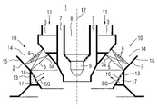
- the premix burner 1 shows a premix burner 1, which is approximately rotationally symmetrical with respect to a burner axis 12.
- One along the burner axis 12 directed pilot burner 9 with a Fuel supply channel 8 and this concentrically enclosing Air supply annular channel 7 is surrounded concentrically from a fuel ring channel 3.
- This fuel ring channel 3 is partially concentrically enclosed by a premixed air channel 2.
- the premix air channel 2 is the annular channel 14th formed, which has an outer channel wall 15.
- a swirl device forms. At least one of these swirl blades 5 is as Hollow blade 5a formed. It points one by several small openings formed inlet 6 for a fuel supply on.
- the hollow blade 5a is for the supply of high calorie fuel 11, e.g. Natural gas or fuel oil, designed.
- the fuel ring channel 3 opens into this hollow blade 5a.
- the premix burner 1 can via the pilot burner 9 as a diffusion burner operate. Usually he is but as Premix burners are used, that is, fuel and air first mixed and then sent to combustion. there the pilot burner 9 serves to maintain a pilot flame, combustion during premix burner operation at a possibly changing fuel-air ratio stabilized.
- combustion air 10 and the high calorific fuel 11 mixed in premix air channel 2 and then fed to the combustion.
- high-calorie fuel 11th from the fuel ring channel 3 in a hollow blade 5a of the Swirl vane wreath 5 and from there over the inlet 6 introduced into the combustion air 10 in the premix air channel 2.
- the premix burner 1 of the invention is beyond optionally also the combustion of a low calorific fuel gas SG, for example, a synthesis gas from a coal gasification process, possible.
- a low calorific fuel gas SG for example, a synthesis gas from a coal gasification process
- the injection device 13 comprises a plurality from inlet openings 16 for the fuel gas SG.
- the inlet openings 16 open into the premix air channel 2.
- the injection device 13 has a gas distribution ring 17, the surrounds the premix air channel 2 radially outward.
- low calorific gas SG fully in the annular channel 14 formed as a premixing air duct second downstream of the swirl device 5 in the distributed combustion air flow 10 is injectable.
- the outer channel wall 15 of Ring channel 14 is here with a variety of holes interspersed with the gas distribution ring 17 in fluid communication stand. In this way is through the gas distribution ring 17 also ensures a distributor function, so that low calorific gas SG with the required Pressure and flow rate provided and by the variety of holes in the outer channel wall 15 of the twisted Combustion air 10 can be mixed.
- it is a particularly homogeneous and uniform one Mixing of combustion air 10 with the low calorie Fuel gas SG reached.
- Fuel gas SG can be supplied for the synthesis gas pre-mixing operation.
- the outer channel wall 15 tapers.
- the premix burner 1 for combustion of a low calorific gas SG is in a combustion chamber of a gas turbine, for example a Ring combustion chamber of a stationary gas turbine used.
- premix burner 1 of the invention is an optional Operation with a synthesis gas from a gasification device or a secondary or substitute fuel possible, since the premix burner 1 designed as a two- or multi-fuel burner is that with both low calorific fuel gas SG as well with high calorie fuel 11, e.g. Natural gas or fuel oil, can be applied.
- high calorie fuel e.g. Natural gas or fuel oil
- Fuel gas SG is the combustion air 10 imparted a twist and the low calorific fuel gas SG in the twisted Combustion air 10 injected and mixed with this. This mixture is then burned. It can also teilverPhynstes low-calorie fuel gas SG in the twisted Combustion air 10 are injected.
- low calorie Fuel gas SG is advantageously a gasifier fossil fuel, especially gasified coal from a Gasification device, used.
- the premix burner 1 is particularly advantageous a synthesis gas operation in a Gas turbine feasible.
- the main advantage of the premix burner according to the invention 1 and the described method for combustion of a low calorific fuel SG is that the proven Premix combustion concept for natural gas and oil (high calorific Fuels) can be taken over unchanged.
- high calorific Fuels high calorific Fuels
- the premix burner 1 is only through an additional fuel passage for low calorie Brenngase SG expands without the constructive implementation a significant influence on conventional operation combustion system with high calorific fuels.
- the proposed construction allows particularly favorable Mixing properties of the low calorific gas SG with the combustion air 10, with a sufficiently large Throughput (volume flow) of synthesis gas SG of the combustion process can be supplied.
Landscapes
- Engineering & Computer Science (AREA)
- Chemical & Material Sciences (AREA)
- Combustion & Propulsion (AREA)
- Mechanical Engineering (AREA)
- General Engineering & Computer Science (AREA)
Abstract
Die Erfindung betrifft einen Vormischbrenner (1) zur Verbrennung
eines niederkalorischen Brenngases (SG), mit einem sich
entlang einer Brennerachse (12) erstreckenden Luftkanal (2)
über den Verbrennungsluft (10) zuführbar ist. In dem Luftkanal
(2) ist eine Dralleinrichtung (5) angeordnet, wodurch der
Verbrennungsluft (10) ein Drall aufprägbar ist. Stromab der
Dralleinrichtung (5) ist eine Eindüseeinrichtung (13) für das
niederkalorische Brenngas (SG) vorgesehen. Die Erfindung betrifft
weiterhin ein Verfahren zur Verbrennung eines niederkalorischen
Brenngases (SG), bei dem Verbrennungsluft (10)
ein Teil aufgeprägt, niederkalorisches Brenngas (SG) in die
verdrallte Verbrennungsluft (10) eingedüst und mit dieser intensiv
vermischt wird, und anschließend das Gemisch verbrannt
wird.

Description
Die Erfindung betrifft einen Vormischbrenner zur Verbrennung eines niederkalorischen Brenngases, insbesondere eines Synthesegases. Die Erfindung betrifft weiterhin ein Verfahren zur Verbrennung eines niederkalorischen Brenngases.The invention relates to a premix burner for combustion a low calorie combustible gas, in particular a synthesis gas. The invention further relates to a method for the combustion of a low calorific fuel gas.
Ein Brenner für gasförmige Brennstoffe, wie er insbesondere in einer Gasturbinenanlage eingesetzt wird, ist beispielsweise aus der DE 42 12 810 A1 bekannt. Hieraus geht hervor, dass Verbrennungsluft durch ein Luft-Ringkanalsystem und Brennstoff durch ein weiteres Ringkanalsystem der Verbrennung zugeführt werden. Dabei wird ein hochkalorischer Brennstoff (Erdgas oder Heizöl) aus dem Brennstoffkanal in den Luftkanal eingedüst, entweder direkt oder aus als Hohlschaufeln ausgebildeten Drallschaufeln.A burner for gaseous fuels, in particular used in a gas turbine plant is, for example known from DE 42 12 810 A1. It can be seen that Combustion air through an air-ring channel system and fuel fed through another annular channel system of combustion become. This is a high-calorie fuel (Natural gas or fuel oil) from the fuel channel into the air duct injected, either directly or formed as a hollow blades Swirl blades.
Damit soll u.a. eine möglichst homogene Mischung von Brennstoff
und Luft erreicht werden, um eine stickoxidarme Verbrennung
zu erzielen. Eine möglichst geringe Stickoxidproduktion
ist aus Gründen des Umweltschutzes und entsprechenden
gesetzlichen Richtlinien für Schadstoffemissionen eine wesentliche
Anforderung an die Verbrennung, insbesondere an die
Verbrennung in der Gasturbinenanlage eines Kraftwerks. Die
Bildung von Stickoxiden erhöht sich exponentiell mit der
Flammentemperatur der Verbrennung. Bei einer inhomogenen Mischung
von Brennstoff und Luft ergibt sich eine bestimmte
Verteilung der Flammentemperaturen im Verbrennungsbereich.
Die Maximaltemperaturen einer solchen Verteilung bestimmen
nach dem genannten exponentiellen Zusammenhang von Stickoxidbildung
und Flammentemperatur maßgeblich die Menge der gebildeten
Stickoxide. Die Verbrennung eines homogenen Brennstoff-Luft-Gemischs
erzielt demnach bei gleicher mittlerer Flammentemperatur
einen niedrigeren Stickoxidausstoß als die
Verbrennung eines inhomogenen Gemisches. Bei der Brennerausführung
in der oben zitierten Druckschrift wird eine räumlich
gute Mischung von Luft und Brennstoff erzielt.
Verglichen mit den klassischen Gasturbinenbrennstoffen Erdgas
und Erdöl, die im Wesentlichen aus Kohlenwasserstoffverbindungen
bestehen, sind die brennbaren Bestandteile von Synthesegas
im Wesentlichen Kohlenmonoxid und Wasserstoff. Zum
wahlweisen Betrieb einer Gasturbine mit Synthesegas aus einer
Vergasungseinrichtung und einem Zweit- oder Ersatzbrennstoff
muss der Brenner in der der Gasturbine zugeordneten Brennkammer
dann als Zwei- oder Mehrbrennstoffbrenner ausgelegt sein,
der sowohl mit dem Synthesegas als auch mit dem Zweitbrennstoff,
z.B. Erdgas oder Heizöl je nach Bedarf beaufschlagt
werden kann. Der jeweilige Brennstoff wird hierbei über eine
Brennstoffpassage im Brenner der Verbrennungszone zugeführt.This is intended, among other things, to achieve the most homogeneous possible mixture of fuel and air, in order to achieve low-NOx combustion. For reasons of environmental protection and corresponding statutory guidelines for pollutant emissions, the lowest possible production of nitrogen oxide is an essential requirement for combustion, in particular combustion in the gas turbine plant of a power plant. The formation of nitrogen oxides increases exponentially with the combustion flame temperature. An inhomogeneous mixture of fuel and air results in a certain distribution of the flame temperatures in the combustion region. The maximum temperatures of such a distribution determined by the said exponential relationship of nitrogen oxide formation and flame temperature significantly the amount of nitrogen oxides formed. The combustion of a homogeneous fuel-air mixture thus achieves a lower nitrogen oxide output at the same average flame temperature than the combustion of an inhomogeneous mixture. In the Brenner version in the above cited document, a spatially good mixture of air and fuel is achieved.
Compared with the traditional gas turbine fuels natural gas and petroleum, which consist essentially of hydrocarbon compounds, the combustible constituents of synthesis gas are essentially carbon monoxide and hydrogen. For selectively operating a gas turbine with syngas from a gasifier and a secondary or substitute fuel, the burner in the gas turbine associated combustion chamber must then be designed as a two- or multi-fuel burner, both with the synthesis gas and with the second fuel, such as natural gas or fuel oil can be applied as needed. The respective fuel is supplied via a fuel passage in the burner of the combustion zone.
Abhängig vom Vergasungsverfahren und Gesamtanlagenkonzept ist
der Heizwert des Synthesegases etwa fünf- bis zehnmal kleiner
verglichen mit dem Heizwert von Erdgas. Hauptbestandteil neben
CO und H2 sind inerte Anteile wie Stickstoff und/oder
Wasserdampf und gegebenenfalls noch Kohlendioxid. Bedingt
durch den kleinen Heizwert müssen demzufolge hohe Volumenströme
an Brenngas durch den Brenner der Brennkammer zugeführt
werden. Dies hat zur Folge, dass für die Verbrennung
von niederkalorische Brennstoffen - wie z.B. Synthesegas eine
oder mehrere gesonderte Brennstoffpassagen zur Verfügung gestellt
werden müssen. Ein derartiger Mehrpassagenbrenner, der
auch für den Synthesegasbetrieb geeignet ist, ist beispielsweise
in der EP 1 227 920 A1 offenbart.Depending on the gasification process and overall plant concept, the calorific value of the synthesis gas is about five to ten times smaller compared to the calorific value of natural gas. Main constituent in addition to CO and H 2 are inert components such as nitrogen and / or water vapor and possibly also carbon dioxide. Due to the low calorific value consequently high volume flows of fuel gas must be supplied through the burner of the combustion chamber. This has the consequence that one or more separate fuel passages must be made available for the combustion of low calorific fuels - such as synthesis gas. Such a multi-pass burner, which is also suitable for synthesis gas operation, is disclosed for example in
Neben der stöchiometrischen Verbrennungstemperatur des Synthesegases ist besonders die Mischungsgüte zwischen Synthesegas und Luft an der Flammenfront eine wesentliche Einflussgröße zur Vermeidung von Temperaturspitzen und somit zur Minimierung der thermischen Stickoxidbildung. In addition to the stoichiometric combustion temperature of the synthesis gas is especially the mixing quality between synthesis gas and air at the flame front is a significant factor to avoid temperature peaks and thus to minimize the thermal nitrogen oxide formation.
Im Hinblick auf zunehmend strengere Anforderungen an den Ausstoß von Stickoxiden gewinnt die Vormischverbrennung auch bei der Verbrennung von niederkalorischen Gasen zunehmend an Bedeutung.In view of increasingly stringent requirements on the output Of nitrogen oxides, premix combustion also gains The combustion of low calorific gases is becoming increasingly important.
Aufgabe der Erfindung ist es daher einen Vormischbrenner zur Verbrennung eines niederkalorischen Brenngases anzugeben. Eine weitere Aufgabe der Erfindung besteht in der Angabe eines Verfahrens zur Verbrennung eines niederkalorischen Brenngases.The object of the invention is therefore a premix burner for Indicate combustion of a low calorific fuel gas. A Another object of the invention is to specify a Process for the combustion of a low calorific fuel gas.
Die erstgenannte Aufgabe wird erfindungsgemäß gelöst durch einen Vormischbrenner zur Verbrennung eines niederkalorischen Brenngases, mit einem sich entlang einer Brennerachse erstreckenden Vormisch-Luftkanal über den Verbrennungsluft zuführbar ist, und mit einer in dem Vormisch-Luftkanal angeordneten Dralleinrichtung, wobei in Strömungsrichtung der Verbrennungsluft stromab der Dralleinrichtung eine Eindüseeinrichtung für das niederkalorische Brenngas angeordnet ist.The first object is achieved by a premix burner for burning a low calorie Fuel gas, with one extending along a burner axis Premix air duct can be supplied via the combustion air is, and arranged with a in the premix air duct Swirling device, wherein in the flow direction of the combustion air downstream of the swirl device an injection device is arranged for the low calorific fuel gas.
Die Erfindung geht von der Überlegung aus, dass zur Sicherstellung eines schadstoffarmen Betriebs die Mischung von Brennstoff und Verbrennungsluft von besonderer Bedeutung ist. Temperaturspitzen können nur durch eine möglichst homogene Mischung vermieden werden. Da bei niederkalorischen Brenngasen hohe Volumenströme an Brenngas involviert sind, die mit Verbrennungsluft zu mischen sind, stellte hier die Lösung der Mischaufgabe die Fachwelt vor besondere Herausforderungen an die konstruktive Auslegung derartiger Brenner.The invention is based on the consideration that to ensure a low-emission operation the mixture of Fuel and combustion air is of particular importance. Temperature peaks can only be as homogeneous as possible Mixture be avoided. As with low calorific fuel gases high volume flows of fuel gas are involved with the Combustion air to mix, here presented the solution of Mixed task presents the experts with special challenges the constructive design of such burner.
Mit dem Synthesegas-Vormischbrenner der Erfindung wird erstmals ein Brennerkonzept vorgeschlagen, welches die Schadstoffausstoß bezogenen Vorteile des Vormischbetriebs auch für niederkalorische Synthesegase als Brennstoff anwendbar macht. Durch die Eindüsevorrichtung stromab der Dralleinrichtung erfolgt die Eindüsung von unverdünnten bzw. teilverdünnten niederkalorischen Brenngas in den bereits verdrallten Massenstrom. Im räumlichen Bereich stromab der Drallvorrichtung erfolgt dadurch eine weitgehend homogene Vermischung des Synthesegases und dem verdrallten Luftmassenstromes. Die Verbrennung des vorgemischten Brenngas-Luftgemisches erfolgt stromab des Brenners bei einer der vorgemischten Luftzahl entsprechenden Temperatur. Zur Stabilisierung der niederkalorischen Vormischflamme kann - speziell im Teillastbereich - ein kleiner Teilmassenstrom des niederkalorischen Brenngases zuvor abgetrennt und im Brennraum über eine im Diffusionsbetrieb betriebene Stützflamme zugeführt werden, z.B. etwa 5% bis 20% des Gesamtvolumenstroms an Brenngas..The synthesis gas premix burner of the invention is used for the first time proposed a burner concept, which pollutant emissions Related advantages of premixing also for low calorie synthesis gas as fuel makes applicable. By the injection device downstream of the twisting device takes place the injection of undiluted or partially diluted low calorie Fuel gas in the already twisted mass flow. In the spatial area downstream of the twisting device takes place thereby a largely homogeneous mixing of the synthesis gas and the twisted air mass flow. The Combustion of the premixed fuel gas-air mixture takes place downstream of the burner at one of the premixed air ratios corresponding temperature. To stabilize the Lower Californian Premix flame can - especially in the partial load range - a small partial mass flow of the low calorie combustible gas previously separated and in the combustion chamber via a in the diffusion mode operated sustaining flame, e.g. about 5% up to 20% of the total volume flow of fuel gas ..
Durch diese Konstruktion mit der Eindüseeinrichtung stromab der Dralleinrichtung sind ausreichend große Volumenströme von niederkalorischen Brenngas mit der Verbrennungsluft mischbar, wobei außerordentlich gute Mischungsergebnisse erzielbar sind. Dies wirkt sich besonders vorteilhaft auf die Schadstoffbilanz des Vormischbrenners aus.By this construction downstream with the injection device the swirl device are sufficiently large volume flows of low calorific fuel gas miscible with the combustion air, where extremely good mixing results can be achieved are. This has a particularly advantageous effect on the pollutant balance from the premix burner.
Weiterhin von Vorteil ist, dass das bewährte Vormischverbrennungskonzept für hochkalorische Brennstoffe wie Erdgas oder Öl unverändert übernommen werden kann, womit eventuelle langwierige Optimierungen und/oder konstruktive Änderungen nicht notwendig sind. D.h., es ist möglich ein herkömmliches Verbrennungssystem, das auf hochkalorische Brennstoffe ausgelegt ist, mittels der an den Luftkanal strömungstechnisch angekoppelten Eindüseeinrichtung durch eine zusätzliche Brennstoffpassage für niederkalorische Brenngase zu erweitern, und zwar ohne das die konstruktive Umsetzung einen nachteiligen Einfluss auf das bestehende konventionelle Verbrennungssystem hätte, z.B. hinsichtlich auftretender Druckverluste.Another advantage is that the proven premix combustion concept for high-calorie fuels such as natural gas or Oil can be taken over unchanged, so that any lengthy Optimizations and / or design changes not necessary. That is, it is possible a conventional combustion system, designed for high calorific fuels is, by means of fluidically coupled to the air duct Injection device through an additional fuel passage for low calorific fuel gases, and indeed without the constructive implementation an adverse effect on the existing conventional combustion system would have, e.g. with regard to occurring pressure losses.
Somit kann der Vormischbrenner sowohl mit dem Synthesegas, das beispielsweise aus Kohle, industriellen Rückständen oder Abfall erzeugt wird, als auch mit einem Zweitbrennstoff, wie z.B. Erdgas oder Öl, betrieben werden. Bei einem Synthesegas-Vormischbetrieb wird lediglich über die Eindüseeinrichtung stromab der Dralleinrichtung der niederkalorische Brennstoff in den Vormisch-Luftkanal eingedüst, wobei in Folge der drallbehafteten Verbrennungsluft eine besonders homogene Mischung sichergestellt ist. Durch dieses Konzept sind auch konstruktive Maßnahmen, die mit zusätzlichen Einbauten einhergehen, vermieden, so dass insbesondere der verdrallte Luftmassenstrom durch eventuelle Einbauten nicht beeinträchtigt wird.Thus, the premix burner with both the synthesis gas, for example, from coal, industrial residues or Waste is generated, as well as with a secondary fuel, such as e.g. Natural gas or oil. For a syngas pre-mixing operation is only via the injection device downstream of the swirl device the low calorific fuel injected into the premix air duct, in consequence of swirling combustion air a particularly homogeneous mixture is ensured. By this concept are too constructive measures associated with additional installations, avoided, so that in particular the twisted Air mass flow not affected by any installations becomes.
Durch den Vormischbrenner erfolgt die Verbrennung entsprechend der eingestellten Luftzahl bei deutlich niedrigeren Temperaturen; was letztendlich zu einer Minimierung der thermischen Stickoxidbildung bei der Verbrennung des niederkalorischen Brenngases führt.The premix burner burns accordingly the set air ratio at much lower temperatures; which ultimately leads to a minimization of the thermal Nitrogen oxide formation during combustion of the low calorie Fuel gas leads.
In besonders vorteilhafter Ausgestaltung weist die Eindüseeinrichtung eine Vielzahl von Einlassöffnungen für Brenngas auf, die in den Vormisch-Luftkanal einmünden.In a particularly advantageous embodiment, the injection device a plurality of fuel gas inlet ports on, which open into the premix air duct.
Vorzugsweise weist die Eindüseeinrichtung einen Gasverteilungsring auf, der den Vormisch-Luftkanal radial auswärts umgibt. Der Vormisch-Luftkanal ist dabei bevorzugt als Ringkanal ausgebildet, der eine äußere Kanalwand aufweist, die mit einer Vielzahl von Bohrungen durchsetzt ist, die mit dem Gasverteilungsring in Strömungsverbindung stehen. Hierdurch wird es erreicht, dass über den vollen Umfang des Ringkanals eine Eindüsung von niederkalorischen Brenngas in die verdrallte Verbrennungsluft gewährleistet ist. Je nach Anforderungen an den Volumenstrom von niederkalorischen Brenngas ist der Durchmesser der Bohrung, deren Anzahl und deren Verteilung an der äußeren Kanalwand entsprechend auszulegen. Durch entsprechende konstruktive Auslegung der Eindüseeinrichtung wird erreicht, dass ein hinreichend großer Brenngas-Volumenstrom eingedüst und damit ein stabiler Synthesegas-Vormischbetrieb sichergestellt ist. Preferably, the injection device has a gas distribution ring which surrounds the premix air passage radially outward. The premix air duct is preferred as an annular channel formed, which has an outer channel wall, with a variety of holes interspersed with the gas distribution ring in fluid communication. This will It achieves that over the full circumference of the ring channel one Injection of low calorific fuel gas into the twisted Combustion air is ensured. Depending on the requirements the volume flow of low calorific fuel gas is the Diameter of the hole, their number and their distribution the outer duct wall should be designed accordingly. By appropriate constructive design of the injection device is achieved that a sufficiently large fuel gas volume flow injected and thus a stable syngas pre-mixing operation is ensured.
In bevorzugter Ausgestaltung verjüngt sich die äußere Kanalwand konusartig in Strömungsrichtung der Verbrennungsluft. Bedingt durch die Eindüsung des niederkalorischen Brenngases durch den in den äußeren Konus eingebrachten Bohrungen kann auf jegliche die Luftströmung negativ beeinflussende zusätzliche Einbauten für die Eindüseeinrichtung verzichtet werden, so dass der Betrieb auch mit konventionellen Brennstoffen (Erdgas oder Heizöl) ohne Einschränkung bei Bedarf weiterhin möglich ist.In a preferred embodiment, the outer channel wall tapers cone-like in the flow direction of the combustion air. Due to the injection of the low calorific fuel gas through the holes introduced into the outer cone to any additional negative influence on the air flow Built-in components for the injection device are dispensed with, allowing the operation even with conventional fuels (Natural gas or fuel oil) without restriction if necessary is possible.
Besonders bevorzugte Ausgestaltung ist der Vormischbrenner in einer Brennkammer, beispielsweise in einer Ringbrennkammer, eingesetzt. Eine derartige Brennkammer ist vorteilhafter Weise als Brennkammer einer Gasturbine ausgestaltet, beispielsweise als eine Ringbrennkammer einer stationären Gasturbine.Particularly preferred embodiment is the premix burner in a combustion chamber, for example in an annular combustion chamber, used. Such a combustion chamber is advantageous designed as a combustion chamber of a gas turbine, for example as an annular combustion chamber of a stationary gas turbine.
Die auf das Verfahren gerichtete Aufgabe wird erfindungsgemäß gelöst durch ein Verfahren zur Verbrennung eines niederkalorischen Brenngases, bei dem Verbrennungsluft ein Drall aufgeprägt, niederkalorisches Brenngas in die verdrallte Verbrennungsluft eingedüst und mit dieser vermischt, und das Gemisch verbrannt wird.The object directed to the method is according to the invention solved by a method of burning a low calorie Fuel gas, in which the combustion air imparted a twist, low calorific fuel gas into the twisted combustion air injected and mixed with this, and the mixture is burned.
Mit diesem Verfahren ist ein besonders homogenes Verbrennungsgemisch erreichbar, wobei hohe Volumenströme an niederkalorischem Brenngas mit der Verbrennungsluft mischbar sind.This process is a particularly homogeneous combustion mixture achievable, with high volume flows of low calorie Fuel gas are miscible with the combustion air.
Hierbei wird vorteilhafter Weise unverdünnte oder teilverdünntes niederkalorisches Brenngas in die verdrallte Verbrennungsluft eingedüst.This is advantageously undiluted or partially diluted low calorific fuel gas into the twisted combustion air injected.
Als niederkalorisches Brenngas kommt ein vergaster fossiler Brennstoff, insbesondere vergaste Kohle, besonders vorteilhaft zum Einsatz. Das Verfahren wird vorzugsweise beim Betrieb eines Gasturbinenbrenners durchgeführt, wobei ein Synthesegas, das einen niederkalorischen Brennstoff darstellt, im Vormischbetrieb verbrannt wird. As low-calorie fuel gas comes a gassing fossil Fuel, especially gasified coal, particularly advantageous for use. The method is preferably in operation a gas turbine burner, wherein a synthesis gas, which is a low calorie fuel, burned in premix operation.
In der Zeichnung ist zur näheren Erläuterung ein Ausführungsbeispiel der Erfindung dargestellt. Es zeigt:
- FIG 1
- ein Längsschnitt durch einen Vormischbrenner gemäß der Erfindung.
- FIG. 1
- a longitudinal section through a premix burner according to the invention.
FIG 1 zeigt einen Vormischbrenner 1, der in etwa rotationssymmetrisch
bezüglich einer Brennerachse 12 ist. Ein entlang
der Brennerachse 12 gerichteter Pilotbrenner 9 mit einem
Brennstoff-Zufuhrkanal 8 und einem diesen konzentrisch umschließenden
Luftzufuhr-Ringkanal 7 ist konzentrisch umgeben
von einem Brennstoff-Ringkanal 3. Dieser Brennstoff-Ringkanal
3 ist teilweise konzentrisch umschlossen von einem Vormisch-Luftkanal
2. Der Vormisch-Luftkanal 2 ist als Ringkanal 14
ausgebildet, der eine äußere Kanalwand 15 aufweist. In diesem
Vormisch-Luftkanal 2 ist ein - schematisch dargestellter -
Kranz von Drallschaufeln 5 eingebaut, der eine Dralleinrichtung
bildet. Mindestens eine dieser Drallschaufeln 5 ist als
Hohlschaufel 5a ausgebildet. Sie weist einen durch mehrere
kleine Öffnungen gebildeten Einlass 6 für eine Brennstoffzuführung
auf. Die Hohlschaufel 5a ist dabei für die Zufuhr von
hochkalorischen Brennstoff 11, z.B. Erdgas oder Heizöl, ausgelegt.
Der Brennstoff-Ringkanal 3 mündet in diese Hohlschaufel
5a.1 shows a
Der Vormischbrenner 1 kann über den Pilotbrenner 9 als Diffusionsbrenner
betrieben werden. Üblicherweise wird er aber als
Vormischbrenner eingesetzt, d.h., Brennstoff und Luft werden
zuerst gemischt und dann der Verbrennung zugeführt. Dabei
dient der Pilotbrenner 9 zur Aufrechterhaltung einer Pilotflamme,
die die Verbrennung während des Vormischbrennerbetriebes
bei einem eventuell wechselnden Brennstoff-Luftverhältnis
stabilisiert.The
Bei der Verbrennung von hochkalorischen Brennstoff 11, d.h.
z.B. Erdgas oder Heizöl, werden Verbrennungsluft 10 und der
hochkalorische Brennstoff 11 im Vormisch-Luftkanal 2 gemischt
und anschließend der Verbrennung zugeführt. Im gezeigten Ausführungsbeispiel
wird dabei der hochkalorische Brennstoff 11
aus dem Brennstoff-Ringkanal 3 in eine Hohlschaufel 5a des
Drallschaufelkranzes 5 geleitet und von dort über den Einlass
6 in die Verbrennungsluft 10 im Vormisch-Luftkanal 2 eingeleitet.In the combustion of
Bei dem Vormischbrenner 1 der Erfindung ist darüber hinaus
wahlweise auch die Verbrennung eines niederkalorischen Brenngases
SG, beispielsweise eines Synthesegases aus einem Kohlevergasungsprozess,
möglich. Hierzu ist in Strömungsrichtung
der Verbrennungsluft 10 stromab von der Dralleinrichtung 5
eine Eindüseeinrichtung 13 für das niederkalorische Brenngas
SG vorgesehen. Die Eindüseeinrichtung 13 umfasst eine Vielzahl
von Einlassöffnungen 16 für das Brenngas SG. Die Einlassöffnungen
16 münden in den Vormisch-Luftkanal 2. Die Eindüseeinrichtung
13 weist einen Gasverteilungsring 17 auf, der
den Vormisch-Luftkanal 2 radial auswärts umgibt. Somit wird
erreicht, dass niederkalorisches Brenngas SG vollumfänglich
in den als Ringkanal 14 ausgebildeten Vormisch-Luftkanal 2
stromab der Dralleinrichtung 5 in den verteilten Verbrennungsluftstrom
10 eindüsbar ist. Die äußere Kanalwand 15 des
Ringkanals 14 ist hierbei mit einer Vielzahl von Bohrungen
durchsetzt, die mit dem Gasverteilungsring 17 in Strömungsverbindung
stehen. Auf diese Weise ist durch den Gasverteilungsring
17 auch eine Verteilerfunktion gewährleistet, so
dass niederkalorisches Brenngas SG mit dem erforderlichen
Druck und Volumenstrom bereitgestellt und durch die Vielzahl
von Bohrungen in der äußeren Kanalwand 15 der verdrallten
Verbrennungsluft 10 zugemischt werden kann. Vorteilhafter
Weise ist hierdurch eine besonders homogene und gleichmäßige
Vermischung von Verbrennungsluft 10 mit den niederkalorischen
Brenngas SG erreicht. Durch entsprechende konstruktive Auslegung
und strömungstechnische Dimensionierung wird erreicht,
dass mittels der Eindüseeinrichtung 13, respektive dem Gasverteilungsring
17, ein hinreichend großer Volumenstrom an
Brenngas SG zuführbar ist für den Synthesegas-Vormischbetrieb.
In Strömungsrichtung der Verbrennungsluft 10
verjüngt sich die äußere Kanalwand 15. Der Vormischbrenner 1
zur Verbrennung eines niederkalorischen Brenngases SG ist in
einer Brennkammer einer Gasturbine, beispielsweise einer
Ringbrennkammer einer stationären Gasturbine einsetzbar.In the
Mit dem Vormischbrenner 1 der Erfindung ist ein wahlweiser
Betrieb mit einem Synthesegas aus einer Vergasungseinrichtung
oder einem Zweit- oder Ersatzbrennstoff möglich, da der Vormischbrenner
1 als Zwei- oder Mehrbrennstoffbrenner ausgelegt
ist, der sowohl mit niederkalorischen Brenngas SG als auch
mit hochkalorischen Brennstoff 11, z.B. Erdgas oder Heizöl,
beaufschlagt werden kann.With the
Bei einem Betrieb des Vormischbrenners 1 mit niederkalorischen
Brenngas SG wird der Verbrennungsluft 10 ein Drall aufgeprägt
und das niederkalorische Brenngas SG in die verdrallte
Verbrennungsluft 10 eingedüst und mit dieser vermischt.
Dieses Gemisch wird anschließend verbrannt. Dabei kann auch
teilverdünntes niederkalorisches Brenngas SG in die verdrallte
Verbrennungsluft 10 eingedüst werden. Als niederkalorisches
Brenngas SG kommt vorteilhafter Weise ein vergaster
fossiler Brennstoff, insbesondere vergaste Kohle aus einer
Vergasungseinrichtung, zum Einsatz. Mit dem Vormischbrenner 1
ist besonders vorteilhaft ein Synthesegasbetrieb bei einer
Gasturbine durchführbar.In an operation of the
Der wesentliche Vorteil des erfindungsgemäßen Vormischbrenners
1 und des beschriebenen Verfahrens zur Verbrennung eines
niederkalorischen Brennstoffs SG besteht darin, dass das bewährte
Vormisch-Verbrennungskonzept für Erdgas und Öl (hochkalorische
Brennstoffe) unverändert übernommen werden kann.
Vorteilhafter Weise sind dabei eventuelle langwierige konstruktive
Brenneroptimierungen und/oder konstruktive Änderungen
nicht erforderlich. Der Vormischbrenner 1 wird lediglich
durch eine zusätzliche Brennstoffpassage für niederkalorische
Brenngase SG erweitert, ohne das die konstruktive Umsetzung
einen nennenswerten Einfluss auf den herkömmlichen Betrieb
des Verbrennungssystems mit hochkalorischen Brennstoffen hat.
Die vorgeschlagene Konstruktion ermöglicht besonders günstige
Mischungseigenschaften des niederkalorischen Brenngases SG
mit der Verbrennungsluft 10, wobei ein hinreichend großer
Durchsatz (Volumenstrom) an Synthesegas SG der Verbrennungsprozess
zugeführt werden kann.The main advantage of the premix burner according to the
Claims (11)
bei dem die Eindüseeinrichtung (13) eine Vielzahl von Einlassöffnungen (16) für Brenngas (B) aufweist, die in den Vormisch-Luftkanal (2) einmünden.Premix burner (10) according to claim 1,
in which the injection device (13) has a multiplicity of fuel gas inlet openings (16) which open into the premixed air channel (2).
bei dem die Eindüseeinrichtung (13) einen Gasverteilungsring (17) aufweist, der den Vormisch-Luftkanal (2) radial auswärts umgibt.Premix burner (10) according to claim 1 or 2,
in which the injection device (13) has a gas distribution ring (17) which surrounds the premixed air channel (2) radially outward.
bei dem der Vormisch-Luftkanal (2) als Ringkanal (14) ausgebildet ist, der eine äußere Kanalwand (15) aufweist, die mit einer Vielzahl von Bohrungen durchsetzt ist, die mit dem Gasverteilungsring (17) in Strömungsverbindung stehen.Premix burner (10) according to claim 1, 2 or 3,
in which the premix air channel (2) is formed as an annular channel (14) having an outer channel wall (15) interspersed with a plurality of bores in fluid communication with the gas distribution ring (17).
bei dem teilverdünntes Brenngas (SG) in die verdrallte Verbrennungsluft (10) eingedüst wird.Method according to claim 8,
in which partially diluted fuel gas (SG) is injected into the twisted combustion air (10).
bei dem als niederkalorisches Brenngas (SG) ein vergaster fossiler Brennstoff, insbesondere vergaste Kohle, eingesetzt wird.Method according to claim 8 or 9,
in which as low calorific fuel gas (SG) a gasified fossil fuel, in particular gasified coal, is used.
Priority Applications (6)
| Application Number | Priority Date | Filing Date | Title |
|---|---|---|---|
| EP04004137A EP1568942A1 (en) | 2004-02-24 | 2004-02-24 | Premix Burner and Method for Combusting a Low-calorific Gas |
| EP05708014A EP1723369B1 (en) | 2004-02-24 | 2005-02-15 | Premix burner and method for combusting a low-calorific gas |
| ES05708014T ES2287902T3 (en) | 2004-02-24 | 2005-02-15 | PREMIX BURNER ASY AS A PROCEDURE FOR THE COMBUSTION OF A POOR FUEL GAS. |
| CN200580005907.6A CN100473905C (en) | 2004-02-24 | 2005-02-15 | Premix burner and method for combusting a low-calorific gas |
| PCT/EP2005/050656 WO2005080878A1 (en) | 2004-02-24 | 2005-02-15 | Premix burner and method for burning a low-calorie combustion gas |
| US10/590,379 US7448218B2 (en) | 2004-02-24 | 2005-02-15 | Premix burner and method for burning a low-calorie combustion gas |
Applications Claiming Priority (1)
| Application Number | Priority Date | Filing Date | Title |
|---|---|---|---|
| EP04004137A EP1568942A1 (en) | 2004-02-24 | 2004-02-24 | Premix Burner and Method for Combusting a Low-calorific Gas |
Publications (1)
| Publication Number | Publication Date |
|---|---|
| EP1568942A1 true EP1568942A1 (en) | 2005-08-31 |
Family
ID=34745867
Family Applications (2)
| Application Number | Title | Priority Date | Filing Date |
|---|---|---|---|
| EP04004137A Withdrawn EP1568942A1 (en) | 2004-02-24 | 2004-02-24 | Premix Burner and Method for Combusting a Low-calorific Gas |
| EP05708014A Expired - Lifetime EP1723369B1 (en) | 2004-02-24 | 2005-02-15 | Premix burner and method for combusting a low-calorific gas |
Family Applications After (1)
| Application Number | Title | Priority Date | Filing Date |
|---|---|---|---|
| EP05708014A Expired - Lifetime EP1723369B1 (en) | 2004-02-24 | 2005-02-15 | Premix burner and method for combusting a low-calorific gas |
Country Status (5)
| Country | Link |
|---|---|
| US (1) | US7448218B2 (en) |
| EP (2) | EP1568942A1 (en) |
| CN (1) | CN100473905C (en) |
| ES (1) | ES2287902T3 (en) |
| WO (1) | WO2005080878A1 (en) |
Cited By (8)
| Publication number | Priority date | Publication date | Assignee | Title |
|---|---|---|---|---|
| EP2042807A1 (en) * | 2007-09-25 | 2009-04-01 | Siemens Aktiengesellschaft | Pre-mix stage for a gas turbine burner |
| WO2009068427A1 (en) * | 2007-11-27 | 2009-06-04 | Alstom Technology Ltd | Device and method for operating a gas turbine system using a second, hydrogen-rich fuel |
| CN101000135B (en) * | 2006-01-09 | 2011-09-07 | 斯奈克玛 | Multimode injection system for a combustion chamber, particularly of a gas turbine |
| EP1909030A3 (en) * | 2006-09-29 | 2013-01-02 | General Electric Company | Methods and apparatus to facilitate decreasing combustor acoustics |
| WO2015150089A1 (en) * | 2014-04-01 | 2015-10-08 | Siemens Aktiengesellschaft | Dual-fuel burner for a gas turbine |
| EP3320268B1 (en) * | 2015-07-06 | 2020-04-29 | Siemens Aktiengesellschaft | Burner for a gas turbine and method for operating the burner |
| CN112325287A (en) * | 2020-11-10 | 2021-02-05 | 华帝股份有限公司 | Gas mixes structure, combustor and mixes gas heater in advance |
| CN119508848A (en) * | 2024-12-03 | 2025-02-25 | 北京航空航天大学 | Dual fuel center staged multi-flame combustion chamber |
Families Citing this family (26)
| Publication number | Priority date | Publication date | Assignee | Title |
|---|---|---|---|---|
| CA2455011C (en) | 2004-01-09 | 2011-04-05 | Suncor Energy Inc. | Bituminous froth inline steam injection processing |
| EP1645805A1 (en) * | 2004-10-11 | 2006-04-12 | Siemens Aktiengesellschaft | burner for fluidic fuels and method for operating such a burner |
| DE102005061486B4 (en) | 2005-12-22 | 2018-07-12 | Ansaldo Energia Switzerland AG | Method for operating a combustion chamber of a gas turbine |
| DE102006051286A1 (en) * | 2006-10-26 | 2008-04-30 | Deutsches Zentrum für Luft- und Raumfahrt e.V. | Combustion device, has combustion chamber with combustion space and air injecting device including multiple nozzles arranged on circular line, where nozzles have openings formed as slotted holes in combustion space |
| JP5115372B2 (en) * | 2008-07-11 | 2013-01-09 | トヨタ自動車株式会社 | Operation control device for gas turbine |
| EP2161502A1 (en) | 2008-09-05 | 2010-03-10 | Siemens Aktiengesellschaft | Pre-mix burner for a low calorie and high calorie fuel |
| EP2312215A1 (en) * | 2008-10-01 | 2011-04-20 | Siemens Aktiengesellschaft | Burner and Method for Operating a Burner |
| US8220272B2 (en) | 2008-12-04 | 2012-07-17 | General Electric Company | Combustor housing for combustion of low-BTU fuel gases and methods of making and using the same |
| US8161751B2 (en) * | 2009-04-30 | 2012-04-24 | General Electric Company | High volume fuel nozzles for a turbine engine |
| EP2270398A1 (en) * | 2009-06-30 | 2011-01-05 | Siemens Aktiengesellschaft | Burner, especially for gas turbines |
| US8683804B2 (en) * | 2009-11-13 | 2014-04-01 | General Electric Company | Premixing apparatus for fuel injection in a turbine engine |
| CN101832556B (en) * | 2010-06-03 | 2012-02-08 | 蓝星化工有限责任公司 | Combustor by utilizing multiple types of mixed gases as fuels |
| ITTO20101093A1 (en) | 2010-12-30 | 2012-07-01 | Ansaldo Energia Spa | BURNER UNIT, PLANT FOR THE PRODUCTION OF GAS-TURBINE ENERGY INCLUDING THE BURNER GROUP AND METHOD TO OPERATE THE BURNER GROUP |
| US9163841B2 (en) * | 2011-09-23 | 2015-10-20 | Siemens Aktiengesellschaft | Cast manifold for dry low NOx gas turbine engine |
| CN102537959B (en) * | 2012-02-28 | 2014-08-27 | 东方电气集团东方锅炉股份有限公司 | Rotational flow and direct current combined gas burner |
| US9127843B2 (en) | 2013-03-12 | 2015-09-08 | Pratt & Whitney Canada Corp. | Combustor for gas turbine engine |
| US9541292B2 (en) | 2013-03-12 | 2017-01-10 | Pratt & Whitney Canada Corp. | Combustor for gas turbine engine |
| US9958161B2 (en) | 2013-03-12 | 2018-05-01 | Pratt & Whitney Canada Corp. | Combustor for gas turbine engine |
| US9228747B2 (en) | 2013-03-12 | 2016-01-05 | Pratt & Whitney Canada Corp. | Combustor for gas turbine engine |
| US9366187B2 (en) | 2013-03-12 | 2016-06-14 | Pratt & Whitney Canada Corp. | Slinger combustor |
| US10240784B2 (en) | 2013-06-17 | 2019-03-26 | Schlumberger Technology Corporation | Burner assembly for flaring low calorific gases |
| JP5980186B2 (en) * | 2013-09-26 | 2016-08-31 | 三菱重工業株式会社 | Burner and coal reforming plant |
| US20150184848A1 (en) * | 2013-12-26 | 2015-07-02 | Rinnai Corporation | Tubular Burner |
| JP6102009B2 (en) | 2015-02-27 | 2017-03-29 | 大陽日酸株式会社 | GAS FUEL BURNER AND HEATING METHOD USING GAS FUEL BURNER |
| CN109237514B (en) * | 2018-08-08 | 2024-02-23 | 中国华能集团有限公司 | Double-pipeline gas fuel burner for gas turbine |
| US11946644B1 (en) * | 2023-03-31 | 2024-04-02 | Solar Turbines Incorporated | Multi-pot swirl injector |
Citations (5)
| Publication number | Priority date | Publication date | Assignee | Title |
|---|---|---|---|---|
| US4761948A (en) * | 1987-04-09 | 1988-08-09 | Solar Turbines Incorporated | Wide range gaseous fuel combustion system for gas turbine engines |
| DE4212810A1 (en) * | 1991-04-25 | 1992-10-29 | Siemens Ag | Burner for liquid or gaseous fuels - has annular air duct which surrounds coaxial ducts for different types of fuel |
| EP0625673A2 (en) * | 1993-05-17 | 1994-11-23 | ABB Management AG | Premixing burner for operating an internal combustion engine, a combustion chamber of a gas turbo group or a combustion plant |
| US5829967A (en) * | 1995-03-24 | 1998-11-03 | Asea Brown Boveri Ag | Combustion chamber with two-stage combustion |
| EP0908671A1 (en) * | 1997-10-08 | 1999-04-14 | Abb Research Ltd. | Combustion process for gaseous, liquid fuels and fuels having medium or low calorific value in a burner |
Family Cites Families (9)
| Publication number | Priority date | Publication date | Assignee | Title |
|---|---|---|---|---|
| US4498288A (en) * | 1978-10-13 | 1985-02-12 | General Electric Company | Fuel injection staged sectoral combustor for burning low-BTU fuel gas |
| DE4409918A1 (en) * | 1994-03-23 | 1995-09-28 | Abb Management Ag | Low calorific value fuel burner for combustion chamber |
| US5680766A (en) * | 1996-01-02 | 1997-10-28 | General Electric Company | Dual fuel mixer for gas turbine combustor |
| US5850732A (en) * | 1997-05-13 | 1998-12-22 | Capstone Turbine Corporation | Low emissions combustion system for a gas turbine engine |
| US6360776B1 (en) * | 2000-11-01 | 2002-03-26 | Rolls-Royce Corporation | Apparatus for premixing in a gas turbine engine |
| EP1277920A1 (en) | 2001-07-19 | 2003-01-22 | Siemens Aktiengesellschaft | Procedure for operating a combuster of a gas-turbine and power plant |
| EP1436546B1 (en) * | 2001-10-19 | 2016-09-14 | General Electric Technology GmbH | Burner for synthesis gas |
| CN2522746Y (en) * | 2002-01-30 | 2002-11-27 | 大庆石油管理局 | Natural-ventilating automatic low-pressure natural gas combustor |
| WO2003098110A1 (en) | 2002-05-16 | 2003-11-27 | Alstom Technology Ltd | Premix burner |
-
2004
- 2004-02-24 EP EP04004137A patent/EP1568942A1/en not_active Withdrawn
-
2005
- 2005-02-15 US US10/590,379 patent/US7448218B2/en not_active Expired - Fee Related
- 2005-02-15 EP EP05708014A patent/EP1723369B1/en not_active Expired - Lifetime
- 2005-02-15 ES ES05708014T patent/ES2287902T3/en not_active Expired - Lifetime
- 2005-02-15 CN CN200580005907.6A patent/CN100473905C/en not_active Expired - Fee Related
- 2005-02-15 WO PCT/EP2005/050656 patent/WO2005080878A1/en not_active Ceased
Patent Citations (6)
| Publication number | Priority date | Publication date | Assignee | Title |
|---|---|---|---|---|
| US4761948A (en) * | 1987-04-09 | 1988-08-09 | Solar Turbines Incorporated | Wide range gaseous fuel combustion system for gas turbine engines |
| DE4212810A1 (en) * | 1991-04-25 | 1992-10-29 | Siemens Ag | Burner for liquid or gaseous fuels - has annular air duct which surrounds coaxial ducts for different types of fuel |
| US5451160A (en) * | 1991-04-25 | 1995-09-19 | Siemens Aktiengesellschaft | Burner configuration, particularly for gas turbines, for the low-pollutant combustion of coal gas and other fuels |
| EP0625673A2 (en) * | 1993-05-17 | 1994-11-23 | ABB Management AG | Premixing burner for operating an internal combustion engine, a combustion chamber of a gas turbo group or a combustion plant |
| US5829967A (en) * | 1995-03-24 | 1998-11-03 | Asea Brown Boveri Ag | Combustion chamber with two-stage combustion |
| EP0908671A1 (en) * | 1997-10-08 | 1999-04-14 | Abb Research Ltd. | Combustion process for gaseous, liquid fuels and fuels having medium or low calorific value in a burner |
Cited By (11)
| Publication number | Priority date | Publication date | Assignee | Title |
|---|---|---|---|---|
| CN101000135B (en) * | 2006-01-09 | 2011-09-07 | 斯奈克玛 | Multimode injection system for a combustion chamber, particularly of a gas turbine |
| EP1909030A3 (en) * | 2006-09-29 | 2013-01-02 | General Electric Company | Methods and apparatus to facilitate decreasing combustor acoustics |
| EP2042807A1 (en) * | 2007-09-25 | 2009-04-01 | Siemens Aktiengesellschaft | Pre-mix stage for a gas turbine burner |
| WO2009040218A1 (en) * | 2007-09-25 | 2009-04-02 | Siemens Aktiengesellschaft | Premix stage for a gas turbine burner |
| WO2009068427A1 (en) * | 2007-11-27 | 2009-06-04 | Alstom Technology Ltd | Device and method for operating a gas turbine system using a second, hydrogen-rich fuel |
| US10208960B2 (en) | 2007-11-27 | 2019-02-19 | Ansaldo Energia Switzerland AG | Method for operating a gas turbine installation and equipment for carrying out the method |
| WO2015150089A1 (en) * | 2014-04-01 | 2015-10-08 | Siemens Aktiengesellschaft | Dual-fuel burner for a gas turbine |
| EP3320268B1 (en) * | 2015-07-06 | 2020-04-29 | Siemens Aktiengesellschaft | Burner for a gas turbine and method for operating the burner |
| US10941940B2 (en) | 2015-07-06 | 2021-03-09 | Siemens Energy Global GmbH & Co. KG | Burner for a gas turbine and method for operating the burner |
| CN112325287A (en) * | 2020-11-10 | 2021-02-05 | 华帝股份有限公司 | Gas mixes structure, combustor and mixes gas heater in advance |
| CN119508848A (en) * | 2024-12-03 | 2025-02-25 | 北京航空航天大学 | Dual fuel center staged multi-flame combustion chamber |
Also Published As
| Publication number | Publication date |
|---|---|
| US20070275337A1 (en) | 2007-11-29 |
| EP1723369A1 (en) | 2006-11-22 |
| CN1922440A (en) | 2007-02-28 |
| ES2287902T3 (en) | 2007-12-16 |
| US7448218B2 (en) | 2008-11-11 |
| WO2005080878A1 (en) | 2005-09-01 |
| EP1723369B1 (en) | 2007-07-18 |
| CN100473905C (en) | 2009-04-01 |
Similar Documents
| Publication | Publication Date | Title |
|---|---|---|
| EP1568942A1 (en) | Premix Burner and Method for Combusting a Low-calorific Gas | |
| EP0710797B1 (en) | Method and device for operating a premix burner | |
| EP2329189B1 (en) | Fuel nozzle | |
| DE3432971C2 (en) | ||
| EP2329196B1 (en) | Burner and method for operating a burner | |
| DE60016345T2 (en) | Premixing chamber for gas turbines | |
| DE102010037412B4 (en) | Dual fuel nozzle for a turbomachine | |
| DE102009025812A1 (en) | Coanda injection system for axially stepped low-emission combustion chambers | |
| DE102008044422A1 (en) | Method and apparatus for the combustion of fuel in a gas turbine | |
| WO2009016079A1 (en) | Premixing burner and method for operating a premixing burner | |
| EP0995066B1 (en) | Arrangement of burners for heating installation, in particular a gas turbine combustion chamber | |
| WO2003036167A1 (en) | Burner for synthesis gas | |
| DE4446842A1 (en) | Method and device for feeding a gaseous fuel into a premix burner | |
| EP1614967B1 (en) | Method and premixed combustion system | |
| CH698098B1 (en) | Premix, combustion chamber and method of operating a combustion chamber. | |
| EP1800062B1 (en) | Burner for combustion of a low-calorific fuel gas and method for operating a burner | |
| EP1800061B1 (en) | Burner for fluidic fuels and method for operating such a burner | |
| EP1754937B1 (en) | Burner head and method of combusting fuel | |
| EP1555484B1 (en) | Process to operate a gas turbine combustor | |
| DE10233161B4 (en) | Burner and pilot burner | |
| CH701905A1 (en) | Method of burning hydrogen-rich, gaseous fuels in a burner and burner for carrying out the method. | |
| EP2703719A1 (en) | Combustion chamber for a gas turbine, gas turbine and method | |
| DE4444125A1 (en) | Process for low-pollution combustion | |
| EP2244015A1 (en) | Pre-mix burner | |
| EP2169308A1 (en) | Fuel supply and method for fuel injection |
Legal Events
| Date | Code | Title | Description |
|---|---|---|---|
| PUAI | Public reference made under article 153(3) epc to a published international application that has entered the european phase |
Free format text: ORIGINAL CODE: 0009012 |
|
| AK | Designated contracting states |
Kind code of ref document: A1 Designated state(s): AT BE BG CH CY CZ DE DK EE ES FI FR GB GR HU IE IT LI LU MC NL PT RO SE SI SK TR |
|
| AX | Request for extension of the european patent |
Extension state: AL LT LV MK |
|
| AKX | Designation fees paid | ||
| STAA | Information on the status of an ep patent application or granted ep patent |
Free format text: STATUS: THE APPLICATION IS DEEMED TO BE WITHDRAWN |
|
| 18D | Application deemed to be withdrawn |
Effective date: 20060301 |
|
| REG | Reference to a national code |
Ref country code: DE Ref legal event code: 8566 |