EP0671672A2 - Appareil à imprimer électrostatographique pour la formation d'images sur une bande - Google Patents
Appareil à imprimer électrostatographique pour la formation d'images sur une bande Download PDFInfo
- Publication number
- EP0671672A2 EP0671672A2 EP95301258A EP95301258A EP0671672A2 EP 0671672 A2 EP0671672 A2 EP 0671672A2 EP 95301258 A EP95301258 A EP 95301258A EP 95301258 A EP95301258 A EP 95301258A EP 0671672 A2 EP0671672 A2 EP 0671672A2
- Authority
- EP
- European Patent Office
- Prior art keywords
- web
- cleaning
- printing
- printer
- rotatable endless
- Prior art date
- Legal status (The legal status is an assumption and is not a legal conclusion. Google has not performed a legal analysis and makes no representation as to the accuracy of the status listed.)
- Withdrawn
Links
Images


Classifications
-
- G—PHYSICS
- G03—PHOTOGRAPHY; CINEMATOGRAPHY; ANALOGOUS TECHNIQUES USING WAVES OTHER THAN OPTICAL WAVES; ELECTROGRAPHY; HOLOGRAPHY
- G03G—ELECTROGRAPHY; ELECTROPHOTOGRAPHY; MAGNETOGRAPHY
- G03G21/00—Arrangements not provided for by groups G03G13/00 - G03G19/00, e.g. cleaning, elimination of residual charge
- G03G21/0005—Arrangements not provided for by groups G03G13/00 - G03G19/00, e.g. cleaning, elimination of residual charge for removing solid developer or debris from the electrographic recording medium
-
- G—PHYSICS
- G03—PHOTOGRAPHY; CINEMATOGRAPHY; ANALOGOUS TECHNIQUES USING WAVES OTHER THAN OPTICAL WAVES; ELECTROGRAPHY; HOLOGRAPHY
- G03G—ELECTROGRAPHY; ELECTROPHOTOGRAPHY; MAGNETOGRAPHY
- G03G21/00—Arrangements not provided for by groups G03G13/00 - G03G19/00, e.g. cleaning, elimination of residual charge
Definitions
- This invention relates to an electrostatographic (for example multi-colour) printer, in particular such a printer as is capable of printing colour images for professional purposes as a cost effective alternative to conventional printing of short to medium sized runs.
- electrostatographic for example multi-colour
- Electrostatographic printing operates according to the principles and embodiments of non-impact printing as described, eg, in "Principles of Non-Impact Printing” by Jerome L Johnson (1986) - Palatino Press - Irvine CA, 92715 USA).
- Electrostatographic printing includes electrographic printing in which an electrostatic charge is deposited image-wise on a dielectric recording member (imaging member) as well as electrophotographic printing in which an overall electrostatically charged photoconductive dielectric recording member is image-wise exposed to conductivity increasing radiation producing thereby a "direct” or “reversal” toner-developable charge pattern on said recording member.
- Direct development is a positive-positive development, and is particularly useful for reproducing pictures and text.
- Reversal is of interest in or when from a negative original a positive reproduction has to be made or vice-versa, or when the exposure derives from an image in digital electrical signal form, wherein the electrical signals modulate a laser beam or the light output of light-emitting diodes (LEDs).
- LEDs light-emitting diodes
- electrostatic also includes the direct image-wise application of electrostatic charges on an insulating support, for example by ionography.
- the surface of the drums may become superficially damaged, resulting in scratches which accumulate compressed toner (a phenomenon known as filmimg and scumming) whereby toner material can not be removed by the cleaning brushes.
- the retained toner material may produce unwanted marks on the printed image.
- a photoreceptor in particular selenium, is pumiced to remove minor defects and scratches.
- the photoreceptor is rotated at a given speed while conventional advanceable toner cleaning web is applied against it under pressure.
- the web is impregnated with a pumicing agent, and automatically pumices the drum until the scratch or defect is removed.
- Refurbishment of a photoconductor surface by removal of a thin stratum thereof acts as a kind of rejuvenation and is in favour of image quality. If during printing, an abrasive cleaning means is engaged with a rotating imaging member, a strong and not easily controllable torque would be applied thereto, with the result that the imaging member would no longer rotate in synchronism with the support material web. In a multi-station printer operating with rotatable imaging drums, this synchronism is essential for avoiding registration problems.
- an electrostatographic printer for forming an image onto a web, which comprises:
- the rotatable endless surface means comprises a belt or the circumferential surface of a drum, especially a belt or drum which has a photoconductive surface.
- imaging member comprises a belt or the circumferential surface of a drum, especially a belt or drum which has a photoconductive surface.
- the printer according to the invention further comprises means for controlling the speed and tension of the web while it is running past the image-producing station.
- adherent contact of the printing web with the drum surface is preferably such that the movement of the printing web controls the peripheral speed of the drum in synchronism with the movement of the printing web.
- the printer is an electrostatographic single-pass multiple station printer, which comprises a plurality of toner image-producing electrostatographic stations each having a drum onto which a toner image can be formed, and means for conveying the web in succession past said stations.
- Drive means such as a drive motor, may be provided to rotationally drive each drum, control means being provided to ensure that, in the printing mode, the movement of the printing web is in synchronism with the peripheral speed of the drums.
- the printer comprises guiding means which determine for the web wrapping angles about the drums, such that adherent contact of said web with each drum is such that the movement of said web controls the peripheral speed of the drums in synchronism with the movement of the web.
- the adherent contact of the web with said rotatable endless surface means is such that the moving web controls the peripheral speed of said surface means, we mean that the only torque, or substantially the only torque, which is applied to said endless surface means is derived from the adherent contact between the web and the endless surface means.
- the endless surface means is constrained to rotate in synchronism with the moving web.
- the adherent contact comes from the transfer means being a corona discharge device providing electrostatic adhesion between the web and the endless surface means.
- said adherent contact results also from a mechanical contact obtained by guiding and tensioning said web over a certain wrapping angle in contact with said rotatable endless surface means.
- the or each toner image-producing electrostatographic station preferably comprises means for charging the surface of the drum, and usually the surface of the drums at all the image-producing stations are charged to the same polarity.
- photoconductors of the organic type it is most convenient to charge the surface of the drums to a negative polarity and to develop the latent image formed thereon in reversal development mode by the use of a negatively charged toner.
- Refurbishment of a photoconductor surface by removal of a thin stratum (e.g. less than 0.1 ⁇ m) on a total thickness of e.g. 18 ⁇ m acts as a kind of rejuvenation and is in favour of image quality. This has been found to be true as both for inorganic as organic photoconductive layers, that may be present in recording materials with active single or dual layers.
- OPC organic photoconductive
- CGL charge generating layer
- CTL charge transporting layer
- the means for image-wise exposing the charged surface of the drum or belt may comprise an array of image-wise modulated light-emitting diodes or take the form of a scanning laser beam.
- the toner will usually be in dry particulate form, but the invention is equally applicable where the toner particles are present as a dispersion in a liquid carrier medium or in a gas medium in the form of an aerosol.
- each image-producing station comprises a driven rotatable magnetic developing brush and a driven rotatable cleaning brush, both in frictional contact with the drum surface.
- the developing brush and the cleaning brush we have found that by arranging for the developing brush and the cleaning brush to rotate in opposite senses, it can be assured that the resultant torque applied by the brushes to the drum surface is at least partly cancelled out.
- the extents of frictional contact of the developing brush and of the cleaning brush with the drum surface are such that the resultant torque transmitted to the drum surface is substantially zero.
- the resultant torque transmitted to the drum surface is substantially zero is meant that any resultant torque acting upon the drum surface is smaller than the torque applied by the web to the drum surface.
- the position and/or the speed of at least one of said brushes relative to the drum surface may be adjustable thereby to adjust the extent of frictional contact between that brush and the drum surface.
- the web is a final support for the toner images and is unwound from a roll, image-fixing means being provided for fixing the transferred images on the web.
- the printer may further comprise a roll stand for unwinding a roll of web to be printed in the printer, and a web cutter for cutting the printed web into sheets.
- the drive means for the web may comprise one or more drive rollers, preferably at least one drive roller being positioned downstream of the image-producing stations and a brake or at least one drive roller being positioned upstream of the image forming stations. The speed of the web through the printer and the tension therein is dependent upon the speed and the torque applied to these drive rollers.
- the web is conveyed through the printer at a speed of from 5 cm/sec to 50 cm/sec and the tension in the web at each image-producing station preferably lies within the range of 0.2 to 2.0 N/cm web width.
- the adherent contact mentioned hereinbefore is obtained at least partly by guiding means, for example freely rotating rollers, positioned to define a wrapping angle with respect to the rotatable surface means, preferably a wrapping angle of from 5° to 30°, preferably from 10° to 20°.
- the guiding means contacts the web on the side thereof opposite to that on which the toner images are transferred.
- the guiding means are preferably guiding rollers but may, for example, alternatively be formed by stationary air-bearings.
- the transfer means is in the form of a corona discharge device which sprays charged particles having a charge opposite to that of the toner particles.
- the supply current fed to the corona discharge device is preferably within the range of 1 to 10 ⁇ A/cm web width, most preferably from 2 to 5 ⁇ A/cm web width, depending upon the paper characteristics and will be positioned at a distance of from 3 mm to 10 mm from the path of the web.
- the drum comprises a photoconductive surface and the image-producing station further comprises:
- the switching means may include means for moving the developing unit away from the drum in the cleaning mode.
- the developing unit may be pivotally or slidingly mounted in the printer.
- the means for moving the developing unit may be automatically or manually actuated.
- Drive means may be provided for rotating the drum in the cleaning mode, optionally at a higher peripheral speed than in the printing mode, these drive means being disengaged in the printing mode.
- These drive means may include a pulley wheel and drive belt assembly, in which movement of the developing unit into the cleaning mode position tensions the drive belt to enable drive to be transferred to the drum while movement of the developing unit into the printing mode position slackens the drive belt thereby disengaging the drive to the drum.
- the cleaning web is a continuation of the printing web.
- the cleaning web may be in the form of a leader tape attached to the printing web.
- the cleaning web may comprise an abrasive surface, constituted for example by an abrasive sheet secured to the cleaning web, by an abrasive coating formed on at least one face of the cleaning web, or by an abrasive strip positioned obliquely across the cleaning web.
- the cleaning web may be provided with an abrasive surface on both faces.
- the printing web itself may be used as the cleaning web.
- the cleaning web is separate from the printing web and the printer further comprises a cleaning web station having cleaning web supply means and cleaning web take-up means, wherein the cleaning step includes moving the cleaning web station towards the drum to bring the cleaning web into contact therewith.
- the cleaning web may contain successive abrasive cleaning materials having a diminishing abrasive character.
- refurbishment can be carried out in successive stages using more abrading material up to relatively smooth polishing material.
- the abrasion can be further controlled by contact pressure between the abrasive material and the toner developed recording surface to be cleaned.
- Abrasive web-type elements particularly suited for refurbishment of photoconductive surfaces contain in a binder layer resin-bonded particulate abrasive substances of an average particle size less than 30 ⁇ m protruding from the surface in such a degree that an average surface roughness (Ra) is less than 7 ⁇ m. Surface roughness is measured with a PERTHOMETER S6P (tradename of Mahr-Perthen, Germany).
- Particularly useful abrasive substances are aluminum oxide, chrome oxide, cerium oxide, silicon carbide and cubic boron nitride, but polishing may proceed with much softer substances such as calcite, having a Mohs hardness of about 3.
- the printer construction according to the invention is particularly advantageous where the printer is a multi-colour printer comprising magenta, cyan, yellow and black printing stations.
- a printer having a supply station 13 in which a roll 14 of web material 12 is housed, in sufficient quantity to print, say, up to 5,000 images.
- the web 12 is conveyed into a tower-like printer housing 44 in which a support column 46 is provided, housing four similar printing stations A to D.
- a further station E is provided in order to optionally print an additional colour, for example a specially customised colour, for example white.
- the printing stations A to E are mounted in a substantially vertical configuration resulting in a reduced footprint of the printer and additionally making servicing easier.
- the column 46 may be mounted against vibrations by means of a platform 48 resting on springs 51.
- the image on the web is fixed by means of the image-fixing station 16 and fed to a cutting station 20 (schematically represented) and a stacker 52 if desired.
- the web 12 is conveyed through the printer by two drive rollers 22a, 22b one positioned between the supply station 13 and the first printing station A and the second positioned between the image-fixing station 16 and the cutting station 20.
- the drive rollers 22a, 22b are driven by controllable motors, 23a, 23b.
- One of the motors 23a, 23b is speed controlled at such a rotational speed as to convey the web through the printer at the required speed, which may for example be about 125 mm/sec.
- the other motor is torque controlled in such a way as to generate, in conjunction with brake 11, a web tension of, for example, about 1 N/cm web width.
- the printing stations i.e. image-producing stations
- A, B, C, D and E are arranged in a substantially vertical configuration, although it is of course possible to arrange the stations in a horizontal or other configuration.
- the web of paper 12 unwound from the supply roller 14 is conveyed in an upwards direction past the printing stations in turn.
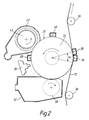
- the moving web 12 is in face-to-face contact with the drum surface 26 over a wrapping angle ⁇ of about 15° (see Figure 2) determined by the position of the guide rollers 36.
- the web of paper 12 passes through the image-fixing station 16, an optional cooling zone (not shown) and thence to the cutting station 20 to cut the web 12 into sheets.
- the web 12 is conveyed through the printer by the motor-driven drive rollers 22a, 22b and tension in the web is generated by the application of the brake 11 acting upon the supply roller 14.
- each printing station comprises a cylindrical drum 24 having a photoconductive outer surface 26.
- a main corotron or scorotron charging device 28 capable of uniformly charging the drum surface 26, for example to a potential of about -600 V
- an exposure station 30 which may, for example, be in the form of a scanning laser beam or an LED array, which will imagewise and line-wise expose the photoconductive drum surface 26 causing the charge on the latter to be selectively reduced, for example to a potential of about -250 V, leaving an image-wise distribution of electric charge to remain on the drum surface 26.
- This so-called "latent image” is rendered visible by a developing unit 32 which by means known in the art will bring a developer in contact with the drum surface 26.
- the developing unit 32 includes a developer brush 33 which is adjustably mounted, enabling it to be moved radially towards or away from the drum 24 for reasons as will be explained further below.
- the developer contains (i) toner particles containing a mixture of a resin, a dye or pigment of the appropriate colour and normally a charge-controlling compound giving triboelectric charge to the toner, and (ii) carrier particles charging the toner particles by frictional contact therewith.
- the carrier particles may be made of a magnetizable material, such as iron or iron oxide.
- the developer brush 33 contains magnets carried within a rotating sleeve causing the mixture of toner and magnetizable material to rotate therewith, to contact the surface 26 of the drum 24 in a brush-like manner.
- Negatively charged toner particles triboelectrically charged to a level of, for example 9 ⁇ C/g, are attracted to the photo-exposed areas on the drum surface 26 by the electric field between these areas and the negatively electrically biased developer so that the latent image becomes visible.
- the toner image adhering to the drum surface 26 is transferred to the moving web 12 by a transfer corona device 34.
- the moving web 12 is in face-to-face contact with the drum surface 26 over a wrapping angle ⁇ of about 15° determined by the position of guide rollers 36.
- the charge sprayed by the transfer corona device being on the opposite side of the web to the drum, and having a polarity opposite in sign to that of the charge on the toner particles, attracts the toner particles away from the drum surface 26 and onto the surface of the web 12.
- the transfer corona device typically has its corona wire positioned about 7 mm from the housing which surrounds it and 7 mm from the paper web.
- a typical transfer corona current is about 3 ⁇ A/cm web width.
- the transfer corona device 34 also serves to generate a strong adherent force between the web 12 and the drum surface 26, causing the latter to be rotated in synchronism with the movement of the web 12 and urging the toner particles into firm contact with the surface of the web 12.
- the web should not tend to wrap around the drum beyond the point dictated by the positioning of a guide roller 36 and there is therefore provided circumferentially beyond the transfer corona device 34 a web discharge corona device 38 driven by alternating current and serving to discharge the web 12 and thereby allow the web to become released from the drum surface 26.
- the web discharge corona device 38 also serves to eliminate sparking as the web leaves the surface 26 of the drum.
- the drum surface 26 is pre-charged to a level of, for example -580 V, by a pre-charging corotron or scorotron device 40.
- the pre-charging makes the final charging by the corona 28 easier.
- any residual toner which might still cling to the drum surface may be more easily removed by a cleaning unit 42 known in the art.
- the cleaning unit 42 includes an adjustably mounted cleaning brush 43, the position of which can be adjusted towards or away from the drum surface 26 to ensure optimum cleaning.
- the cleaning brush 43 is earthed or subject to such a potential with respect to the drum as to attract the residual toner particles away from the drum surface. After cleaning, the drum surface is ready for another recording cycle.
- the web After passing the first printing station A, as described above, the web passes successively to printing stations B, C and D, where images in other colours are transferred to the web. It is critical that the images produced in successive stations be in register with each other. In order to achieve this, the start of the imaging process at each station has to be critically timed. However, accurate registering of the images is possible only if there is no slip between the web 12 and the drum surface 26.
- the electrostatic adherent force between the web and the drum generated by the transfer corona device 34, the wrapping angle ⁇ determined by the relative position of the drum 24 and the guide rollers 36, and the tension in the web generated by the drive rollers 22a, 22b and the braking effect of the brake 11 are such as to ensure that the peripheral speed of the drum 24 is determined substantially only by the movement of the web 12, thereby ensuring that the drum surface moves synchronously with the web.
- the rotatable cleaning brush 43 which is driven to rotate in a sense the same as to that of the drum 24 and at a peripheral speed of, for example twice the peripheral speed of the drum surface.
- the developing unit 32 includes a developer brush 33 which rotates in a sense opposite to that of the drum 24.
- the resultant torque applied to the drum 24 by the rotating developing brush 33 and the counter-rotating cleaning brush 43 is adjusted to be close to zero, thereby ensuring that the only torque applied to the drum is derived from the adherent force between the drum 24 and the web 12. Adjustment of this resultant force is possible by virtue of the adjustable mounting of the cleaning brush 43 and/or the developing brush 33 and the brush characteristics.
- Figure 2A A preferred embodiment of a printing station operating according to the invention is illustrated in Figure 2A which represents a modified embodiment of the printing station represented in the preceding Figure 2.
- Figure 2A illustrates the position during the cleaning mode.
- a cleaning web having abrasive cleaning properties follows the same path as the printing web 12 in the printing mode.
- the cleaning web 210 is coated with or has attached thereto an abrasive layer or an abrasive sheet or ribbon.
- the cleaning web 210 is a continuation of the printing web.
- the photoconductive recording drum 24 is driven rotationally by means of a first drive belt 201 running in the rim of a pulley wheel 202 drivingly connected to the shaft of said drum.
- the same belt 201 runs over an inner pulley wheel 203 of a double pulley assembly, the shaft of which is supported in a ball-bearing from a side wall of the developing unit 32.
- the belt 201 is tensioned by pivoting the developing unit 32 around a pivot point 204.
- the position of the developing unit 32 in the printing mode is shown in dashed lines; the position of the developing unit 32 in the cleaning mode is shown in solid lines.
- the other pulley wheel 209 of the double pulley assembly is driven by a second drive belt 206 which is driven by an electric motor 205 via a motor-shaft mounted drive pulley wheel 207.
- the second drive belt 206 also provides rotational motion to the magnetic developing brush 33 and the cleaning brush 43, coupled to a pulley 211.
- Drive from the pulley wheel 209 passes through a toothed wheel mounted on its shaft engaged with a toothed wheel mounted on the shaft of the magnetic brush (the toothed wheels are not shown in the drawing) to cause the magnetic developing brush 33 to rotate in a sense opposite to the sense of rotation of the cleaning brush 43.
- a guiding roller 208 provides the necessary belt-tension to second drive belt 206.
- the rims of the pulley wheels 202, 203, 207 and 209 are indented and the belts have a toothed structure meshing with the indentation of said rims.
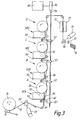
- Figure 3 shows schematically an electrostatographic single-pass multiple station printer containing four printing stations A, B, C and D with which pivotable developing units 32A, 32B, 32C and 32D are associated respectively.
- the position, either printing or cleaning, of each developing unit 32 is switched through a lever mechanism in which a latch lever 60 fixedly united with a swingable lever 61 retains the right hand frame side of developing unit at a centrally located touch point 64.
- the printing stations are again arranged in a substantially vertical configuration.
- the web of paper 12 unwound from the supply roller 14 is conveyed in upwards direction past the printing stations in turn.
- the web 12 is conveyed through the printer by a drive roller 22 driven by a speed motor 23 and tension in the web is controlled by a drive roller 70 connected to a torque motor 71.
- the brake 11 acts upon the supply roller 14 as a torque balancing element.
- the developing units 32A, 32B, 32C and 32D are each pivotally movable around a shaft 50 mounted in a bearing on a frame member (not shown in the drawing) of the printer.
- control means 80 which controls a linear electric motor 56 connected to a common rod 54 with cantilever elements 57 each engaged with a lever mechanism comprising swingable lever 61 and latch lever 60 fixed thereto.
- the latch lever 60 supports the developing unit at a centrally located touch point 64.
- the toner receiving web 12 is unwound from the roll 14 and after transfer of several toner images thereon the toner images are fixed with radiant heat provided by a fixing unit 72. After fixing the toner images the toner receiving web 12 is cut by a cutting means 73 to yield sheets containing the desired image format for receipt in a tray or sheet collector 74.
- the magnetic developing brush 33 no longer makes contact with the drum surface 26.
- the cleaning web 210 carrying an abrasive coating 300 (see Figure 4) or having an abrasive stripe 301 (see Figure 5) adhered on at least one face thereof is moved rapidly in contact with the drum surface 26 using the same driving mechanism as used for moving the printing web 12 in the printing mode.
- the pivoting of the developing unit 32 between the printing mode position and the cleaning mode position may be carried out automatically or manually by the machine operator.
- the web 210 having abrasive properties may be in the form of a leader tape attached to and preceding the beginning of the printing web 12, so that before starting a printing run refurbishment is carried out.
- the leader tape may be attached to the trailing end of the printing web 12.
- the width of the cleaning web may be somewhat larger than the width of the printing web 12.
- any residual toner and a thin stratum of the photoconductive layer 26 of the drum 24 is removed. More particularly by the abrasive treatment toner is removed that has been captured in small scratches of the recording surface and gives unwanted image marks such as lines, spots and smudges in successive prints.
- the peripheral speed of the drum 24 relative to said cleaning web 210 is preferably in the range between 150 to 220 cm/s.
- the cleaning web 210 is advanced from a supply station, for example at a speed of 1.5 cm/s, in order that successive portions of the web engage the drum surface 26. In that way during cleaning a fresh portion of abrasive cleaning web is in engagement with said drum surface.
- the printer comprises a cleaning web station in which a cleaning web 210 is supplied from a supply station including a first spool 400 storing an unused portion of said cleaning web and a receiving station including a second spool 401 for accepting used portions of said web after pressure contact with the surface to be cleaned.
- Said pressure contact is realized in the cleaning mode of the printer by a means of a mechanically retractable spring 403 urging a pressure roller 402 against the smooth rear side of the web 210. That pressure may be obtained likewise pneumatically or by magnetic force (magnetic chuck) bringing the abrasive web 210 into and out of engagement with said rotatable endless surface means.
- the cleaning web station illustrated in Figure 6 may replace the above described pivotable developing unit 32 during its servicing.
Landscapes
- Physics & Mathematics (AREA)
- General Physics & Mathematics (AREA)
- Cleaning In Electrography (AREA)
Priority Applications (1)
| Application Number | Priority Date | Filing Date | Title |
|---|---|---|---|
| EP95301258A EP0671672A3 (fr) | 1994-03-11 | 1995-02-27 | Appareil à imprimer électrostatographique pour la formation d'images sur une bande. |
Applications Claiming Priority (3)
| Application Number | Priority Date | Filing Date | Title |
|---|---|---|---|
| EP94301782 | 1994-03-11 | ||
| EP94301782 | 1994-03-11 | ||
| EP95301258A EP0671672A3 (fr) | 1994-03-11 | 1995-02-27 | Appareil à imprimer électrostatographique pour la formation d'images sur une bande. |
Publications (2)
| Publication Number | Publication Date |
|---|---|
| EP0671672A2 true EP0671672A2 (fr) | 1995-09-13 |
| EP0671672A3 EP0671672A3 (fr) | 1996-04-24 |
Family
ID=26136984
Family Applications (1)
| Application Number | Title | Priority Date | Filing Date |
|---|---|---|---|
| EP95301258A Withdrawn EP0671672A3 (fr) | 1994-03-11 | 1995-02-27 | Appareil à imprimer électrostatographique pour la formation d'images sur une bande. |
Country Status (1)
| Country | Link |
|---|---|
| EP (1) | EP0671672A3 (fr) |
Cited By (2)
| Publication number | Priority date | Publication date | Assignee | Title |
|---|---|---|---|---|
| EP0784248A1 (fr) * | 1996-01-08 | 1997-07-16 | Xeikon Nv | Station de formation d'images électrostatographiques à toner |
| GB2329867A (en) * | 1997-09-23 | 1999-04-07 | Hewlett Packard Co | Cleaning electrophotographic copiers |
Citations (13)
| Publication number | Priority date | Publication date | Assignee | Title |
|---|---|---|---|---|
| US2796367A (en) * | 1955-02-17 | 1957-06-18 | Eugene G Brown | Type cleaning method |
| FR2190060A5 (fr) * | 1972-06-19 | 1974-01-25 | Honeywell Bull | |
| DE7703327U1 (de) * | 1979-02-22 | Siemens Ag, 1000 Berlin Und 8000 Muenchen | Reinigungsvorrichtung | |
| JPS5868778A (ja) * | 1981-10-21 | 1983-04-23 | Fujitsu Ltd | クリ−ニング方法 |
| JPS58209773A (ja) * | 1982-06-01 | 1983-12-06 | Ricoh Co Ltd | 複写機のクリ−ニングシ−ト |
| EP0156510A1 (fr) * | 1984-02-27 | 1985-10-02 | Xerox Corporation | Dispositif pour désencrasser un photo-conducteur |
| JPS6240485A (ja) * | 1985-08-19 | 1987-02-21 | Oki Electric Ind Co Ltd | 静電潜像担持体清掃装置 |
| JPS6240483A (ja) * | 1985-08-19 | 1987-02-21 | Oki Electric Ind Co Ltd | 電子写真記録装置 |
| JPS62297172A (ja) * | 1986-06-17 | 1987-12-24 | Matsushita Electric Ind Co Ltd | 放電記録シ−ト |
| JPH01114883A (ja) * | 1987-10-28 | 1989-05-08 | Mita Ind Co Ltd | 画像形成装置及びこれに用いる用紙 |
| US4977411A (en) * | 1989-11-06 | 1990-12-11 | Xerox Corporation | Electronic color printing system |
| US5147745A (en) * | 1990-10-29 | 1992-09-15 | Eastman Kodak Company | Apparatus for producing raised multiple color images |
| JPH0585636A (ja) * | 1991-09-27 | 1993-04-06 | Sharp Corp | 画像形成装置 |
-
1995
- 1995-02-27 EP EP95301258A patent/EP0671672A3/fr not_active Withdrawn
Patent Citations (13)
| Publication number | Priority date | Publication date | Assignee | Title |
|---|---|---|---|---|
| DE7703327U1 (de) * | 1979-02-22 | Siemens Ag, 1000 Berlin Und 8000 Muenchen | Reinigungsvorrichtung | |
| US2796367A (en) * | 1955-02-17 | 1957-06-18 | Eugene G Brown | Type cleaning method |
| FR2190060A5 (fr) * | 1972-06-19 | 1974-01-25 | Honeywell Bull | |
| JPS5868778A (ja) * | 1981-10-21 | 1983-04-23 | Fujitsu Ltd | クリ−ニング方法 |
| JPS58209773A (ja) * | 1982-06-01 | 1983-12-06 | Ricoh Co Ltd | 複写機のクリ−ニングシ−ト |
| EP0156510A1 (fr) * | 1984-02-27 | 1985-10-02 | Xerox Corporation | Dispositif pour désencrasser un photo-conducteur |
| JPS6240485A (ja) * | 1985-08-19 | 1987-02-21 | Oki Electric Ind Co Ltd | 静電潜像担持体清掃装置 |
| JPS6240483A (ja) * | 1985-08-19 | 1987-02-21 | Oki Electric Ind Co Ltd | 電子写真記録装置 |
| JPS62297172A (ja) * | 1986-06-17 | 1987-12-24 | Matsushita Electric Ind Co Ltd | 放電記録シ−ト |
| JPH01114883A (ja) * | 1987-10-28 | 1989-05-08 | Mita Ind Co Ltd | 画像形成装置及びこれに用いる用紙 |
| US4977411A (en) * | 1989-11-06 | 1990-12-11 | Xerox Corporation | Electronic color printing system |
| US5147745A (en) * | 1990-10-29 | 1992-09-15 | Eastman Kodak Company | Apparatus for producing raised multiple color images |
| JPH0585636A (ja) * | 1991-09-27 | 1993-04-06 | Sharp Corp | 画像形成装置 |
Non-Patent Citations (7)
| Title |
|---|
| PATENT ABSTRACTS OF JAPAN vol. 11 no. 226 (P-598) [2673] ,23 July 1987 & JP-A-62 040483 (OKI ELECTRIC IND.) 21 February 1987, * |
| PATENT ABSTRACTS OF JAPAN vol. 11 no. 226 (P-598) [2673] ,23 July 1987 & JP-A-62 040485 (OKI ELECTRIC IND.) 21 February 1987, * |
| PATENT ABSTRACTS OF JAPAN vol. 12 no. 190 (M-704) [3037] ,3 June 1988 & JP-A-62 297172 (MATSUSHITA ELECTRIC IND.) 24 December 1987, * |
| PATENT ABSTRACTS OF JAPAN vol. 13 no. 355 (P-914) ,9 August 1989 & JP-A-01 114883 (MITA IND.) 8 May 1989, * |
| PATENT ABSTRACTS OF JAPAN vol. 17 no. 417 (M-1457) ,4 August 1993 & JP-A-05 085636 (SHARP) 6 April 1993, * |
| PATENT ABSTRACTS OF JAPAN vol. 7 no. 160 (P-210) [1305] ,14 July 1983 & JP-A-58 068778 (FUJITSU) 23 April 1983, * |
| PATENT ABSTRACTS OF JAPAN vol. 8 no. 60 (P-262) ,22 March 1984 & JP-A-58 209773 (RICOH) 6 December 1983, * |
Cited By (3)
| Publication number | Priority date | Publication date | Assignee | Title |
|---|---|---|---|---|
| EP0784248A1 (fr) * | 1996-01-08 | 1997-07-16 | Xeikon Nv | Station de formation d'images électrostatographiques à toner |
| GB2329867A (en) * | 1997-09-23 | 1999-04-07 | Hewlett Packard Co | Cleaning electrophotographic copiers |
| GB2329867B (en) * | 1997-09-23 | 2001-11-28 | Hewlett Packard Co | Electrophotographic component cleaning apparatus |
Also Published As
| Publication number | Publication date |
|---|---|
| EP0671672A3 (fr) | 1996-04-24 |
Similar Documents
| Publication | Publication Date | Title |
|---|---|---|
| US5455668A (en) | Electrostatographic single-pass multiple-station printer for forming an image on a web | |
| EP0631204B1 (fr) | Imprimante électrostatographique à plusieurs unités et à une passe pour impression rectoverso | |
| US5671475A (en) | Electrostatographic printer for forming an image onto a web and for refurbishing the photosensitive drum | |
| JPH10508390A (ja) | 多機能の電子写真式のプリンタ | |
| US5598255A (en) | Electrostatographic printer for forming a toner image onto a receptor web adapted to reduce smudging | |
| EP0677792B1 (fr) | Appareil de copie ou d'impression électrostatographique | |
| JP2006146216A (ja) | キャリアビードの除去装置 | |
| US6643484B2 (en) | Image forming apparatus including image bearing member rotatable at different peripheral velocities | |
| EP0671672A2 (fr) | Appareil à imprimer électrostatographique pour la formation d'images sur une bande | |
| JPH0887151A (ja) | 画像形成装置 | |
| US6298203B1 (en) | Developing apparatus featuring suppressed deviation of a positional relationship between a developer bearing member and a developer regulator member and method for assembling the apparatus | |
| EP0784248B1 (fr) | Station de formation d'images électrostatographiques à toner | |
| JPH09197935A (ja) | 静電写真方式トナー画像生成ステーション | |
| JPH04174465A (ja) | カラー画像電子写真装置 | |
| JP2789042B2 (ja) | カラー画像形成装置 | |
| EP0671668B1 (fr) | Appareil à imprimer électrostatographique pour la formation d'une image de toner sur un élément de récepteur en forme de bande | |
| JPH112934A (ja) | 画像形成装置 | |
| JP2821771B2 (ja) | カラー画像形成装置 | |
| JP3000520B2 (ja) | カラー画像形成装置 | |
| JP2952497B2 (ja) | カラー画像形成装置 | |
| JP3020102B2 (ja) | カラー画像形成装置 | |
| JP3064829B2 (ja) | 現像装置及びカラー画像形成装置 | |
| JP2759281B2 (ja) | カラー画像形成装置 | |
| JP2784667B2 (ja) | カラー画像形成装置 | |
| JP2000231280A (ja) | 画像形成装置 |
Legal Events
| Date | Code | Title | Description |
|---|---|---|---|
| PUAI | Public reference made under article 153(3) epc to a published international application that has entered the european phase |
Free format text: ORIGINAL CODE: 0009012 |
|
| AK | Designated contracting states |
Kind code of ref document: A2 Designated state(s): AT BE CH DE DK ES FR GB IT LI NL SE |
|
| PUAL | Search report despatched |
Free format text: ORIGINAL CODE: 0009013 |
|
| 17P | Request for examination filed |
Effective date: 19960226 |
|
| AK | Designated contracting states |
Kind code of ref document: A3 Designated state(s): AT BE CH DE DK ES FR GB IT LI NL SE |
|
| 17Q | First examination report despatched |
Effective date: 19970307 |
|
| STAA | Information on the status of an ep patent application or granted ep patent |
Free format text: STATUS: THE APPLICATION IS DEEMED TO BE WITHDRAWN |
|
| 18D | Application deemed to be withdrawn |
Effective date: 19970718 |