EP0665548B1 - Entraínements de disques durs - Google Patents
Entraínements de disques durs Download PDFInfo
- Publication number
- EP0665548B1 EP0665548B1 EP94203758A EP94203758A EP0665548B1 EP 0665548 B1 EP0665548 B1 EP 0665548B1 EP 94203758 A EP94203758 A EP 94203758A EP 94203758 A EP94203758 A EP 94203758A EP 0665548 B1 EP0665548 B1 EP 0665548B1
- Authority
- EP
- European Patent Office
- Prior art keywords
- actuator
- suspension
- head
- signal
- output
- Prior art date
- Legal status (The legal status is an assumption and is not a legal conclusion. Google has not performed a legal analysis and makes no representation as to the accuracy of the status listed.)
- Expired - Lifetime
Links
Images


Classifications
-
- G—PHYSICS
- G11—INFORMATION STORAGE
- G11B—INFORMATION STORAGE BASED ON RELATIVE MOVEMENT BETWEEN RECORD CARRIER AND TRANSDUCER
- G11B21/00—Head arrangements not specific to the method of recording or reproducing
- G11B21/02—Driving or moving of heads
-
- G—PHYSICS
- G11—INFORMATION STORAGE
- G11B—INFORMATION STORAGE BASED ON RELATIVE MOVEMENT BETWEEN RECORD CARRIER AND TRANSDUCER
- G11B19/00—Driving, starting, stopping record carriers not specifically of filamentary or web form, or of supports therefor; Control thereof; Control of operating function ; Driving both disc and head
- G11B19/20—Driving; Starting; Stopping; Control thereof
-
- G—PHYSICS
- G11—INFORMATION STORAGE
- G11B—INFORMATION STORAGE BASED ON RELATIVE MOVEMENT BETWEEN RECORD CARRIER AND TRANSDUCER
- G11B19/00—Driving, starting, stopping record carriers not specifically of filamentary or web form, or of supports therefor; Control thereof; Control of operating function ; Driving both disc and head
- G11B19/02—Control of operating function, e.g. switching from recording to reproducing
- G11B19/04—Arrangements for preventing, inhibiting, or warning against double recording on the same blank or against other recording or reproducing malfunctions
-
- G—PHYSICS
- G11—INFORMATION STORAGE
- G11B—INFORMATION STORAGE BASED ON RELATIVE MOVEMENT BETWEEN RECORD CARRIER AND TRANSDUCER
- G11B21/00—Head arrangements not specific to the method of recording or reproducing
- G11B21/02—Driving or moving of heads
- G11B21/12—Raising and lowering; Back-spacing or forward-spacing along track; Returning to starting position otherwise than during transducing operation
-
- G—PHYSICS
- G11—INFORMATION STORAGE
- G11B—INFORMATION STORAGE BASED ON RELATIVE MOVEMENT BETWEEN RECORD CARRIER AND TRANSDUCER
- G11B21/00—Head arrangements not specific to the method of recording or reproducing
- G11B21/16—Supporting the heads; Supporting the sockets for plug-in heads
- G11B21/20—Supporting the heads; Supporting the sockets for plug-in heads while the head is in operative position but stationary or permitting minor movements to follow irregularities in surface of record carrier
- G11B21/21—Supporting the heads; Supporting the sockets for plug-in heads while the head is in operative position but stationary or permitting minor movements to follow irregularities in surface of record carrier with provision for maintaining desired spacing of head from record carrier, e.g. fluid-dynamic spacing, slider
-
- G—PHYSICS
- G11—INFORMATION STORAGE
- G11B—INFORMATION STORAGE BASED ON RELATIVE MOVEMENT BETWEEN RECORD CARRIER AND TRANSDUCER
- G11B5/00—Recording by magnetisation or demagnetisation of a record carrier; Reproducing by magnetic means; Record carriers therefor
- G11B5/48—Disposition or mounting of heads or head supports relative to record carriers ; arrangements of heads, e.g. for scanning the record carrier to increase the relative speed
- G11B5/4806—Disposition or mounting of heads or head supports relative to record carriers ; arrangements of heads, e.g. for scanning the record carrier to increase the relative speed specially adapted for disk drive assemblies, e.g. assembly prior to operation, hard or flexible disk drives
- G11B5/4833—Structure of the arm assembly, e.g. load beams, flexures, parts of the arm adapted for controlling vertical force on the head
-
- G—PHYSICS
- G11—INFORMATION STORAGE
- G11B—INFORMATION STORAGE BASED ON RELATIVE MOVEMENT BETWEEN RECORD CARRIER AND TRANSDUCER
- G11B5/00—Recording by magnetisation or demagnetisation of a record carrier; Reproducing by magnetic means; Record carriers therefor
- G11B5/48—Disposition or mounting of heads or head supports relative to record carriers ; arrangements of heads, e.g. for scanning the record carrier to increase the relative speed
- G11B5/58—Disposition or mounting of heads or head supports relative to record carriers ; arrangements of heads, e.g. for scanning the record carrier to increase the relative speed with provision for moving the head for the purpose of maintaining alignment of the head relative to the record carrier during transducing operation, e.g. to compensate for surface irregularities of the latter or for track following
- G11B5/60—Fluid-dynamic spacing of heads from record-carriers
- G11B5/6005—Specially adapted for spacing from a rotating disc using a fluid cushion
Definitions
- the present invention relates to hard disk drives and more particularly, but not exclusively, to a method and apparatus for axial control and outside impact resistance of a hard disk drive (HDD).
- HDD hard disk drive
- the trend of the technology for the HDD has recently become high-capacity and light-weight. Therefore, the track pitch and the bit cell of the disk of the HDD has become more minute.
- high-precision technology regarding the control of the servo and the read/write has been devised.
- the technology basically required for this is to maintain the head at a constant minute flying height (less than 0.8 ⁇ m) from the top side of the disk in the overall area of the disk.
- the reason why the head has to be maintained at the minute flying height from the disk is to stabilize signals generated at the time of the read/write operation.
- the stabilization of the signals at the time of the read/write operation is attained when the servomechanism performs the high precision control.
- the constant minute flying height is described by referring to Figure 1- Figure 4.
- a head 161 illustrated in Figure 4 is attached to a gimbal 162 at the end of a suspension 105 attached to a swing arm 103 as illustrated in Figure 1.
- the swing arm 103 makes a rotary motion on a disk centering around a pivot bearing axis 102 through the control of electric current of a voice coil motor VCM and the head 161 becomes able to read or write the data after being transferred to the desired position on a disk 106 as illustrated in Figure 3 according to the rotary motion.
- the head 161 has a constant flying height 163 from the surface of disk 106 as illustrated in Figure 3, for the stabilization of the read/write process.
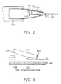
- the head 161, to which transducers 601 and 602 are attached is used to read and write the data from the disk as illustrated in Figure 4 and the main body, to which this can be attached is also referred to as a head slider.
- the head 161 and the head slider can be named as the same depending upon the case.
- the head 161 is attached to a remote end of suspension 105 in the form of a plate spring of stainless steel material, by the gimbal 162, and the suspension 105 is attached to the swing arm 103 as illustrated again in Figure 2.
- Figure 2 shows a case that on the upper and lower sides of one disk 106, two heads 161 are attached to swing arm 103 by gimbals 162 through the suspension 105.
- the head 161 stays safely in the safety area where there is no data on the surface of disk 106 as illustrated in Figure 2, and when the HDD operates, the head 161 is flown to the constant flying height 163 by the rotation air current of the spindle motor spinning disk 106.
- the configuration combining the head 161 and the suspension 105 is referred to as a head gimbals assembly HGA.
- Each head 161 illustrated in Figure 2 is attached to the suspension 105 by an ultrathin plate spring gimbal 162.
- the flying of the heads 161 attached to the gimbals 162 is carried out with a predetermined slope ( ⁇ ) as illustrated in Figure 3.
- a transducer 601 of Figure 4 is located at the trailing edge of the head 161, which writes the signals on the surface of disk 106 and reads the signals from the surface of the disk 106.
- the flying height (hereinafter to as "FH") 163 of the head 161 is the interval between the trailing edge of the head 161 and the surface of disk 106 as illustrated in Figure 3.
- the principle of flying is caused by a dynamic pressure of the air formed between the surface of disk 106 and the surface of the head 161 when the disk 106 rotates.
- the flying surface of the head 161 is referred to as an air bearing surface ABS and the flying begins when the head 161 receives a lifting force after the ABS includes a taper in the air entry portion.
- FIG 4 shows the ABS of the taper flat type head 161 and the thin film inductive type transducer 601. However, one of two transducers 601 and 602 is not used.
- the "owe" patent has installed a pressing member which is engaged with a load beam for the control of the CFH at the head suspension 105 and maintaining the desired CFH with the spring plate and an adjusting screw, but has not provided a way to compensate for the problem of the head 161 colliding with the surface of disk 106.
- a thin leaf, passive damper 165 is attached to the upper part of suspension 105 in order to reduce the displacement amplitude occurring due to the resonant frequency of suspension 105 and the safe arrival of the head 161 as illustrated in Figure 2, but it is difficult to maintain the desired active CFH in accordance with the motion state because the passive damper 165 has no further function than as a passive element.
- preferred embodiments of the present invention aim to provide a method and apparatus which can ensure the stabilization of the read/write signals by continuously enabling the maintenance of a desired constant flying height CFH of a head in both steady and unsteady operation states of an HDD by installing an active element controlling the axial head displacement relative to a spindle motor at a suspension of the HDD.
- Another aim is to provide an apparatus for the improvement of the access time of an HDD by stabilizing the initial settlement of a track following mode as soon as possible with a use of an active damper.
- Still another aim is to provide an apparatus which can replace a head at a track position prior to a seek mode when a flying height FH is confirmed as steady, after first retracking the head in a safety area of a disk during the performance of the read/write operation when an external impact is delivered beyond a certain threshold.
- a method for controlling the separation of a head carried on one end of a flexible suspension of a hard disc drive from the surface of a disk comprising:
- the method comprises:
- the method comprises:
- an apparatus for controlling the separation of a head carried on one end of a flexible suspension of a hard disc drive from the surface of a disk comprising:
- the apparatus comprises:
- the means for generating a control signal comprises:
- the first actuator comprises a piezoelectric polymer attached to the upper side of said suspension.
- the second actuator comprises a piezoelectric ceramic attached to the lower side of said suspension.
- said head is of the taper flat type.
- the embodiments of the invention relate to an impact resistant apparatus and its method by way of an axial control of a hard disk drive continuously maintaining a head at a constant flying height (CFH) under an unsteady state by way of the control of an active element after equipping a head suspension with the active element for the stabilization of signals read/written on a disk.
- CH constant flying height
- FIG. 5 is a block diagram for the maintenance of the CFH of the HDD in accordance with an example of this invention, and it should be noted that the elements the same as and having the same function as those in Figures 1 - 4 in the drawing are represented with the same numbers.
- the minute displacement in accordance with the tension and the compression of the suspension 105 following the FH change of the head 161 is compensated by attaching a first actuator 701 of a piezoelectric ceramic to the upper part of suspension 105 where it is connected with the swing arm 103, and a sensor function to detect the minute displacement is provided in order to maintain the desired CFH between the head 161 and the disk 106 by attaching a second actuator 702 of a piezoelectric polymer to the lower part of the suspension 105 where it is connected to the swing arm 103.
- the output for the compensation of the appropriate displacement of suspension 105 is generated by inputting the compression or tension change detection value of the suspension 105 detected at the second actuator 702 to a suspension control circuit 500.
- the desired CFH can be maintained by applying a compensation value to the first actuator 701.
- the second actuator 702 plays a role similar to a strain gauge, which can detect the state of suspension 105 because an electric current from the power supply of the power source voltage Vcc is changed due to the change of resistance value in accordance with the tension or compression of suspension 105.
- the first and second actuators 701 and 702 of the sensor which are active elements for the control of the axial head displacement relative to the spindle motor should have the characteristics satisfying the following:
- its dynamic disturbance should be of a rapid response; secondly, its maximum control displacement should be less than 0.1 micron (axial); thirdly, its minimum control displacement should be more than 0.1 micron (axial) and fourthly, it should be made of light material not influencing the VCM inertia.
- the attaching locations of the first and second actuators 701 and 702 should be the upper and lower parts of the end of the suspension 105 where it is connected to the swing arm. However, they should be installed very flexibly in the axial direction of the spindle motor and the locations as near to the head 161 as possible should be selected.
- the configuration of the first and second actuators 701 and 702 attached to the suspension 105 should be made in order to function adequately as the sensor detecting the minute change of suspension 105 due to the FH change of the head 161.
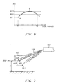
- Figure 6 is a curve diagram of the FH change at the time of using the rotary-type VCM; the horizontal axis represents the radius of the disk and the vertical axis represents the state of the FH change.
- Figure 7 illustrates the state of the suspension 105 and FH changes in accordance with the tension and compression of the first actuator 701 attached to the upper end of suspension 105.
- Figure 8 shows a detailed circuit of the suspension control circuit 500 of the suspension 105 in accordance with this example of the invention, which is comprised of an amplification and signal process circuit 662 outputting the change value of the tension or compression of the suspension 105 detected at the second actuator 702 after the amplification and signal process.
- An error value extraction device extracts an error value [E(s)] after comparing a current FH offset value input into an FH offset terminal 668 and the output value of the amplification and signal process circuit 662.
- a signal truth-delay compensator 663 compensates for the phase delay or the truth of the signals from the output value of the error value extraction device, and an amplifier 661 amplifies the output of the signal truth-delay compensator 663 to provide the amplified output to the first actuator 701.
- Figure 9 is a diagram illustrating another embodiment of the control of suspension 105 in accordance with an example of this invention.
- Figure 8 uses an analog method
- Figure 9 uses a digital method, and is comprised of an A/D converter 667 digitalizing the output signal of the amplification and signal process circuit 662 for the digital process, and an error value extraction part 664 extracting the error value after comparing the FH offset value applied into the FH offset terminal 668 and the output of the A/D converter 667.
- a digital PID controller 669 digitally controls the output of the error value extraction part 664 and generates an adjustment signal after summing up the controlled output in the proper ratio following differentiation and integration, and a D/A converter 670 converts the output of the digital PID controller 669 to provide the converted analog signal to the amplifier 661.
- Figure 10 is a diagram illustrating the concept to solve LQR problems by way of using assumption part 883 after zerorizing the FH offset value through a calculation at the signal process part processing the measurement signal from the first and second actuators 701 and 702 under the reference null position RNP of the head in Figure 8 and Figure 9.
- the piezoelectric ceramic or the piezoelectric polymer used as the first and second actuators 701 and 702 is extended according to its piezoelectric characteristics if an electric field is added, which is a principle generally known, as clarified in page 196 of "Examples and Basis of Application Laser Guide” published by the domestic "Electric and Electronic Research Institute” on September 5, 1985.
- the suspension control circuit 500 amplifies the tensile force detected at the second actuator 702 through amplification and signal process circuit 662.
- the output signal [Y(s)] of the amplification and signal process circuit 662 is subtracted at a subtractor 664 from the FH offset value [R(s)] input to FH offset terminal 668 and the error value [E(s)] is obtained from the subtracted difference value.
- the compensation following the delay or the truth is made by the comparison with the previous signal at the signal delay-truth compensator 663.
- the output of the signal delay-truth compensator 663 is provided to the first actuator 701 of piezoelectric ceramic after amplification at the amplifier 661.
- the first actuator 701 Because of this, the first actuator 701 generates the reverse tensile force in order to return to the RNP as illustrated in Figure 7.
- the sensing part of the second actuator 702 When the FH of the head 161 is decreased as shown by reference numeral "891" of Figure 7, the sensing part of the second actuator 702 generates the compression transformation detection value. If this value is also input to the suspension control circuit 500, the reverse compressive force is applied to the first actuator 701 in order to return to the RNP in the same process way as above.
- the FH change due to the change of suspension 105 as above in case that the rotary-type VCM is used is shown in the same way as the FH change in case that a taper flat type of the head 161 is used as illustrated in the Figure 6.
- the FH change increases in the outside radial direction of disk 106 primarily because the change of the motive pressure occurs in accordance with the difference of the linear velocity of disk 106 on the inner and outer tracks.
- the FH change curve in the same type as Figure 6 is obtained eventually because the bigger skew angle due to the change of the head skew angle between the center-line of the head 161 and the normal line of the track results in the decrease of the FH on the outermost track.
- the read/write signal amplitude of the transducer 601 in Figure 4 is very sensitive to the change of the FH.
- it is essential to maintain the constant flying height CFH of the head 161 on the whole data track. Therefore, the maintenance of the head 161 at the constant flying height CFH from the surface of disk 106 on the whole data section requires a series of developments through the change of the ABS shape of the head 161, i.e. TPC (Transverse Pressure Contours) TAB (Trirail Air Bearing ) and NPAB (Negative Pressure Air Bearing).
- suspension control circuit 500 which is the detection of the tension or compression state of suspension 105 from the first and second actuators 701 and 702 installed at the suspension 105 even in the abnormal operation states of the HDD such as the following:
- the piezoelectric polymer sensor of the second actuator 702 also serves to protect the data by preventing the collision of the head 161 and disk 106 due to external impact.
- This can help to strengthen the impact resistance of the HDD specially in accordance with the miniaturizing trend of the HDD, which can place the head 161 in the safety area without the data on disk 106 beyond a certain impact by installing a sensor for the detection of external acceleration on the PCB and protect the data safely by the impact resistance, like "Safe-Rite HDD" of "Segate Co.” of U.S.A. along with the design of the devices of the HDD.
- the piezoelectric polymer sensor of the second actuator 702 can be used for the same purpose as mentioned above.
- the servo control of this invention can first retract the head 161 performing the read or write into the safety area of the disk and replace the head 161 at the track location prior to a seek mode after the confirmation that the FH is normal.
- the control of the VCM is divided into the seek mode and the track following mode, as well-known in the HDD design:
- the seek mode represents the VCM control mode transferring the head 161 from the currently located track to the track of the target location and the track following mode represents the VCM control mode that the head 161 becomes the read/write function at the center of the track of the target location.
- the radial settling can be improved with the VCM control, but only limited improvement of the axial settling is possible with a passive damper attached to the upper part of suspension 105.
- the access time of the HDD can be improved by stabilizing the initial settling of the track following mode as soon as possible with the active damper according to the piezoelectric ceramic/polymer of the first and second actuators 701 and 702 of this invention.
- the head of the HDD is set to have as constant and low an FH as possible depending upon the upgrade of the capability and the purpose of the high-capacity.
- the pressure distribution in accordance with the fluid current between the ABS (Air Bearing Surface) of the head and the disk, but there is a problem that the start load of the spindle motor increases or that loss of the data results from the increase of the frictional force due to wear because the head and the disk are contacted, in the event that the spindle motor does not rotate at constant velocity at the time of the start or stop.
- this invention can solve the defect due to the contact of the head and the disk by utilizing the actuator of the piezoelectric element from the start of the disk until the rotation of the constant velocity and from the rotation of the constant velocity until the time right after the stop and by separating the head and the disk after applying the power source so that the compressive force can be generated to the actuator attached to the upper part of the suspension.
Claims (9)
- Procédé pour commander la distance séparant une tête (161) portée par une extrémité d'une suspension flexible (105) d'une unité de disque dur, de la surface d'un disque (106), le procédé comprenant:caractérisé en ce que ledit second actionneur (702) est positionné de l'autre côté de la suspension en étant séparé essentiellement par la même distance de ladite tête que l'est ledit premier actionneur (701).la détection de la flexion de la suspension (105) provoquée par une modification dans ladite distance de séparation, au niveau d'un premier actionneur (701) positionné d'un côté de ladite suspension (105) à une certaine distance de ladite tête;la production d'un signal de commande en réponse à ladite flexion détectée; etl'application dudit signal de commande à un second actionneur (702) pour compenser ladite flexion détectée et maintenir ladite distance de séparation;
- Procédé selon la revendication 1, comprenant:l'amplification d'un signal de sortie délivré par le premier actionneur (701) ;le calcul d'une valeur d'erreur à partir de la différence entre le signal de sortie amplifié et une valeur de décalage FH;la compensation du retard ou de la vérité de la valeur d'erreur par détection d'une différence de phase entre la valeur d'erreur et une valeur précédente; etl'amplification du signal d'erreur compensé pour produire ledit signal de commande.
- Procédé selon la revendication 1, comprenant:l'amplification d'un signal de sortie provenant du premier actionneur (701) ;la numérisation du signal de sortie amplifié;l'intégration proportionnelle de la différence entre le signal numérisé et une valeur de décalage FH et la combinaison dans un rapport constant, de la valeur intégrée; etla production dudit signal de commande par conversion sous forme analogique et amplification de la valeur de différence intégrée combinée.
- Dispositif pour commander la distance séparant une tête (161) portée par une extrémité d'une suspension flexible (105) d'une unité de disque dur, de la surface d'un disque, le procédé comprenant:caractérisé en ce que ledit second actionneur (702) est positionné de l'autre côté de la suspension (105) essentiellement à la même distance de ladite tête (101) que ledit premier actionneur (701).un premier actionneur (701) positionné d'un côté de ladite suspension (105) à une certaine distance de ladite tête pour détecter la flexion de la suspension (105) provoquée par un changement dans ladite distance de séparation;un second actionneur (702) situé sur ladite suspension (105) à distance de ladite tête (161);des moyens pour produire un signal de commande en réponse à ladite flexion détectée et pour appliquer ledit signal de commande au second actionneur (702) pour compenser ladite flexion détectée et maintenir ladite distance de séparation;
- Dispositif selon la revendication 4, dans lequel les moyens de production d'un signal de commande comprennent:un circuit d'amplification pour amplifier et délivrer un signal de sortie provenant du premier actionneur (701);des moyens de calcul d'une valeur d'erreur pour calculer une valeur d'erreur à partir de la différence entre le signal de sortie dudit circuit d'amplification et une valeur de décalage FH;un compensateur de vérité-retard du signal pour une compensation de vérité-retard du signal de sortie desdits moyens de calcul de la valeur d'erreur; etun amplificateur pour amplifier le signal de sortie dudit compensateur de vérité-retard du signal pour produire ledit signal de commande.
- Dispositif selon la revendication 4, dans lequel les moyens pour produire le signal de commande comprennent:un circuit d'amplification pour amplifier et délivrer un signal de sortie provenant dudit premier actionneur (701);un convertisseur analogique/numérique (667) pour numériser le signal de sortie dudit amplificateur;des moyens de calcul d'une valeur d'erreur pour calculer une valeur d'erreur à partir de la différence entre le signal de sortie dudit convertisseur analogique/numérique (667) et une valeur de décalage FH;un dispositif de commande PID numérique (669) pour produire un signal d'ajustement à partir du signal de sortie dudit moyen de calcul de la valeur d'erreur;un convertisseur numérique/analogique (670) pour convertir le signal de sortie dudit dispositif de commande PID numérique (669) en un signal analogique; etun second circuit amplificateur pour amplifier le signal de sortie du convertisseur numérique/analogique (670) pour produire ledit signal de commande.
- Dispositif selon l'une quelconque des revendications 4-6, dans lequel ledit premier actionneur (701) comprend un polymère piézoélectrique fixé au côté supérieur de ladite suspension (105).
- Dispositif selon l'une quelconque des revendications 4-7, dans lequel ledit second actionneur (702) comprend une céramique piézoélectrique fixée au côté inférieur de ladite suspension (105).
- Dispositif selon l'une quelconque des revendications 7-8, dans lequel ladite tête (161) est du type plat de forme rétrécie.
Applications Claiming Priority (2)
| Application Number | Priority Date | Filing Date | Title |
|---|---|---|---|
| KR9331792 | 1993-12-31 | ||
| KR1019930031792A KR960016899B1 (ko) | 1993-12-31 | 1993-12-31 | 하드디스크 드라이브 축방향 제어에 의한 외부충격방지장치 및 그 방법 |
Publications (2)
| Publication Number | Publication Date |
|---|---|
| EP0665548A1 EP0665548A1 (fr) | 1995-08-02 |
| EP0665548B1 true EP0665548B1 (fr) | 2001-08-29 |
Family
ID=19374728
Family Applications (1)
| Application Number | Title | Priority Date | Filing Date |
|---|---|---|---|
| EP94203758A Expired - Lifetime EP0665548B1 (fr) | 1993-12-31 | 1994-12-23 | Entraínements de disques durs |
Country Status (5)
| Country | Link |
|---|---|
| US (1) | US6351341B1 (fr) |
| EP (1) | EP0665548B1 (fr) |
| JP (1) | JPH07262726A (fr) |
| KR (1) | KR960016899B1 (fr) |
| DE (1) | DE69428102T2 (fr) |
Families Citing this family (32)
| Publication number | Priority date | Publication date | Assignee | Title |
|---|---|---|---|---|
| KR0135111B1 (ko) * | 1994-09-01 | 1998-04-22 | 김광호 | 헤드 서스팬션의 기록매체 비접촉에 의한 기동-정지 제어방법 및 장치 |
| GB9603508D0 (en) * | 1996-02-20 | 1996-04-17 | Myrica Uk Limited | Improvements in or relating to disk drives |
| KR100255641B1 (ko) * | 1997-07-31 | 2000-05-01 | 윤종용 | 하드디스크 드라이브의 자기헤드 부상 제어방법 및 제어장치 |
| US6667844B1 (en) * | 1998-09-25 | 2003-12-23 | Seagate Technology Llc | Active vibration suppression of glide head suspension arm |
| KR100385327B1 (ko) * | 1999-11-17 | 2003-05-23 | 삼성전자주식회사 | 충격에 강한 하드 디스크 드라이브의 단이 있는액츄에이터 암 |
| EP1143437A1 (fr) | 2000-03-31 | 2001-10-10 | STMicroelectronics S.r.l. | Dispositif de commande de disque dur avec circuits de commande d' actionneur de tête, de moteur d'entraínement de disque et de micropositionneurs de tête piezoelectriques intégrés sur le même substrat |
| US6704157B2 (en) * | 2000-04-14 | 2004-03-09 | Seagate Technology Llc | Passive damping method and circuit for data storage device actuator |
| JP3749081B2 (ja) * | 2000-04-20 | 2006-02-22 | 富士通株式会社 | マイクロアクチュエータを用いたヘッドアセンブリおよび記録媒体駆動装置 |
| US6687081B1 (en) * | 2000-05-15 | 2004-02-03 | Maxtor Corporation | Disk drive using seek profile to enhance fly height control |
| US6791786B2 (en) * | 2000-05-22 | 2004-09-14 | Seagate Technology Llc | Active damping of two-stage actuator system in a disc drive |
| JP2002015537A (ja) * | 2000-06-28 | 2002-01-18 | Matsushita Electric Ind Co Ltd | 浮上ヘッドを用いたディスク装置のためのセンサーシステム |
| US6568252B1 (en) | 2000-07-13 | 2003-05-27 | Seagate Technology Llc | Flyability and glide methodology for 100 GPSI |
| US6975467B1 (en) | 2000-10-11 | 2005-12-13 | Maxtor Corporation | Method and apparatus for high fly write detection in a disk drive |
| JP3706015B2 (ja) * | 2000-11-06 | 2005-10-12 | 株式会社日立グローバルストレージテクノロジーズ | 磁気ディスク装置およびその制御方法 |
| US6717776B2 (en) * | 2001-01-19 | 2004-04-06 | Seagate Technology Llc | Adjustable fly height control using an adjustable head actuator assembly |
| EP1286338A3 (fr) * | 2001-07-26 | 2007-07-11 | Matsushita Electric Industrial Co., Ltd. | Système de fixation d'une tête et disque-dur qui utilise ce système |
| JP3756109B2 (ja) * | 2001-11-28 | 2006-03-15 | 富士通メディアデバイス株式会社 | 磁気ヘッド支持機構及び磁気ヘッド位置決め制御機構 |
| JP3927438B2 (ja) * | 2001-12-06 | 2007-06-06 | 富士通株式会社 | 光学的記憶装置及び光学装置 |
| SG126688A1 (en) * | 2002-01-15 | 2006-11-29 | Inst Data Storage | Active control system and method for reducing diskfluttering induced track misregistrations |
| US6993981B1 (en) | 2002-05-24 | 2006-02-07 | Merlin Technology, Inc. | Tension monitoring arrangement and method |
| EP1482484A3 (fr) * | 2003-05-28 | 2008-05-28 | Matsushita Electric Industrial Co., Ltd. | Dispositif magnétique de soulèvement et d'abaissement d'une tête |
| JP2005158111A (ja) * | 2003-11-21 | 2005-06-16 | Fujitsu Ltd | 加速度センサ、及びこれを用いたディスク装置 |
| JP2006309822A (ja) * | 2005-04-26 | 2006-11-09 | Hitachi Global Storage Technologies Netherlands Bv | 磁気ディスク装置及び記録方法 |
| JP4830521B2 (ja) * | 2006-02-06 | 2011-12-07 | カシオ計算機株式会社 | ハードディスク装置 |
| US7511914B2 (en) * | 2006-03-29 | 2009-03-31 | Maxtor Corporation | Fly height compensation using temperature and non-repeatable runouts |
| JP2007273589A (ja) | 2006-03-30 | 2007-10-18 | Fujitsu Ltd | 薄膜圧電デバイスおよびその作製方法 |
| JP2008181599A (ja) * | 2007-01-25 | 2008-08-07 | Fujitsu Ltd | 磁気ヘッド支持体、磁気ディスク装置およびそれらの製造方法 |
| JP2009032325A (ja) * | 2007-07-26 | 2009-02-12 | Fujitsu Ltd | 記憶装置、制御方法及び制御ユニット |
| JP2009093768A (ja) | 2007-10-11 | 2009-04-30 | Fujitsu Ltd | 記憶装置及び記憶制御回路 |
| JP2009259376A (ja) * | 2008-03-19 | 2009-11-05 | Fujitsu Ltd | 磁気ヘッド及び磁気記録装置及び磁気ヘッドの製造方法 |
| US9171581B2 (en) * | 2013-03-08 | 2015-10-27 | Seagate Technology Llc | Friction force measurement assembly and method |
| US9123371B2 (en) | 2013-10-10 | 2015-09-01 | Seagate Technology Llc | Methods and devices for head-media contact detection |
Family Cites Families (24)
| Publication number | Priority date | Publication date | Assignee | Title |
|---|---|---|---|---|
| JPS5492308A (en) * | 1977-12-29 | 1979-07-21 | Sony Corp | Head tracking device in recorder-reproducer |
| US4188645A (en) * | 1978-11-02 | 1980-02-12 | Burroughs Corporation | Piezoelectric servo for disk drive |
| US4340956A (en) * | 1980-04-10 | 1982-07-20 | Rca Corporation | Minimum tracking force stylus |
| US4950936A (en) * | 1981-03-09 | 1990-08-21 | The United States Of America As Represented By The Secretary Of The Navy | Piezoelectric sandwich polymer transducer |
| US4605977A (en) | 1983-12-14 | 1986-08-12 | Sperry Corporation | Air bearing head displacement sensor and positioner |
| JPS60136073A (ja) * | 1983-12-23 | 1985-07-19 | Hitachi Ltd | 磁気デイスク装置 |
| JPS61148681A (ja) * | 1984-12-22 | 1986-07-07 | Nippon Telegr & Teleph Corp <Ntt> | 浮動ヘツド支持機構 |
| JPS63108576A (ja) * | 1986-10-27 | 1988-05-13 | Nec Corp | 浮動ヘツドのロ−デイング機構 |
| JPH01311481A (ja) * | 1987-10-29 | 1989-12-15 | Sony Corp | 磁気ヘッド装置 |
| EP0342625B1 (fr) | 1988-05-18 | 1994-03-23 | Fujitsu Limited | Mécanisme de suspension de tête pour un appareil d'enregistrement |
| JP2557971B2 (ja) * | 1989-02-14 | 1996-11-27 | インターナショナル・ビジネス・マシーンズ・コーポレーション | データ記憶装置及びヘッドをディスクのランディング部上に位置決めさせる方法 |
| JPH03113879A (ja) | 1989-09-26 | 1991-05-15 | Asahi Optical Co Ltd | ディスク駆動装置 |
| SG47005A1 (en) * | 1990-06-28 | 1998-03-20 | Mitsubishi Electric Corp | Movable head position controlling device for magnetic recording and reproducing apparatuses |
| JP3082929B2 (ja) * | 1990-07-28 | 2000-09-04 | ソニー株式会社 | 記録ディスク駆動装置 |
| NL9001939A (nl) * | 1990-09-04 | 1992-04-01 | Philips Nv | Magneetbandapparaat alsmede aftasteenheid en methode voor het lezen van een informatieblok van een magneetband. |
| JPH04129072A (ja) | 1990-09-18 | 1992-04-30 | Fujitsu Ltd | 磁気ディスク装置 |
| US5313445A (en) * | 1991-03-01 | 1994-05-17 | Sharp Kabushiki Kaisha | Reproducing apparatus with suspension supporting a floating-type head with a bevelled slider |
| JPH0547020A (ja) | 1991-08-09 | 1993-02-26 | Fuji Xerox Co Ltd | 情報記録再生用光デイスク装置 |
| DE69232043T2 (de) * | 1992-02-19 | 2002-03-21 | Tandberg Data Asa Oslo | Verfahren und Vorrichtung zur Positionierung eines Magnetkopfes |
| US5408376A (en) * | 1992-10-06 | 1995-04-18 | Matsushita Electric Industrial Co., Ltd. | Piezoelectric head actuator |
| US5299082A (en) * | 1992-11-10 | 1994-03-29 | Maxtor Corporation | Actuator assembly with compensated outer arms |
| US5377058A (en) * | 1992-12-31 | 1994-12-27 | International Business Machines Corporation | Fly height servo control of read/write head suspension |
| JPH06215433A (ja) * | 1993-01-20 | 1994-08-05 | Mitsubishi Electric Corp | 光磁気ディスク装置 |
| FR2776760B1 (fr) | 1998-03-31 | 2000-05-05 | Air Liquide | Procede et appareil de separation d'air par distillation cryogenique |
-
1993
- 1993-12-31 KR KR1019930031792A patent/KR960016899B1/ko not_active IP Right Cessation
-
1994
- 1994-12-23 DE DE69428102T patent/DE69428102T2/de not_active Expired - Lifetime
- 1994-12-23 EP EP94203758A patent/EP0665548B1/fr not_active Expired - Lifetime
- 1994-12-28 JP JP6326656A patent/JPH07262726A/ja active Pending
- 1994-12-28 US US08/364,972 patent/US6351341B1/en not_active Expired - Lifetime
Also Published As
| Publication number | Publication date |
|---|---|
| US6351341B1 (en) | 2002-02-26 |
| EP0665548A1 (fr) | 1995-08-02 |
| KR960016899B1 (ko) | 1996-12-26 |
| KR950020617A (ko) | 1995-07-24 |
| JPH07262726A (ja) | 1995-10-13 |
| DE69428102D1 (de) | 2001-10-04 |
| DE69428102T2 (de) | 2002-04-11 |
Similar Documents
| Publication | Publication Date | Title |
|---|---|---|
| EP0665548B1 (fr) | Entraínements de disques durs | |
| US5521772A (en) | Disk drive with accerleration rate sensing | |
| US6888694B2 (en) | Active control system and method for reducing disk fluttering induced track misregistrations | |
| US5862015A (en) | Head suspension with resonance feedback transducer | |
| US6538836B1 (en) | Microactuator for fine positioning in a disc drive | |
| US5991114A (en) | Disc drive having gram load reducer and method of operating gram load reducer | |
| US5856896A (en) | Gimbal suspension for supporting a head in a disc drive assembly | |
| US5539592A (en) | System and method for monitoring friction between head and disk to predict head disk interaction failure in direct access storage devices | |
| US6674600B1 (en) | Disk drive having separate motion sensors for base and actuator | |
| US4967293A (en) | Multi-positioner magnetic disk storage apparatus having means for reducing mechanical vibration interference between positioners | |
| EP1643488B1 (fr) | Lecteur de disque | |
| US5299075A (en) | Apparatus and method for shock attenuation in a disk recording and/or reproduction system using variable gain acceleration sensor | |
| US6690545B1 (en) | Air bearing slider including a depressed region extending from a main support structure between a pressurized pad support base and a contact pad support base | |
| US4605977A (en) | Air bearing head displacement sensor and positioner | |
| JP3699882B2 (ja) | ヘッド位置決め装置 | |
| JP3158487B2 (ja) | ヘッド支持機構 | |
| US6600619B1 (en) | Vibration control of piezoelectric microactuator | |
| US6335850B1 (en) | Microactuator for fine positioning in a disc drive | |
| US7375911B1 (en) | Piezoelectric actuator and sensor for disk drive dual-stage servo systems | |
| KR20020013976A (ko) | 적응형 가속도계 피드포워드 서보를 사용하는 디스크드라이브에 대한 방해 배제 | |
| US6697223B2 (en) | Disc head slider with pole tip spacing de-coupled from slider fly height | |
| CN100538825C (zh) | 利用负压槽的低气压空气轴承滑块的系统和方法 | |
| US5734522A (en) | Disc drive system with slider for reading and writing adjacent portions of a zone textured disc | |
| US7092213B1 (en) | Multiple level surface configuration for a sub-ambient pressure air bearing slider | |
| Kartik et al. | Track-following high frequency lateral motion of flexible magnetic media with sub-100 nm positioning error |
Legal Events
| Date | Code | Title | Description |
|---|---|---|---|
| PUAI | Public reference made under article 153(3) epc to a published international application that has entered the european phase |
Free format text: ORIGINAL CODE: 0009012 |
|
| 17P | Request for examination filed |
Effective date: 19941230 |
|
| AK | Designated contracting states |
Kind code of ref document: A1 Designated state(s): DE GB |
|
| 17Q | First examination report despatched |
Effective date: 19980825 |
|
| GRAG | Despatch of communication of intention to grant |
Free format text: ORIGINAL CODE: EPIDOS AGRA |
|
| GRAG | Despatch of communication of intention to grant |
Free format text: ORIGINAL CODE: EPIDOS AGRA |
|
| GRAH | Despatch of communication of intention to grant a patent |
Free format text: ORIGINAL CODE: EPIDOS IGRA |
|
| GRAH | Despatch of communication of intention to grant a patent |
Free format text: ORIGINAL CODE: EPIDOS IGRA |
|
| GRAA | (expected) grant |
Free format text: ORIGINAL CODE: 0009210 |
|
| AK | Designated contracting states |
Kind code of ref document: B1 Designated state(s): DE GB |
|
| REF | Corresponds to: |
Ref document number: 69428102 Country of ref document: DE Date of ref document: 20011004 |
|
| REG | Reference to a national code |
Ref country code: GB Ref legal event code: IF02 |
|
| PLBE | No opposition filed within time limit |
Free format text: ORIGINAL CODE: 0009261 |
|
| STAA | Information on the status of an ep patent application or granted ep patent |
Free format text: STATUS: NO OPPOSITION FILED WITHIN TIME LIMIT |
|
| 26N | No opposition filed | ||
| PGFP | Annual fee paid to national office [announced via postgrant information from national office to epo] |
Ref country code: GB Payment date: 20121227 Year of fee payment: 19 |
|
| PGFP | Annual fee paid to national office [announced via postgrant information from national office to epo] |
Ref country code: DE Payment date: 20121231 Year of fee payment: 19 |
|
| REG | Reference to a national code |
Ref country code: DE Ref legal event code: R119 Ref document number: 69428102 Country of ref document: DE |
|
| GBPC | Gb: european patent ceased through non-payment of renewal fee |
Effective date: 20131223 |
|
| REG | Reference to a national code |
Ref country code: DE Ref legal event code: R119 Ref document number: 69428102 Country of ref document: DE Effective date: 20140701 |
|
| PG25 | Lapsed in a contracting state [announced via postgrant information from national office to epo] |
Ref country code: DE Free format text: LAPSE BECAUSE OF NON-PAYMENT OF DUE FEES Effective date: 20140701 |
|
| PG25 | Lapsed in a contracting state [announced via postgrant information from national office to epo] |
Ref country code: GB Free format text: LAPSE BECAUSE OF NON-PAYMENT OF DUE FEES Effective date: 20131223 |