EP0661395B1 - Oscillating control of a nipper frame in a lap holding mechanism for a comber - Google Patents
Oscillating control of a nipper frame in a lap holding mechanism for a comber Download PDFInfo
- Publication number
- EP0661395B1 EP0661395B1 EP94918567A EP94918567A EP0661395B1 EP 0661395 B1 EP0661395 B1 EP 0661395B1 EP 94918567 A EP94918567 A EP 94918567A EP 94918567 A EP94918567 A EP 94918567A EP 0661395 B1 EP0661395 B1 EP 0661395B1
- Authority
- EP
- European Patent Office
- Prior art keywords
- nipper
- lap
- cushion plate
- frame
- nipper frame
- Prior art date
- Legal status (The legal status is an assumption and is not a legal conclusion. Google has not performed a legal analysis and makes no representation as to the accuracy of the status listed.)
- Expired - Lifetime
Links
- 241000347389 Serranus cabrilla Species 0.000 title claims abstract description 22
- 239000011435 rock Substances 0.000 claims description 18
- 238000013459 approach Methods 0.000 claims description 8
- 239000000835 fiber Substances 0.000 description 7
- 229920000742 Cotton Polymers 0.000 description 6
- 238000000034 method Methods 0.000 description 5
- 238000013461 design Methods 0.000 description 2
- 238000005452 bending Methods 0.000 description 1
- 210000001520 comb Anatomy 0.000 description 1
- 238000007796 conventional method Methods 0.000 description 1
- 125000004122 cyclic group Chemical group 0.000 description 1
- 238000005461 lubrication Methods 0.000 description 1
- 238000012423 maintenance Methods 0.000 description 1
- 238000004519 manufacturing process Methods 0.000 description 1
- 230000002093 peripheral effect Effects 0.000 description 1
- 238000003825 pressing Methods 0.000 description 1
- 230000003252 repetitive effect Effects 0.000 description 1
Images


Classifications
-
- D—TEXTILES; PAPER
- D01—NATURAL OR MAN-MADE THREADS OR FIBRES; SPINNING
- D01G—PRELIMINARY TREATMENT OF FIBRES, e.g. FOR SPINNING
- D01G19/00—Combing machines
- D01G19/06—Details
- D01G19/14—Drawing-off and delivery apparatus
- D01G19/16—Nipper mechanisms
-
- Y—GENERAL TAGGING OF NEW TECHNOLOGICAL DEVELOPMENTS; GENERAL TAGGING OF CROSS-SECTIONAL TECHNOLOGIES SPANNING OVER SEVERAL SECTIONS OF THE IPC; TECHNICAL SUBJECTS COVERED BY FORMER USPC CROSS-REFERENCE ART COLLECTIONS [XRACs] AND DIGESTS
- Y10—TECHNICAL SUBJECTS COVERED BY FORMER USPC
- Y10T—TECHNICAL SUBJECTS COVERED BY FORMER US CLASSIFICATION
- Y10T74/00—Machine element or mechanism
- Y10T74/18—Mechanical movements
- Y10T74/18856—Oscillating to oscillating
-
- Y—GENERAL TAGGING OF NEW TECHNOLOGICAL DEVELOPMENTS; GENERAL TAGGING OF CROSS-SECTIONAL TECHNOLOGIES SPANNING OVER SEVERAL SECTIONS OF THE IPC; TECHNICAL SUBJECTS COVERED BY FORMER USPC CROSS-REFERENCE ART COLLECTIONS [XRACs] AND DIGESTS
- Y10—TECHNICAL SUBJECTS COVERED BY FORMER USPC
- Y10T—TECHNICAL SUBJECTS COVERED BY FORMER US CLASSIFICATION
- Y10T74/00—Machine element or mechanism
- Y10T74/18—Mechanical movements
- Y10T74/18888—Reciprocating to or from oscillating
- Y10T74/1892—Lever and slide
- Y10T74/18952—Lever and slide toggle transmissions
Definitions
- the present invention relates to a lap nipping mechanism in a comber which produces a thin sheet composed of fibers, so-called “fleece”, by removing short fibers from a group of fibers, so-called “lap”, in the manufacturing process of cotton yarn.
- the present invention relates to control of the rocking operation of a nipper frame in the lap nipping mechanism, the nipper frame having a cushion plate for use in nipping a lap.
- the average length of cotton fiber depends on its kind or its place of origin. Additionally, even in the same kind of cotton, its average fiber length is not constant and often varies. To produce high-grade cotton yarn with superior tenacity and appearance, it is necessary to remove short cotton fibers (including foreign matter such as nep). Use of a comber is an effective way to attain this objective.
- a comber comprises a combing cylinder, a top comb, a pair of detaching rollers, and a nipper apparatus.
- the nipper apparatus rocks back and forth while nipping sheet-like fibers, so-called "lap", supplied thereto.
- the combing cylinder has a series of needles (i.e., cylinder needles) embedded on its peripheral surface (i.e., cylinder half lap). As the nipper apparatus moves backward, the needles comb the forward end of the lap. This action is called “combing”. This combing action removes short fibers from the lap, producing a thin sheet-like fiber product, so-called “fleece”.
- the fleece is transferred forward as the nipper apparatus moves forward (towards the detaching rollers).
- the detaching rollers rotate in reverse and cause a preceding fleece, previously combed, to move rearward.
- the rear end of the preceding fleece is overlapped with the front end of a newly combed fleece (i.e., succeeding fleece).
- the detaching rollers rotate in the forward direction of rotation, to pull out forward the pieced together fleeces. This action is called "piecing".
- the top comb combs the rear end of the succeeding fleece. In the combing process, these operations are repeated to effectively remove the short cotton fibers from the lap.
- the nipper apparatus comprises a nipper frame, a cushion plate fixed on the nipper frame at its front end, and a nipper knife to nip the lap in cooperation with the cushion plate.
- the nipper knife nips the lap at the tip of the cushion plate.
- the nipper frame can rock between a backmost position where the tip of the cushion plate is proximate to the cylinder needles and a foremost position where the tip is proximate to the detaching rollers.
- Methods of rocking the nipper frame in a comber are roughly classified into the following three types according to a path drawn by the tip of the cushion plate.
- the type 3 apparatus is a compromise between the type 1 and 2 apparatuses. This design, however, caused insufficient combing and piecing operations. According to the type 3 design, the tip of the cushion plate approaches the cylinder needles at a position just over the cylinder circle. This increases the rocking stroke of the nipper frame.
- Japanese Unexamined Patent Publication No. 54-6926 discloses a method for controlling the rocking of the nipper frame as described below.
- a total path along which the tip of the cushion plate together with the nipper frame rocks there exists a point where the cushion plate tip nips a lap in cooperation with the nipper knife and releases the lap.
- the nip/release point is hereinafter referred to as "nipper opening/closing position”. Its total path is divided into two sections: a front section between the foremost position and the nipper opening/closing position; and a rear section between the nipper opening/closing position and the backmost position.
- the cushion plate tip moves along an upward projecting arc path in proximity to the cylinder circle.
- the cushion plate tip moves upward along an inclined path coupled to the front end of the arc path in the rear section.
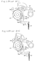
- a nipper frame 32 is rocked by a four-node link mechanism comprising a rocking lever 31, the nipper frame 32 and a following lever 33, as shown in Figs. 5 and 6.
- a pivot 34 of the following lever 33 connected to the front portion of the nipper frame 32 is displaced.
- the following lever 33 is in a two-link structure comprising a first link 35 and a second link 36.
- the second link 36 forming the base portion of the following lever 33, is pressed against a stopper 38 by the action of a spring 37.
- the first and second links 35 and 36 pivot together as a unit about the pivot 36a.
- This pivoting motion causes the tip of the cushion plate 40 to move upward along an inclined path connecting the front point of the upward projecting arc path and a "nip position" where detaching rollers 39 nip a succeeding fleece therebetween.
- the second link 36 supporting the nipper frame 32 repeatedly comes in contact with and moves away from the stopper 38, as the nipper frame 32 rocks.
- This repetitive action causes the second link 36 and the stopper 38 to wear off and generates noise and vibration.
- the noise and vibrations become more remarkable as the machine runs at higher speeds.
- the nipper frame 32 cannot rock along the predetermined path.
- a lap nipping mechanism according to the pre-characterizing clause of Claim 1 is disclosed in Japanese Unexamined Patent Publication No. 54-11335, wherein the cushion plate tip is disposed in the rear section and reciprocates along a path similar to the path disclosed in Japanese Unexamined Patent Publication No. 54-6926, as the nipper frame rocks.
- the cushion plate tip performs its cyclic motion along a predetermined path in the front section, so that the cushion plate tip goes upward along an inclined path toward the foremost position from the nipper opening/closing position, turns to the horizontal or downward direction to approach the nip position, and then returns downward along an inclined path to the nipper opening/closing position.
- nipper apparatus comprises (as shown in Figs. 7 and 8) a four-node link mechanism made up of a rocking lever 31, a nipper frame 32, a following lever 43, and a rocking arm 44.
- the following lever 43 has a first end (upper end) linked to the nipper frame 32 at its forward portion, and a second end (lower end) linked to the rocking arm 44 which rocks up and down through a cam 46 fixed on a cylinder shaft 45.
- a pivot 43a is displaced up and down, and the tip of the cushion plate 40 rocks along the aforementioned predetermined path.
- This nipper apparatus not only requires lubrication for maintenance and tends to increase vibrations of the machine frame, when adapted to a high-speed comber but also has the disadvantage that lint is apt to be caught between the cam 46 and the cam roller 47 of the rocking arm 44. If lint is caught, the nipper frame 32 is prevented from rocking along a predetermined path. Also, using the cam 46 requires troublesome adjustments and its screws tend to loosen.
- an improved lap nipping mechanism for a comber which comprises a pair of detaching rollers for feeding a fleece forward and backward, a combing cylinder for combing a supplied lap to make a succeeding fleece, and a top comb for combing the rear end of the succeeding fleece, wherein the comber pieces together a preceding fleece which when nipped between the pair of detaching rollers is fed forward, wherein the mechanism comprises: a nipper frame, disposed above the combing cylinder, to be rocked back and forth; a cushion plate mounted on said nipper frame at a distal end portion thereof; a cushion plate mounted on said nipper frame at a distal end portion thereof; a nipper member which repeatedly approaches and moves away from said cushion plate, in response to the rocking action of the nipper frame, and which nips the lap in cooperation with the cushion plate; a nipper
- the stationary pivots are disposed above and below the nipper frame, respectively, wherein the upper stationary pivot is located behind the lower stationary pivot and the disposition of the stationary pivot is so that the rocking movement of the nipper frame is such that the tip of the cushion plate moves along an upward projecting arc in a rear section of the predetermined rocking section, where the cushion plate tip moves in proximity to the combing cylinder while nipping the lap in cooperation with the nipper member, and the tip of the cushion plate moves along a downward projecting arc in a front section of the predetermined rocking section where the tip of the cushion plate approaches the pair of detaching roller with releasing the lap which was nipped in cooperation with the nipper member.
- the cushion plate tip moves while maintaining a constant clearance between the tip and the cylinder circle. This lengthens the time of combing the lap to implement effective combing.
- the cushion plate tip moves along a downward projecting arc in the path section between the foremost positon of the rocking stroke and a position where the cushion plate tip is in close proximity to the combing cylinder. Hence, the cushion plate tip reaches a height at which the detaching rollers nip the fleece. Accordingly, the front end portion of the succeeding fleece will not bend when the preceding and succeeding fleeces are pieced together. This implements good piecing action.
- the drive mechanism of the nipper frame does not employ a conventional multistage link using a cam mechanism or a stopper therewith, consequently, the generation of noise and vibrations can be suppressed, and the catching of lint can be prevented. This makes it possible to obtain a comber suitable for a high-speed machine.
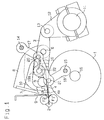
- a pair of detaching rollers 2 are disposed to be adjacent in a vertical direction at the upper front of a combing cylinder 1.
- the detaching rollers 2 feed fleeces Fl and F2 forward and backward.
- a nipper frame 3 is provided above the combing cylinder 1.
- a cushion plate 4 is fixed on the nipper frame 3 at the front end portion thereof.
- a feed roller 5 is rotatably provided above the cushion plate 4.
- a lap feeding source (not illustrated) feeds a lap Lp between the feed roller 5 and the cushion plate 4. As a result of an intermittent rotation of the feed roller 5, the lap Lp required for one cycle of combing is fed near the tip 4a of the cushion plate 4.
- a nipper arm pin 6 is attached to the nipper frame 3 at a center portion thereof, and a nipper arm 8 is pivotably supported on the nipper arm pin 6.
- a nipper knife 7 is fixed on the nipper arm 8 at a forward end thereof. The nipper 7 is moved up and down by means of a well-known mechanism (not illustrated), at a predetermined timing in synchronism with the forward and backward rocking motion of the nipper frame 3.
- a top comb 9 is fixed ahead of the cushion plate 4 by an unillustrated mechanism. The top comb 9 carries out a predetermined motion in synchronism with the nipper frame 3.
- a pressure plate nipper 10 is pivotably supported on the nipper arm pin 6.
- the pressure plate nipper 10 is operated by means of a well-known drive mechanism (not shown) at a predetermined timing, in accordance with the rocking of the nipper frame 3, to nip the lap by pressing it against the cushion plate 4 when the rear end portion of the combed lap is being combed by the top comb 9.
- a nipper shaft 11 is provided behind the combing cylinder 1 and below the nipper frame 3, such that the nipper shaft 11 is pivotable in a forward and reverse directions.
- the base end of a nipper frame driving arm 12 is fixed on the nipper shaft 11 to allow the joint pivoting of the nipper shaft and the nipper frame driving arm.
- a pivot 13 is fixed on the distal end of the arm 12. The rear end portion of the nipper frame 3 is pivotably supported on the pivot 13.
- Pivots 14 and 15, as stationary pivots of a four-node link mechanism, are provided above and below the nipper frame 3, respectively, on the machine frame (not shown) and beside the nipper frame 3.
- the pivots 14 and 15 are in parallel with the pivot 13.
- the lower pivot 15 is located above a cylinder shaft 16.
- the upper pivot 14 is located to the rear of the lower pivot 15, and ahead of the position of the pivot 13 when the nipper frame 3 is in its foremost position of its rocking stroke, as shown in Fig. 1.
- First ends (i.e., proximal ends) of the first and second rocking levers 17 and 18 are pivotably supported on the pivots 14 and 15, respectively.
- Second ends (i.e., distal ends) of the rocking levers 17 and 18 are linked to both ends of a following lever 19 through movable pivots 20 and 21.
- the rocking levers 17 and 18, the following lever 19 as a connector, the stationary pivots 14 and 15, and the movable pivots 20 and 21 form the four-node link mechanism.
- a boss 19a is formed on the following lever 19 at an upper center portion thereof, while a hole 19b is formed in the boss 19a.
- the nipper frame 3 is pivotably connected to the following lever 19 via a connecting shaft 22 which fits into the hole 19b and into another hole (not shown) formed in the front end portion of the nipper frame 3.
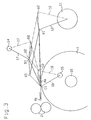
- the distance between the stationary pivot 14 and the movable pivot 20 in the rocking lever 17 is equal to the distance between the stationary pivot 15 and the movable pivot 21 in the rocking lever 18.
- first rocking lever 17 rocks, its second end describes a downward projecting arc (hereinafter referred to as “downward convex arc”) beside the nipper frame 3.
- second rocking lever 18 rocks, its second end describes an upward projecting arc (hereinafter referred to as "upward convex arc”) beside the cushion plate 4.
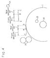
- the tip 4a of the cushion plate 4 fixed on the nipper frame 3 moves along a smooth curve (L-M-N) as shown in Fig. 4.
- position M indicates a position of the nipper end 4a where the nipper end 4a nips and releases the lap Lp in cooperation with the nipper knife 7, i.e., a nipper opening/closing position.
- Position N indicates the backmost position of a rocking stroke of the nipper end 4a
- position L indicates the foremost position of a rocking stroke of the nipper end 4a.
- the nipper end 4a reciprocates across a section between position N and position L.
- a rear section E2 i.e., a section between positions M and N in the total reciprocating path
- the lap Lp is nipped between the nipper knife 7 and the nipper end 4a and undergoes combing by needle segments (not shown) of the combing cylinder 1.
- the connecting shaft 22 is in its rear section E2
- the shaft 22 moves along an upward convex arc.
- the nipper end 4a is in the rear section E2
- the nipper end 4a describes an upward convex arc along a cylinder circle.
- the nipper frame 3 reaches the backmost position of its rocking stroke, and thereafter resumes moving forward.
- the connecting shaft 22 moves from position C toward position B
- the nipper end 4a moves forward from the backmost position N to the position M.
- the nipper end 4a also describes an upward convex arc (N-M) along the cylinder circle in the same manner as mentioned above. Combing is also carried out while the nipper end 4a moves from position N to position M.
- the nipper end 4a when the nipper end 4a rocks backward toward the backmost position N and also when the nipper end rocks forward from the backmost position N toward position M, the nipper end is in close proximity to the cylinder circle and moves along an upward convex arc in parallel with the cylinder circle. Accordingly, while the lap Lp undergoes combing, the nipper end 4a moves maintaining a certain clearance between the nipper end and the cylinder circle. This lengthens the time of combing the lap Lp to allow for effective combing.
- the shaft When the connecting shaft 22 moves across the front section E1, the shaft describes a downward convex arc, and the nipper end 4a describes a downward convex arc (M-L).
- the nipper end 4a When the nipper end 4a reaches the foremost position of its rocking stroke, the nipper end is located at a height suitable for piecing, i.e., substantially as high as a nip point of the upper and lower detaching rollers 2. Accordingly, when the preceding fleece F1 and the succeeding fleece F2 are pieced together, the forward end portion of the succeeding fleece F2 is prevented from bending. This results in implementing good piecing together of the fleeces.
- nipper end 4a moves along the aforementioned curve (L-M-N)
- a rocking range of the nipper frame 3 is smaller in comparison with the conventional art (type 3) wherein the nipper frame is rocked such that the nipper end 4a moves along a tangent to the combing cylinder 1.
- the nipper frame 3 according to this embodiment employs only a link mechanism without using a cam mechanism, lint and other foreign matter is unlikely to be caught between mechanism members.
- the nipper frame rocking mechanism according to the present invention does not employ a conventional multistage link using a stopper therewith, the generation of noise and vibrations is suppressed. This makes it possible to obtain a comber suitable for a high-speed machine.
- the first and second rocking levers 17 and 18 constituting the four-node link may have different length from each other.
- the length of the following lever 19 may be changed.
- the position of the stationary pivots 14 and 15 may be changed.
- the position of the connecting shaft 22 on the following lever 19 may be changed.
- a plurality of driving arms 12 may be fixed on one nipper shaft 11, and the nipper frame 3 may be pivotably linked to each driving arm 12 for rocking.
- the present invention may be applied to a comber having no pressure plate nipper 10.
Landscapes
- Engineering & Computer Science (AREA)
- Textile Engineering (AREA)
- Preliminary Treatment Of Fibers (AREA)
Applications Claiming Priority (3)
| Application Number | Priority Date | Filing Date | Title |
|---|---|---|---|
| JP5180472A JPH0734332A (ja) | 1993-07-21 | 1993-07-21 | コーマにおけるニッパフレームの揺動方法及び装置 |
| JP180472/93 | 1993-07-21 | ||
| PCT/JP1994/001018 WO1995003440A1 (en) | 1993-07-21 | 1994-06-24 | Oscillating control of a nipper frame in a lap holding mechanism for a comber |
Publications (3)
| Publication Number | Publication Date |
|---|---|
| EP0661395A1 EP0661395A1 (en) | 1995-07-05 |
| EP0661395A4 EP0661395A4 (enExample) | 1995-07-19 |
| EP0661395B1 true EP0661395B1 (en) | 1996-11-27 |
Family
ID=16083820
Family Applications (1)
| Application Number | Title | Priority Date | Filing Date |
|---|---|---|---|
| EP94918567A Expired - Lifetime EP0661395B1 (en) | 1993-07-21 | 1994-06-24 | Oscillating control of a nipper frame in a lap holding mechanism for a comber |
Country Status (7)
| Country | Link |
|---|---|
| US (1) | US5495643A (enExample) |
| EP (1) | EP0661395B1 (enExample) |
| JP (1) | JPH0734332A (enExample) |
| KR (1) | KR0130005B1 (enExample) |
| CN (1) | CN1111913A (enExample) |
| DE (1) | DE69400993T2 (enExample) |
| WO (1) | WO1995003440A1 (enExample) |
Families Citing this family (19)
| Publication number | Priority date | Publication date | Assignee | Title |
|---|---|---|---|---|
| US6969823B2 (en) | 2002-07-23 | 2005-11-29 | Illinois Tool Works Inc. | Method and apparatus for controlling a welding system |
| US6984806B2 (en) | 2002-07-23 | 2006-01-10 | Illinois Tool Works Inc. | Method and apparatus for retracting and advancing a welding wire |
| US7165707B2 (en) | 2002-07-23 | 2007-01-23 | Illinois Tool Works Inc. | Method and apparatus for feeding wire to a welding arc |
| US6963048B2 (en) | 2002-07-23 | 2005-11-08 | Illinois Tool Works Inc. | Method and apparatus for welding with mechanical arc control |
| DE502004006701D1 (de) * | 2003-02-21 | 2008-05-15 | Rieter Ag Maschf | Zangenaggregat für eine Kämmaschine |
| CN1329569C (zh) * | 2003-05-30 | 2007-08-01 | 吕恒正 | 滚动钳床的精梳机 |
| US7943680B2 (en) * | 2005-02-10 | 2011-05-17 | The Regents Of The University Of Colorado | Stress relaxation in crosslinked polymers |
| US8877830B2 (en) | 2005-02-10 | 2014-11-04 | The Regents Of The University Of Colorado, A Body Corporate | Stress relief for crosslinked polymers |
| EP1837425B1 (de) * | 2006-03-22 | 2010-08-04 | Maschinenfabrik Rieter Ag | Massenausgleich an einer Zangenwelle einer Kämmmaschine |
| JP4465386B2 (ja) * | 2007-12-28 | 2010-05-19 | 株式会社原織機製作所 | コーマ機 |
| JP5589800B2 (ja) * | 2010-11-29 | 2014-09-17 | 株式会社豊田自動織機 | コーマ |
| US9758597B2 (en) | 2011-08-05 | 2017-09-12 | The Regents Of The University Of Colorado, A Body Corporate | Reducing polymerization-induced shrinkage stress by reversible addition-fragmentation chain transfer |
| CN104073924B (zh) * | 2014-06-27 | 2017-03-08 | 梁雪 | 设置有传动机构的顶梳 |
| JP6372476B2 (ja) * | 2015-11-02 | 2018-08-15 | 株式会社豊田自動織機 | コーマにおけるラップ切断方法及びラップ切断装置 |
| CH711863A1 (de) * | 2015-12-15 | 2017-06-15 | Rieter Ag Maschf | Kämmmaschine mit in Umfangsrichtung versetzten Kämmzylindern. |
| CH712820A1 (de) * | 2016-08-16 | 2018-02-28 | Rieter Ag Maschf | Zangenaggregat mit einer Fasermassen-Rückzugsvorrichtung. |
| CN106480555B (zh) * | 2016-12-15 | 2023-05-02 | 江苏凯宫机械股份有限公司 | 精梳机钳板机构 |
| CN107419374A (zh) * | 2017-08-31 | 2017-12-01 | 浙江依蕾毛纺织有限公司 | 一种精梳机 |
| CN112355681A (zh) * | 2020-11-12 | 2021-02-12 | 株洲联信金属有限公司 | 一种金属加工用翻转装置 |
Family Cites Families (22)
| Publication number | Priority date | Publication date | Assignee | Title |
|---|---|---|---|---|
| US1401179A (en) * | 1916-05-17 | 1921-12-27 | Nasmith John William | Combing-machine |
| CH106523A (de) * | 1922-05-11 | 1924-09-01 | John Hetherington And Sons Lim | Antriebvorrichtung für die Speisewalze von Maschinen zum Kämmen von Baumwolle, Wolle usw. |
| US1516101A (en) * | 1922-09-26 | 1924-11-18 | Whitin Machine Works | Combing machine |
| US1816644A (en) * | 1928-11-21 | 1931-07-28 | Gegauff Charles | Combing machine |
| FR675329A (fr) * | 1929-05-17 | 1930-02-08 | Nouvelle Soc De Construction C | Perfectionnements aux peigneuses rectilignes à arrachage intermittent |
| US2202816A (en) * | 1937-01-16 | 1940-06-04 | Nasmith John William | Combing machine |
| US3184799A (en) * | 1959-09-03 | 1965-05-25 | Alsacienne Constr Meca | Control mechanism for feed equipment of rectilinear combers |
| DE1510266B1 (de) * | 1962-05-07 | 1970-10-15 | Howa Machinery Ltd | Baumwollkaemmaschine |
| US3479699A (en) * | 1966-10-10 | 1969-11-25 | Maremont Corp | Combers |
| DE1683291A1 (de) * | 1967-09-27 | 1969-11-06 | Heinrich Meierdiercks | Verfahren und Vorrichtung zum Beseitigen des Knarrens von Holztreppen |
| US3600758A (en) * | 1969-05-02 | 1971-08-24 | Maremont Corp | Textile comber nipper drive |
| JPS5098068A (enExample) * | 1973-12-29 | 1975-08-04 | ||
| JPS5411335A (en) * | 1977-06-24 | 1979-01-27 | Howa Machinery Ltd | Swinging method and system of knipper in comber |
| DE2845245C3 (de) * | 1978-10-18 | 1981-12-10 | Schubert & Salzer Maschinenfabrik Ag, 8070 Ingolstadt | Kämmaschine |
| JPS60224821A (ja) * | 1984-04-16 | 1985-11-09 | Toyoda Autom Loom Works Ltd | コ−マにおけるラツプ送り出し方法 |
| JPS6215330A (ja) * | 1985-07-13 | 1987-01-23 | Hara Shiyokuki Seisakusho:Kk | コ−マのニツパフレ−ムの揺動方法および装置 |
| JP2605115B2 (ja) * | 1988-07-14 | 1997-04-30 | 豊和工業株式会社 | コーマ機におけるトップコームの運動装置 |
| DE3831020A1 (de) * | 1988-09-12 | 1990-03-15 | Gerhard Reiter | Kaemmaschine |
| DD277922A1 (de) * | 1988-12-12 | 1990-04-18 | Textima Veb K | Antriebsvorrichtung fuer die abreisswalzen einer flachkaemmaschine |
| DD277921A1 (de) * | 1988-12-12 | 1990-04-18 | Textima Veb K | Antriebsvorrichtung fuer die abreisswalzen einer flachkaemmaschine |
| DD281826A5 (de) * | 1988-12-29 | 1990-08-22 | Textima Veb K | Antriebsvorrichtung fuer die unterzange einer flachkaemmaschine |
| CH680138A5 (enExample) * | 1989-11-29 | 1992-06-30 | Rieter Ag Maschf |
-
1993
- 1993-07-21 JP JP5180472A patent/JPH0734332A/ja active Pending
-
1994
- 1994-06-24 EP EP94918567A patent/EP0661395B1/en not_active Expired - Lifetime
- 1994-06-24 DE DE69400993T patent/DE69400993T2/de not_active Expired - Fee Related
- 1994-06-24 WO PCT/JP1994/001018 patent/WO1995003440A1/ja not_active Ceased
- 1994-06-24 US US08/362,543 patent/US5495643A/en not_active Expired - Fee Related
- 1994-06-24 CN CN94190460A patent/CN1111913A/zh active Pending
- 1994-08-24 KR KR1019950700486A patent/KR0130005B1/ko not_active Expired - Fee Related
Also Published As
| Publication number | Publication date |
|---|---|
| EP0661395A1 (en) | 1995-07-05 |
| DE69400993T2 (de) | 1997-06-12 |
| EP0661395A4 (enExample) | 1995-07-19 |
| KR950703083A (ko) | 1995-08-23 |
| JPH0734332A (ja) | 1995-02-03 |
| US5495643A (en) | 1996-03-05 |
| WO1995003440A1 (en) | 1995-02-02 |
| DE69400993D1 (de) | 1997-01-09 |
| CN1111913A (zh) | 1995-11-15 |
| KR0130005B1 (ko) | 1998-04-08 |
Similar Documents
| Publication | Publication Date | Title |
|---|---|---|
| EP0661395B1 (en) | Oscillating control of a nipper frame in a lap holding mechanism for a comber | |
| US7921518B2 (en) | Apparatus for the fibre-sorting or fibre-selection of a fibre bundle comprising textile fibres, especially for combing | |
| CN101555639B (zh) | 用于形成梳理的纤维网的设备 | |
| EP0210764B1 (en) | Apparatus for swinging nipper frame of comber | |
| US7921519B2 (en) | Apparatus for the fibre-sorting or fibre-selection of a fibre bundle comprising textile fibres, especially for combing | |
| CN101495686B (zh) | 精梳机 | |
| JP2013540907A (ja) | コーミング機械に用いられるニッパユニット | |
| EP3754063B1 (en) | Fine spinning machine | |
| US5600871A (en) | Combing machine having pneumatic detachment assist | |
| EP0764730A1 (en) | A method of combing textile fibres and a combing machine for implementing the method | |
| JPH0345721A (ja) | コーミング機械 | |
| US3400431A (en) | Comber nipper feed system | |
| US6591458B1 (en) | Top comb | |
| EP0816540B1 (en) | Method for delivering fiber bundle in comber and nipper device | |
| JP2683928B2 (ja) | コーマ機のラップ送り出し装置 | |
| JPH07189046A (ja) | コーマ機のトップコーム作動装置 | |
| US2950694A (en) | Boring attachment for embroidery machine | |
| JPH1077527A (ja) | 繊維機械用のニードルストリップ | |
| US2731677A (en) | Top comb | |
| CN118434924A (zh) | 运行精梳机的方法 | |
| JPH08226021A (ja) | コーマー機のトップコーム作動装置 | |
| JPH0231128B2 (enExample) | ||
| CN101405442A (zh) | 具有圆梳和摆动夹钳的精梳机 | |
| CN118957859A (zh) | 移圈针及带有移圈针的袜机 | |
| JPH04214422A (ja) | コーマのニッパ機構 |
Legal Events
| Date | Code | Title | Description |
|---|---|---|---|
| PUAI | Public reference made under article 153(3) epc to a published international application that has entered the european phase |
Free format text: ORIGINAL CODE: 0009012 |
|
| 17P | Request for examination filed |
Effective date: 19950104 |
|
| AK | Designated contracting states |
Kind code of ref document: A1 Designated state(s): CH DE IT LI |
|
| A4 | Supplementary search report drawn up and despatched | ||
| AK | Designated contracting states |
Kind code of ref document: A4 Designated state(s): CH DE IT LI |
|
| 17Q | First examination report despatched |
Effective date: 19951027 |
|
| GRAG | Despatch of communication of intention to grant |
Free format text: ORIGINAL CODE: EPIDOS AGRA |
|
| GRAH | Despatch of communication of intention to grant a patent |
Free format text: ORIGINAL CODE: EPIDOS IGRA |
|
| GRAH | Despatch of communication of intention to grant a patent |
Free format text: ORIGINAL CODE: EPIDOS IGRA |
|
| GRAA | (expected) grant |
Free format text: ORIGINAL CODE: 0009210 |
|
| AK | Designated contracting states |
Kind code of ref document: B1 Designated state(s): CH DE IT LI |
|
| REG | Reference to a national code |
Ref country code: CH Ref legal event code: NV Representative=s name: KELLER & PARTNER PATENTANWAELTE AG |
|
| ITF | It: translation for a ep patent filed | ||
| REF | Corresponds to: |
Ref document number: 69400993 Country of ref document: DE Date of ref document: 19970109 |
|
| PGFP | Annual fee paid to national office [announced via postgrant information from national office to epo] |
Ref country code: CH Payment date: 19970627 Year of fee payment: 4 |
|
| PGFP | Annual fee paid to national office [announced via postgrant information from national office to epo] |
Ref country code: DE Payment date: 19970828 Year of fee payment: 4 |
|
| PLBE | No opposition filed within time limit |
Free format text: ORIGINAL CODE: 0009261 |
|
| STAA | Information on the status of an ep patent application or granted ep patent |
Free format text: STATUS: NO OPPOSITION FILED WITHIN TIME LIMIT |
|
| 26N | No opposition filed | ||
| PG25 | Lapsed in a contracting state [announced via postgrant information from national office to epo] |
Ref country code: LI Free format text: LAPSE BECAUSE OF NON-PAYMENT OF DUE FEES Effective date: 19980630 Ref country code: CH Free format text: LAPSE BECAUSE OF NON-PAYMENT OF DUE FEES Effective date: 19980630 |
|
| REG | Reference to a national code |
Ref country code: CH Ref legal event code: PL |
|
| PG25 | Lapsed in a contracting state [announced via postgrant information from national office to epo] |
Ref country code: DE Free format text: LAPSE BECAUSE OF NON-PAYMENT OF DUE FEES Effective date: 19990401 |
|
| PG25 | Lapsed in a contracting state [announced via postgrant information from national office to epo] |
Ref country code: IT Free format text: LAPSE BECAUSE OF NON-PAYMENT OF DUE FEES;WARNING: LAPSES OF ITALIAN PATENTS WITH EFFECTIVE DATE BEFORE 2007 MAY HAVE OCCURRED AT ANY TIME BEFORE 2007. THE CORRECT EFFECTIVE DATE MAY BE DIFFERENT FROM THE ONE RECORDED. Effective date: 20050624 |