EP0660033B1 - Halterung von Zubehörteilen für Leuchten - Google Patents
Halterung von Zubehörteilen für Leuchten Download PDFInfo
- Publication number
- EP0660033B1 EP0660033B1 EP94117971A EP94117971A EP0660033B1 EP 0660033 B1 EP0660033 B1 EP 0660033B1 EP 94117971 A EP94117971 A EP 94117971A EP 94117971 A EP94117971 A EP 94117971A EP 0660033 B1 EP0660033 B1 EP 0660033B1
- Authority
- EP
- European Patent Office
- Prior art keywords
- ring
- accessory
- fittings
- reflector
- basic housing
- Prior art date
- Legal status (The legal status is an assumption and is not a legal conclusion. Google has not performed a legal analysis and makes no representation as to the accuracy of the status listed.)
- Expired - Lifetime
Links
- 239000011521 glass Substances 0.000 description 3
- 238000004519 manufacturing process Methods 0.000 description 3
- 238000005516 engineering process Methods 0.000 description 2
- 238000009434 installation Methods 0.000 description 2
- 230000005540 biological transmission Effects 0.000 description 1
- 238000010276 construction Methods 0.000 description 1
- 238000005553 drilling Methods 0.000 description 1
- 210000003746 feather Anatomy 0.000 description 1
- 239000000463 material Substances 0.000 description 1
Images


Classifications
-
- F—MECHANICAL ENGINEERING; LIGHTING; HEATING; WEAPONS; BLASTING
- F21—LIGHTING
- F21S—NON-PORTABLE LIGHTING DEVICES; SYSTEMS THEREOF; VEHICLE LIGHTING DEVICES SPECIALLY ADAPTED FOR VEHICLE EXTERIORS
- F21S8/00—Lighting devices intended for fixed installation
- F21S8/02—Lighting devices intended for fixed installation of recess-mounted type, e.g. downlighters
- F21S8/026—Lighting devices intended for fixed installation of recess-mounted type, e.g. downlighters intended to be recessed in a ceiling or like overhead structure, e.g. suspended ceiling
-
- F—MECHANICAL ENGINEERING; LIGHTING; HEATING; WEAPONS; BLASTING
- F21—LIGHTING
- F21S—NON-PORTABLE LIGHTING DEVICES; SYSTEMS THEREOF; VEHICLE LIGHTING DEVICES SPECIALLY ADAPTED FOR VEHICLE EXTERIORS
- F21S8/00—Lighting devices intended for fixed installation
- F21S8/02—Lighting devices intended for fixed installation of recess-mounted type, e.g. downlighters
-
- F—MECHANICAL ENGINEERING; LIGHTING; HEATING; WEAPONS; BLASTING
- F21—LIGHTING
- F21V—FUNCTIONAL FEATURES OR DETAILS OF LIGHTING DEVICES OR SYSTEMS THEREOF; STRUCTURAL COMBINATIONS OF LIGHTING DEVICES WITH OTHER ARTICLES, NOT OTHERWISE PROVIDED FOR
- F21V17/00—Fastening of component parts of lighting devices, e.g. shades, globes, refractors, reflectors, filters, screens, grids or protective cages
- F21V17/10—Fastening of component parts of lighting devices, e.g. shades, globes, refractors, reflectors, filters, screens, grids or protective cages characterised by specific fastening means or way of fastening
- F21V17/16—Fastening of component parts of lighting devices, e.g. shades, globes, refractors, reflectors, filters, screens, grids or protective cages characterised by specific fastening means or way of fastening by deformation of parts; Snap action mounting
- F21V17/164—Fastening of component parts of lighting devices, e.g. shades, globes, refractors, reflectors, filters, screens, grids or protective cages characterised by specific fastening means or way of fastening by deformation of parts; Snap action mounting the parts being subjected to bending, e.g. snap joints
-
- F—MECHANICAL ENGINEERING; LIGHTING; HEATING; WEAPONS; BLASTING
- F21—LIGHTING
- F21V—FUNCTIONAL FEATURES OR DETAILS OF LIGHTING DEVICES OR SYSTEMS THEREOF; STRUCTURAL COMBINATIONS OF LIGHTING DEVICES WITH OTHER ARTICLES, NOT OTHERWISE PROVIDED FOR
- F21V17/00—Fastening of component parts of lighting devices, e.g. shades, globes, refractors, reflectors, filters, screens, grids or protective cages
- F21V17/10—Fastening of component parts of lighting devices, e.g. shades, globes, refractors, reflectors, filters, screens, grids or protective cages characterised by specific fastening means or way of fastening
- F21V17/18—Latch-type fastening, e.g. with rotary action
Definitions
- the invention relates to a holder for accessories of lights, especially a holder for Accessories for round lights. With lights it is sometimes desirable in the area of the light exit opening to mount additional accessories, one such accessory z. B. a colored one Can be vitreous.
- FR-A-2 683 616 already describes a tool-free one Connection between the basic housing and accessories.
- a connecting element is provided for this purpose, to which, however, a decorative element is permanently attached is.
- This publication describes the fastening one inseparably connected to the connecting element Decorative element on a basic housing.
- DE-A-4 205 837 has a lamp housing, at which is provided an additional support member on which an accessory ring can be attached.
- the accessories itself will then be between the base case and this Accessory ring clamped. So the D2 does not show a touchdown of accessories on an accessory ring.
- another component is required so that the construction is more complex overall.
- the invention is therefore based on the object Connection of an accessory to a lamp housing so that a tool-free, simple bracket of the accessory on the lamp housing is possible.
- An essential feature of the invention is that a first detachable tool-free connection between accessory ring and basic housing is provided, the accessory ring directly on the Basic housing is attached, and that another detachable tool-free connection between the accessories and the Accessory ring is provided.
- the accessory ring can be installed without tools and further that the load transfer from the accessory to the accessory ring takes place and this directly onto the Basic housing (luminaire housing) transmits. Now there is none Load transmission more via the reflector and the attachment between the reflector and the lamp housing instead.
- connection mentioned can therefore be produced particularly cost-effectively and nevertheless transmits high loads.
- attachment of accessories is now possible without the use of a reflector separate from the basic housing.
- the base housing itself no support means need to be provided that only suitable for holding the accessory ring and are provided. That means the basic housing is in a standard version without special mounting means equipped for the accessory ring and the Accessory ring comes with its corresponding snap or Snap elements on existing surfaces of the Basic housing snapped or snapped.
- basic housing is relatively inexpensive manufacture because of additional bracket means can be dispensed with on the basic housing. Therefore such a basic housing in standard design are sold without expensive mounting means be provided for an accessory ring need the manufacturing cost of the base case would increase.
- a tool-free bracket between the accessory ring and the accessory itself is provided. It is provided that on Accessory ring can be radially expanded by twisting Holding arms are available in the assembled state under a corresponding circumferential ring flange of an accessory. This will make it easier Way the accessory secured to the accessory ring without that there are screw connections or other, just with Tools to use connections required.
- the reflector with a ring flange pointing radially outwards grips the accessory ring, creating a double layer lock of the accessory ring on the basic housing is.
- the accessory ring through the mentioned snap or snap connection on Basic housing held and on the other hand this Snap and snap connection are still secured, that the reflector with a radially outward pointing Ring flange under the accessory ring and this secures against pulling out of the basic housing.
- Reflector removed from the basic housing and from the Basic housing removed. It is then removed Reflector of the accessory ring from the bottom to radial projections on the base housing pointing inwards snapped on or snapped on, such Projections as holding tabs, holding bars or the like can be trained.
- the reflector becomes the accessory ring in the basic housing through the recess in the accessory ring the basic housing reintroduced and in the basic housing locked.
- the accessory is placed on the accessory ring assembled without tools by the appropriate Support elements are operated to ensure that the support arms assigned to the support elements or Grab under the accessory and this on Wear the accessory ring.
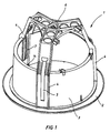
- the basic housing 1 is a recessed ceiling light shown, being pointed out again is that the present invention is not limited to Holder for accessories 24 on recessed ceiling lights is limited.
- the present invention relates rather on the bracket of any shape Accessories on the circumferential edge of a lamp housing.
- Basic housing 1 from a circumferential, radially projecting Ring 2, the one piece with a material approximately vertical, slightly inwardly inclined ring flange 3 is provided.
- struts 4 evenly distributed around the circumference, 4 vertical slots 5 are provided in each strut are, by which spring tabs, not shown reach through.
- spring tabs are used for attachment of the basic housing 1 in a not shown Installation opening.
- Such a spring tab 29 is for example shown in Figure 3, recognizable is that each spring tab 29 with a bent End at assigned locking surfaces 7 on the inside the slots 5 cooperates so as to make a locking Height adjustment of each spring tab 29 in the area of Ensure slot 5.
- the struts 4 converge in the upper part of the basic housing 1 in a plate 6 on which the attachment with a reflector 15 is arranged. Further components are arranged on the basic housing 1 which are not essential for the present invention and are therefore not described in more detail.
- an accessory ring 8 is shown, the essentially from an inner, approximately vertical Ring flange 11, which is horizontal Floor surface 20 with an outer also vertical trained ring flange 10 is connected.
- the two Ring flanges 10,11 form in connection with the Bottom surface 20 a circumferential, approximately U-shaped profiled ring groove 9.
- each snap element 12 carries snap hooks 13, which barbed, resilient heads exhibit.
- the accessory ring 8 For mounting the accessory ring 8 on the basic housing 1 is provided that the accessory ring 8 with its radially outward facing snap hooks 13 in the Inner wall of the basic housing 1 is introduced, the snap hooks 13 rotating all around and radially projecting paragraphs 14 are opposite.
- the snap hooks 13 snap onto these shoulders 14, these shoulders 14 being evenly distributed on the circumference in the area of the struts 4.
- the load is advantageously transmitted via these struts 4 to the fastening elements of the basic housing 1.
- each Holding element essentially from a clamping lever 17th exists, which is rotatably connected to an axis 18 is which axis 18 through an associated hole 19 engages in the bottom surface 20 of the accessory ring 8.
- On the opposite side is the Axis 18, each with a holding arm 21 rotatably connected.
- the clamping lever 17 in the direction of the arrow 23 rotated, then the holding arms 21 pivot about flush below the floor surface 20 and it can now easily an accessory 24 (see Figure 4) be placed on the accessory ring 8.
- the tensioning lever 17 in the direction of the arrow 22 pivot the support arms 21 radially outwards and take their position according to Figure 4. This will the accessory 24 of the evenly on the circumference distributed support arms 21 worn.
- Accessory 24 defines a central recess 26, which is larger than the outer circumference of the outer ring flange 10 of the accessory ring 8.
- the accessory part 24 can have an opening 27, through which light passes, the accessory 24 either colored, translucent or can be partially translucent.
- the reflector 15 follows radially externally facing ring flange 28, the under a circumferential ring flange pointing radially inwards 30 of the accessory ring 8 engages and this can carry or carry.
- the aforementioned snap hooks 13 are arranged.
- the ring flange 10 also serves as Screen.
- the snap connection or snap connection between the accessory ring 8 and the assigned surfaces of the Basic housing 1 can also be designed differently. Instead of using snap hooks in the area of snap elements 12 are arranged, it is possible this snap hook 13 according to Figure 4 without arrangement of Train snap elements.
- connection is made without tools.
- accessories 24 is also Holding arm 21 designed differently.
Landscapes
- Engineering & Computer Science (AREA)
- General Engineering & Computer Science (AREA)
- Fastening Of Light Sources Or Lamp Holders (AREA)
- Non-Portable Lighting Devices Or Systems Thereof (AREA)
- Motorcycle And Bicycle Frame (AREA)
- Securing Globes, Refractors, Reflectors Or The Like (AREA)
Description
Darüber hinaus ist der Anbau von Zubehörteilen jetzt auch ohne Verwendung eines vom Grundgehäuse getrennten Reflektors werkzeuglos möglich.
Die Belastung wird auch hierbei fast vollständig direkt in das Grundgehäuse eingeleitet.
Alle in den Unterlagen - einschließlich der Zusammenfassung - offenbarten Angaben und Merkmale, insbesondere die in den Zeichnungen dargestellte räumliche Ausbildung werden als erfindungswesentlich beansprucht, soweit sie einzeln oder in Kombination gegenüber dem Stand der Technik neu sind.
- Figur 1:
- eine perspektivische Seitenansicht des Grundgehäuses;
- Figur 2:
- eine perspektivische Ansicht des Zubehörrings;
- Figur 3:
- einen Mittenschnitt durch das Grundgehäuse mit eingebautem Reflektor und befestigtem Zubehörring;
- Figur 4:
- eine mögliche Ausführungsform für ein Zubehörteil.
Am Grundgehäuse 1 sind weitere Bauteile angeordnet, die für die vorliegende Erfindung nicht wesentlich sind und daher nicht näher beschrieben werden.
Die Belastung wird vorteilhaft über diese Streben 4 auf die Befestigungselemente des Grundgehäuses 1 übertragen.
- 1
- Grundgehäuse
- 2
- Ring
- 3
- Ringflansch
- 4
- Strebe
- 5
- Schlitz
- 6
- Platte
- 7
- Rastfläche
- 8
- Zubehörring
- 9
- Ringnut
- 10
- Ringflansch (außen)
- 11
- Ringflansch (innen)
- 12
- Schnappelement
- 13
- Schnapphaken
- 14
- Absatz
- 15
- Reflektor
- 16
- Verriegelungsknebel
- 17
- Spannhebel
- 18
- Achse
- 19
- Bohrung
- 20
- Bodenfläche
- 21
- Haltearm
- 22
- Pfeilrichtung
- 23
- Pfeilrichtung
- 24
- Zubehörteil
- 25
- Ringflansch
- 26
- Ausnehmung
- 27
- Öffnung
- 28
- Ringflansch (Reflektor 15)
- 29
- Federlappen
- 30
- Ringflansch (Zubehörring 8)
Claims (7)
- Halterung von Zubehörteilen für Leuchten mit einem Grundgehäuse (1), an dem weitere Anbauteile, insbesondere ein Reflektor (15), befestigt werden können, dadurch gekennzeichnet, daß die Zubehörteile (24) auf einen Zubehörring (8) aufgesetzt werden, daß eine erste lösbare werkzeuglose Verbindung (12,13) zwischen Zubehörring (8) und Grundgehäuse (1) vorgesehen ist, wobei der Zubehörring (8) direkt an dem Grundgehäuse (1) befestigt wird, und daß eine weitere lösbare werkzeuglose Verbindung (17,18,21) zwischen den Zubehörteilen (24) und dem Zubehörring (8) vorgesehen ist.
- Halterung nach Anspruch 1, dadurch gekennzeichnet, daß die Verbindung zwischen dem Zubehörring (8) und dem Grundgehäuse (1) über eine Schnapp- oder eine Rastverbindung erfolgt.
- Halterung nach einem der Ansprüche 1 oder 2, dadurch gekennzeichnet, daß die Verbindung zwischen dem Zubehörring (8) und dem Grundgehäuse (1) direkt am Ringflansch (3) des Grundgehäuses (1) angebracht ist.
- Halterung nach einem der Ansprüche 1 - 3, dadurch gekennzeichnet, daß der Zubehörring (8) mit schwenkbaren Halteelementen versehen ist.
- Halterung nach Anspruch 4, dadurch gekennzeichnet, daß die Arretierung der Halteelemente in verschiedenen Stellungen vorgesehen ist.
- Halterung nach einem der Ansprüche 1 - 5, dadurch gekennzeichnet, daß ein Reflektor (15) vorgesehen ist, der mit einem Ringflansch (28) den Verbindungsbereich zwischen dem Grundgehäuse (1) und dem Zubehörring (8) überdeckt.
- Halterung nach Anspruch 6, dadurch gekennzeichnet, daß die Verbindung zwischen Reflektor (15) und Grundgehäuse (1) lösbar und wiederverschließbar ausgebildet ist.
Applications Claiming Priority (2)
| Application Number | Priority Date | Filing Date | Title |
|---|---|---|---|
| DE4344431A DE4344431A1 (de) | 1993-12-24 | 1993-12-24 | Halterung von Zubehörteilen für Leuchten |
| DE4344431 | 1993-12-24 |
Publications (2)
| Publication Number | Publication Date |
|---|---|
| EP0660033A1 EP0660033A1 (de) | 1995-06-28 |
| EP0660033B1 true EP0660033B1 (de) | 1998-05-20 |
Family
ID=6506182
Family Applications (1)
| Application Number | Title | Priority Date | Filing Date |
|---|---|---|---|
| EP94117971A Expired - Lifetime EP0660033B1 (de) | 1993-12-24 | 1994-11-15 | Halterung von Zubehörteilen für Leuchten |
Country Status (3)
| Country | Link |
|---|---|
| EP (1) | EP0660033B1 (de) |
| AT (1) | ATE166444T1 (de) |
| DE (2) | DE4344431A1 (de) |
Families Citing this family (4)
| Publication number | Priority date | Publication date | Assignee | Title |
|---|---|---|---|---|
| DE10013087A1 (de) | 2000-03-17 | 2001-09-20 | Zumtobel Staff Gmbh & Co Kg | Einbauleuchte mit einem Haltering für Zusatzbauteile |
| DE20004985U1 (de) | 2000-03-17 | 2001-07-26 | Zumtobel Staff GmbH & Co. KG, 32657 Lemgo | Leuchte, insbesondere Einbauleuchte |
| DE202008004448U1 (de) * | 2008-04-01 | 2009-08-13 | Zumtobel Lighting Gmbh & Co. Kg | Strahlerleuchte |
| US20180172260A1 (en) * | 2016-12-20 | 2018-06-21 | GE Lighting Solutions, LLC | Luminaire housing assembly |
Family Cites Families (9)
| Publication number | Priority date | Publication date | Assignee | Title |
|---|---|---|---|---|
| AT338378B (de) * | 1976-03-19 | 1977-08-25 | Licentia Gmbh | Drehriegelverschluss fur leuchtengehause |
| FR2595133B1 (fr) * | 1986-03-03 | 1988-05-27 | Soudures Applic Electr | Module encastrable renfermant un equipement, notamment d'eclairage |
| IT213179Z2 (it) * | 1987-12-23 | 1989-11-09 | Reggiani Illuminazione | Dispositivo di illiminazione con anello per il bloccaggio della parabola tramite molla. |
| DE9017403U1 (de) * | 1990-12-22 | 1991-04-04 | Großkinsky, Wilfried, 5000 Köln | Leuchte, insbesondere Decken- oder Wandleuchte |
| FI86766C (fi) * | 1991-04-09 | 1993-04-27 | Idman Oy | Anordning vid en belysningsapparat |
| DE9112496U1 (de) * | 1991-10-08 | 1991-12-05 | Pöllet, Wilfried, 8501 Schwanstetten | Strahler |
| FR2683616B1 (fr) * | 1991-11-08 | 1997-09-05 | Sedap Atelier | Appareil d'eclairage encastrable, partie decorative associee et insert pour une telle partie decorative. |
| DE9306300U1 (de) * | 1993-04-20 | 1993-06-17 | Norka Norddeutsche Kunststoff- und Elektro-Gesellschaft Stäcker & Co. mbH, 2000 Hamburg | Deckeneinbaustrahler |
| DE9317087U1 (de) * | 1993-11-09 | 1994-01-20 | eurolicht GmbH, 53773 Hennef | Einbauleuchte |
-
1993
- 1993-12-24 DE DE4344431A patent/DE4344431A1/de not_active Withdrawn
-
1994
- 1994-11-15 AT AT94117971T patent/ATE166444T1/de not_active IP Right Cessation
- 1994-11-15 DE DE59406021T patent/DE59406021D1/de not_active Expired - Fee Related
- 1994-11-15 EP EP94117971A patent/EP0660033B1/de not_active Expired - Lifetime
Also Published As
| Publication number | Publication date |
|---|---|
| EP0660033A1 (de) | 1995-06-28 |
| ATE166444T1 (de) | 1998-06-15 |
| DE4344431A1 (de) | 1995-06-29 |
| DE59406021D1 (de) | 1998-06-25 |
Similar Documents
| Publication | Publication Date | Title |
|---|---|---|
| DE3880470T2 (de) | Armatur fuer treibhausbeleuchtung. | |
| EP2093478A1 (de) | Einbauleuchte | |
| DE20002168U1 (de) | Leuchtenanordnung | |
| DE2943544C2 (de) | Befestigung einer lichtdurchlässigen Scheibe | |
| EP0660036B1 (de) | Fassungsträger für eine Deckeneinbauleuchte | |
| DE102011083993A1 (de) | Lichtband | |
| EP0660033A1 (de) | Halterung von Zubehörteilen für Leuchten | |
| EP2404105B1 (de) | Montagevorrichtung für deckeneinbauleuchte | |
| DE19954735B4 (de) | Leuchte für den Einbau in eine Öffnung in einer Einbaufläche | |
| DE9320823U1 (de) | Schnellverschluß für Leuchteneinsätze | |
| DE3014241A1 (de) | Vorrichtung zum verbinden von leuchten zu lichtbaendern bzw. lichtbandfiguren | |
| DE102008017462B3 (de) | Langgestreckte Hängeleuchte | |
| DE20004985U1 (de) | Leuchte, insbesondere Einbauleuchte | |
| DE69716020T2 (de) | Leuchte, insbesondere Sicherheits- Beleuchtungsblock | |
| DE202008008123U1 (de) | Leuchte | |
| DE19949907A1 (de) | Heckleuchte für ein Fahrzeug | |
| DE922424C (de) | Decken- und Wandleuchte | |
| DE20103348U1 (de) | Dekorationsgegenstand | |
| DE20119134U1 (de) | Deckeneinbauleuchte | |
| DE10248705A1 (de) | Adapter zur Befestigung von Leuchtenbauteilen | |
| DE202018102957U1 (de) | Scharnier für eine Toilettensitzgarnitur | |
| DE29710612U1 (de) | Vorsatz mit Haltekrallen für Einbau-Leuchten | |
| DE9217869U1 (de) | Leuchte mit Abdeckung | |
| DE29810886U1 (de) | Anordnung bestehend aus zumindest zwei miteinander verbundenen ringförmigen Körpern sowie Leuchte mit einer solchen Anordnung | |
| DE202005019709U1 (de) | Laterne, insbesondere Grablaterne |
Legal Events
| Date | Code | Title | Description |
|---|---|---|---|
| PUAI | Public reference made under article 153(3) epc to a published international application that has entered the european phase |
Free format text: ORIGINAL CODE: 0009012 |
|
| AK | Designated contracting states |
Kind code of ref document: A1 Designated state(s): AT BE CH DE FR GB IT LI NL SE |
|
| 17P | Request for examination filed |
Effective date: 19951014 |
|
| 17Q | First examination report despatched |
Effective date: 19970207 |
|
| GRAG | Despatch of communication of intention to grant |
Free format text: ORIGINAL CODE: EPIDOS AGRA |
|
| GRAG | Despatch of communication of intention to grant |
Free format text: ORIGINAL CODE: EPIDOS AGRA |
|
| GRAH | Despatch of communication of intention to grant a patent |
Free format text: ORIGINAL CODE: EPIDOS IGRA |
|
| GRAH | Despatch of communication of intention to grant a patent |
Free format text: ORIGINAL CODE: EPIDOS IGRA |
|
| GRAA | (expected) grant |
Free format text: ORIGINAL CODE: 0009210 |
|
| AK | Designated contracting states |
Kind code of ref document: B1 Designated state(s): AT BE CH DE FR GB IT LI NL SE |
|
| REF | Corresponds to: |
Ref document number: 166444 Country of ref document: AT Date of ref document: 19980615 Kind code of ref document: T |
|
| REG | Reference to a national code |
Ref country code: CH Ref legal event code: EP |
|
| REF | Corresponds to: |
Ref document number: 59406021 Country of ref document: DE Date of ref document: 19980625 |
|
| ITF | It: translation for a ep patent filed | ||
| REG | Reference to a national code |
Ref country code: CH Ref legal event code: NV Representative=s name: LUCHS & PARTNER PATENTANWAELTE |
|
| GBT | Gb: translation of ep patent filed (gb section 77(6)(a)/1977) |
Effective date: 19980820 |
|
| ET | Fr: translation filed | ||
| PLBE | No opposition filed within time limit |
Free format text: ORIGINAL CODE: 0009261 |
|
| STAA | Information on the status of an ep patent application or granted ep patent |
Free format text: STATUS: NO OPPOSITION FILED WITHIN TIME LIMIT |
|
| 26N | No opposition filed | ||
| REG | Reference to a national code |
Ref country code: GB Ref legal event code: IF02 |
|
| PGFP | Annual fee paid to national office [announced via postgrant information from national office to epo] |
Ref country code: GB Payment date: 20020926 Year of fee payment: 9 |
|
| PGFP | Annual fee paid to national office [announced via postgrant information from national office to epo] |
Ref country code: SE Payment date: 20021119 Year of fee payment: 9 |
|
| PGFP | Annual fee paid to national office [announced via postgrant information from national office to epo] |
Ref country code: FR Payment date: 20021125 Year of fee payment: 9 |
|
| PGFP | Annual fee paid to national office [announced via postgrant information from national office to epo] |
Ref country code: BE Payment date: 20021129 Year of fee payment: 9 |
|
| PGFP | Annual fee paid to national office [announced via postgrant information from national office to epo] |
Ref country code: NL Payment date: 20021130 Year of fee payment: 9 |
|
| PG25 | Lapsed in a contracting state [announced via postgrant information from national office to epo] |
Ref country code: GB Free format text: LAPSE BECAUSE OF NON-PAYMENT OF DUE FEES Effective date: 20031115 |
|
| PG25 | Lapsed in a contracting state [announced via postgrant information from national office to epo] |
Ref country code: SE Free format text: LAPSE BECAUSE OF NON-PAYMENT OF DUE FEES Effective date: 20031116 |
|
| PG25 | Lapsed in a contracting state [announced via postgrant information from national office to epo] |
Ref country code: BE Free format text: LAPSE BECAUSE OF NON-PAYMENT OF DUE FEES Effective date: 20031130 |
|
| BERE | Be: lapsed |
Owner name: *ZUMTOBEL LICHT G.M.B.H. Effective date: 20031130 |
|
| PG25 | Lapsed in a contracting state [announced via postgrant information from national office to epo] |
Ref country code: NL Free format text: LAPSE BECAUSE OF NON-PAYMENT OF DUE FEES Effective date: 20040601 |
|
| EUG | Se: european patent has lapsed | ||
| GBPC | Gb: european patent ceased through non-payment of renewal fee |
Effective date: 20031115 |
|
| PG25 | Lapsed in a contracting state [announced via postgrant information from national office to epo] |
Ref country code: FR Free format text: LAPSE BECAUSE OF NON-PAYMENT OF DUE FEES Effective date: 20040730 |
|
| NLV4 | Nl: lapsed or anulled due to non-payment of the annual fee |
Effective date: 20040601 |
|
| REG | Reference to a national code |
Ref country code: FR Ref legal event code: ST |
|
| PG25 | Lapsed in a contracting state [announced via postgrant information from national office to epo] |
Ref country code: IT Free format text: LAPSE BECAUSE OF NON-PAYMENT OF DUE FEES;WARNING: LAPSES OF ITALIAN PATENTS WITH EFFECTIVE DATE BEFORE 2007 MAY HAVE OCCURRED AT ANY TIME BEFORE 2007. THE CORRECT EFFECTIVE DATE MAY BE DIFFERENT FROM THE ONE RECORDED. Effective date: 20051115 |
|
| PGFP | Annual fee paid to national office [announced via postgrant information from national office to epo] |
Ref country code: DE Payment date: 20051122 Year of fee payment: 12 |
|
| PGFP | Annual fee paid to national office [announced via postgrant information from national office to epo] |
Ref country code: AT Payment date: 20051130 Year of fee payment: 12 |
|
| PGFP | Annual fee paid to national office [announced via postgrant information from national office to epo] |
Ref country code: CH Payment date: 20060222 Year of fee payment: 12 |
|
| PG25 | Lapsed in a contracting state [announced via postgrant information from national office to epo] |
Ref country code: AT Free format text: LAPSE BECAUSE OF NON-PAYMENT OF DUE FEES Effective date: 20061115 |
|
| PG25 | Lapsed in a contracting state [announced via postgrant information from national office to epo] |
Ref country code: LI Free format text: LAPSE BECAUSE OF NON-PAYMENT OF DUE FEES Effective date: 20061130 Ref country code: CH Free format text: LAPSE BECAUSE OF NON-PAYMENT OF DUE FEES Effective date: 20061130 |
|
| PG25 | Lapsed in a contracting state [announced via postgrant information from national office to epo] |
Ref country code: DE Free format text: LAPSE BECAUSE OF NON-PAYMENT OF DUE FEES Effective date: 20070601 |
|
| REG | Reference to a national code |
Ref country code: CH Ref legal event code: PL |