EP0655740B1 - Verwaltungsverfahren für ein aufzeichnungsmedium - Google Patents
Verwaltungsverfahren für ein aufzeichnungsmedium Download PDFInfo
- Publication number
- EP0655740B1 EP0655740B1 EP94917813A EP94917813A EP0655740B1 EP 0655740 B1 EP0655740 B1 EP 0655740B1 EP 94917813 A EP94917813 A EP 94917813A EP 94917813 A EP94917813 A EP 94917813A EP 0655740 B1 EP0655740 B1 EP 0655740B1
- Authority
- EP
- European Patent Office
- Prior art keywords
- data
- recording
- recording medium
- recorded
- area
- Prior art date
- Legal status (The legal status is an assumption and is not a legal conclusion. Google has not performed a legal analysis and makes no representation as to the accuracy of the status listed.)
- Expired - Lifetime
Links
Images


Classifications
-
- G—PHYSICS
- G11—INFORMATION STORAGE
- G11B—INFORMATION STORAGE BASED ON RELATIVE MOVEMENT BETWEEN RECORD CARRIER AND TRANSDUCER
- G11B20/00—Signal processing not specific to the method of recording or reproducing; Circuits therefor
- G11B20/10—Digital recording or reproducing
- G11B20/12—Formatting, e.g. arrangement of data block or words on the record carriers
- G11B20/1217—Formatting, e.g. arrangement of data block or words on the record carriers on discs
- G11B20/1251—Formatting, e.g. arrangement of data block or words on the record carriers on discs for continuous data, e.g. digitised analog information signals, pulse code modulated [PCM] data
-
- G—PHYSICS
- G11—INFORMATION STORAGE
- G11B—INFORMATION STORAGE BASED ON RELATIVE MOVEMENT BETWEEN RECORD CARRIER AND TRANSDUCER
- G11B27/00—Editing; Indexing; Addressing; Timing or synchronising; Monitoring; Measuring tape travel
-
- G—PHYSICS
- G06—COMPUTING OR CALCULATING; COUNTING
- G06F—ELECTRIC DIGITAL DATA PROCESSING
- G06F16/00—Information retrieval; Database structures therefor; File system structures therefor
- G06F16/90—Details of database functions independent of the retrieved data types
- G06F16/901—Indexing; Data structures therefor; Storage structures
- G06F16/9017—Indexing; Data structures therefor; Storage structures using directory or table look-up
- G06F16/902—Indexing; Data structures therefor; Storage structures using directory or table look-up using more than one table in sequence, i.e. systems with three or more layers
-
- G—PHYSICS
- G11—INFORMATION STORAGE
- G11B—INFORMATION STORAGE BASED ON RELATIVE MOVEMENT BETWEEN RECORD CARRIER AND TRANSDUCER
- G11B20/00—Signal processing not specific to the method of recording or reproducing; Circuits therefor
- G11B20/10—Digital recording or reproducing
- G11B20/12—Formatting, e.g. arrangement of data block or words on the record carriers
- G11B20/1217—Formatting, e.g. arrangement of data block or words on the record carriers on discs
- G11B20/1252—Formatting, e.g. arrangement of data block or words on the record carriers on discs for discontinuous data, e.g. digital information signals or computer program data
-
- G—PHYSICS
- G11—INFORMATION STORAGE
- G11B—INFORMATION STORAGE BASED ON RELATIVE MOVEMENT BETWEEN RECORD CARRIER AND TRANSDUCER
- G11B27/00—Editing; Indexing; Addressing; Timing or synchronising; Monitoring; Measuring tape travel
- G11B27/02—Editing, e.g. varying the order of information signals recorded on, or reproduced from, record carriers
- G11B27/031—Electronic editing of digitised analogue information signals, e.g. audio or video signals
- G11B27/034—Electronic editing of digitised analogue information signals, e.g. audio or video signals on discs
-
- G—PHYSICS
- G11—INFORMATION STORAGE
- G11B—INFORMATION STORAGE BASED ON RELATIVE MOVEMENT BETWEEN RECORD CARRIER AND TRANSDUCER
- G11B27/00—Editing; Indexing; Addressing; Timing or synchronising; Monitoring; Measuring tape travel
- G11B27/10—Indexing; Addressing; Timing or synchronising; Measuring tape travel
- G11B27/11—Indexing; Addressing; Timing or synchronising; Measuring tape travel by using information not detectable on the record carrier
-
- G—PHYSICS
- G11—INFORMATION STORAGE
- G11B—INFORMATION STORAGE BASED ON RELATIVE MOVEMENT BETWEEN RECORD CARRIER AND TRANSDUCER
- G11B27/00—Editing; Indexing; Addressing; Timing or synchronising; Monitoring; Measuring tape travel
- G11B27/10—Indexing; Addressing; Timing or synchronising; Measuring tape travel
- G11B27/19—Indexing; Addressing; Timing or synchronising; Measuring tape travel by using information detectable on the record carrier
- G11B27/28—Indexing; Addressing; Timing or synchronising; Measuring tape travel by using information detectable on the record carrier by using information signals recorded by the same method as the main recording
- G11B27/32—Indexing; Addressing; Timing or synchronising; Measuring tape travel by using information detectable on the record carrier by using information signals recorded by the same method as the main recording on separate auxiliary tracks of the same or an auxiliary record carrier
- G11B27/327—Table of contents
- G11B27/329—Table of contents on a disc [VTOC]
-
- G—PHYSICS
- G11—INFORMATION STORAGE
- G11B—INFORMATION STORAGE BASED ON RELATIVE MOVEMENT BETWEEN RECORD CARRIER AND TRANSDUCER
- G11B11/00—Recording on or reproducing from the same record carrier wherein for these two operations the methods are covered by different main groups of groups G11B3/00 - G11B7/00 or by different subgroups of group G11B9/00; Record carriers therefor
- G11B11/10—Recording on or reproducing from the same record carrier wherein for these two operations the methods are covered by different main groups of groups G11B3/00 - G11B7/00 or by different subgroups of group G11B9/00; Record carriers therefor using recording by magnetic means or other means for magnetisation or demagnetisation of a record carrier, e.g. light induced spin magnetisation; Demagnetisation by thermal or stress means in the presence or not of an orienting magnetic field
- G11B11/105—Recording on or reproducing from the same record carrier wherein for these two operations the methods are covered by different main groups of groups G11B3/00 - G11B7/00 or by different subgroups of group G11B9/00; Record carriers therefor using recording by magnetic means or other means for magnetisation or demagnetisation of a record carrier, e.g. light induced spin magnetisation; Demagnetisation by thermal or stress means in the presence or not of an orienting magnetic field using a beam of light or a magnetic field for recording by change of magnetisation and a beam of light for reproducing, i.e. magneto-optical, e.g. light-induced thermomagnetic recording, spin magnetisation recording, Kerr or Faraday effect reproducing
- G11B11/10582—Record carriers characterised by the selection of the material or by the structure or form
- G11B11/10584—Record carriers characterised by the selection of the material or by the structure or form characterised by the form, e.g. comprising mechanical protection elements
-
- G—PHYSICS
- G11—INFORMATION STORAGE
- G11B—INFORMATION STORAGE BASED ON RELATIVE MOVEMENT BETWEEN RECORD CARRIER AND TRANSDUCER
- G11B11/00—Recording on or reproducing from the same record carrier wherein for these two operations the methods are covered by different main groups of groups G11B3/00 - G11B7/00 or by different subgroups of group G11B9/00; Record carriers therefor
- G11B11/10—Recording on or reproducing from the same record carrier wherein for these two operations the methods are covered by different main groups of groups G11B3/00 - G11B7/00 or by different subgroups of group G11B9/00; Record carriers therefor using recording by magnetic means or other means for magnetisation or demagnetisation of a record carrier, e.g. light induced spin magnetisation; Demagnetisation by thermal or stress means in the presence or not of an orienting magnetic field
- G11B11/105—Recording on or reproducing from the same record carrier wherein for these two operations the methods are covered by different main groups of groups G11B3/00 - G11B7/00 or by different subgroups of group G11B9/00; Record carriers therefor using recording by magnetic means or other means for magnetisation or demagnetisation of a record carrier, e.g. light induced spin magnetisation; Demagnetisation by thermal or stress means in the presence or not of an orienting magnetic field using a beam of light or a magnetic field for recording by change of magnetisation and a beam of light for reproducing, i.e. magneto-optical, e.g. light-induced thermomagnetic recording, spin magnetisation recording, Kerr or Faraday effect reproducing
- G11B11/10595—Control of operating function
-
- G—PHYSICS
- G11—INFORMATION STORAGE
- G11B—INFORMATION STORAGE BASED ON RELATIVE MOVEMENT BETWEEN RECORD CARRIER AND TRANSDUCER
- G11B20/00—Signal processing not specific to the method of recording or reproducing; Circuits therefor
- G11B20/10—Digital recording or reproducing
- G11B20/10527—Audio or video recording; Data buffering arrangements
- G11B2020/10537—Audio or video recording
- G11B2020/10592—Audio or video recording specifically adapted for recording or reproducing multichannel signals
-
- G—PHYSICS
- G11—INFORMATION STORAGE
- G11B—INFORMATION STORAGE BASED ON RELATIVE MOVEMENT BETWEEN RECORD CARRIER AND TRANSDUCER
- G11B2220/00—Record carriers by type
- G11B2220/20—Disc-shaped record carriers
- G11B2220/25—Disc-shaped record carriers characterised in that the disc is based on a specific recording technology
- G11B2220/2525—Magneto-optical [MO] discs
- G11B2220/2529—Mini-discs
-
- G—PHYSICS
- G11—INFORMATION STORAGE
- G11B—INFORMATION STORAGE BASED ON RELATIVE MOVEMENT BETWEEN RECORD CARRIER AND TRANSDUCER
- G11B2220/00—Record carriers by type
- G11B2220/60—Solid state media
- G11B2220/65—Solid state media wherein solid state memory is used for storing indexing information or metadata
Definitions
- This invention relates to a recording medium management method suitable when used in the case of recording digital data to be processed by computer onto a magneto-optical disc on which digital audio data is primarily recorded in compressed manner, or reproducing it from such a magneto-optical disc, and to a system and to a recording medium using said method.
- mini-discs (MD) (Tradename) using magneto-optical disc as recording medium, and adapted for compressing digital audio data to record compressed data thereonto and expanding such compressed data to reproduce therefrom data corresponding to original data
- Fig. 29 shows a recording format in this mini-disc. As shown in this figure, one circumference of the mini-disc is divided into a plurality of sectors. One cluster is constituted by 36 sectors, and compressed digital audio data is recorded with this cluster being as unit.
- sub data sector sub data except for audio data is allocated.
- the link sector is caused to serve as an area for connecting clusters before and after, and audio data is recorded only in 32 sectors except for the link sector and the sub data sector.
- One sector consists of 2352 bytes (2332 bytes for data), and 11 sound groups are allocated to two successive sectors.
- One sound group consists of 424 bytes, and audio data of the left channel and the right channel are allocated thereto by 512 samples (11.61 ms) in total. Recording of digital audio data is carried out with the sound group being as unit.
- mini-disc as, e.g., storage unit of computer.
- cluster 36 sectors
- a unit e.g., sector unit
- mini-disc since it is prescribed by the standardization requirements that mini-disc must record data thereonto with one cluster being as unit, there is the problem that it is unable to record data in a unit smaller than one cluster (e.g., sector unit).
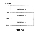
- the recording area is partitioned into area (A) from cluster 0 up to cluster 650, area (B) from cluster 651 up to cluster 1100, and area (C) from cluster 1101 up to cluster 2199, thus making it possible to record audio data into, e.g., partitions A and C of respective areas (partitions), and to record data of computer into partition B thereof.
- management method of dividing the recording area into partitions in this way is management method basically different from the management method having cluster as unit.
- a mini-disc having a recording area divided into a plurality of partitions in which data of computer is recorded in a predetermined partition and audio data is recorded in any other partition is reproduced by an apparatus dedicated for reproducing audio data, there is the possibility that the audio data may not be reproduced. Namely, it becomes difficult to guarantee compatibility.
- it is an object of the present invention to broaden the usability of such recording media i.e. to make it possible to record data in a data recording unit which may be smaller than a standarized one for recording data. This object is solved according to the method of claim 1. Further advantageous features are set forth in the dependent claims.
- the invention provides for a system and recording medium using the recording medium management method of this invention. Further, in accordance with this invention, in the case where an empty area exists, it is possible to record both computer data and audio data at all times as occasion demands. In addition, this invention makes it possible to ensure compatibility with ordinary mini-disc.
- a predetermined range or area is designated from the area caused to undergo management by the first or management table of U-TOC, and the designated area is caused to undergo management by the second table or FAT or bitmap. Accordingly, it is possible to record computer data in the designated area with a second data recording unit or sector smaller than a first data recording unit or cluster. Further, such designation is supplemented as occasion demands, thereby making it possible to supplementarily record not only digital audio data but also computer data as long as any empty area exists. In addition, compatibility with mini-discs on which only ordinary data are recorded is ensured.
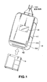
- FIG. 1 shows the configuration of appearance of an embodiment of a mini-disc device to which a recording medium management method of this invention is applied.
- a mini-disc 1 (FIG. 2) is accommodated.
- This cartridge 1a is adapted so that it can be loaded into body 41 from opening for insertion designated at 42.
- an operation input section 19 including power switch 19 in the form of push-button and eject push-button 19b, etc. is provided at the bottom portion on the right side of body 41.
- the power switch 19a is operated when the power supply is turned ON or OFF, and the eject push-button 19b is operated when cartridge 1a is ejected.
- display section 18 is disposed at the central portion on the upper surface of body 41.
- the body 41 is connected to host CPU 31 (FIG. 2) through SCSI bus 30.
- FIG. 2 shows the internal configuration of body 41.
- mini-disc (magneto-optical disc) 1 on which, e.g., both a plurality of musical pieces (audio data) and computer data, or only computer data are or is recorded is rotationally driven by spindle motor 2.
- Optical head 3 irradiates laser beams to mini-disc 1 at the time of recording/reproduction. Namely, at the time of recording, laser beams of high level for heating recording tracks to Curie temperature are outputted. On the other hand, at the time of reproduction, laser beams of a relatively lower level for detecting data from a reflected light by the magnetic kerr effect are outputted.
- optical head 3 includes a laser diode for outputting laser beams, an optical system composed of a polarizing beam splitter, object lens (objective) and the like, and a detector for detecting a reflected light.
- object lens 3a is held so that it can undergo displacement in a disc radial direction (tracking direction) and a direction in which it is in contact with the disc or is away therefrom (focus direction) by biaxial mechanism 4, and the entirety of optical head 3 can be moved in a disc radial direction by sled mechanism 5.
- magnetic head 6 is disposed at the position opposite to optical head 3 with mini-disc 1 being put between magnetic head 6 and optical head 3 so as to apply, to mini-disc 1, magnetic field modulated by data delivered to the magnetic head 6.
- the RF amplifier 7 extracts, by operation processing of information delivered thereto, reproduction RF signal, tracking error signal, focus error signal, ATIP information (absolute time information recorded as pregroove (wobbling groove) on mini-disc 1), address information, sub code information, and focus monitor signal, etc.
- the extracted reproduction RF signal is delivered to encoder/decoder section 8. Moreover, tracking error signal and focus error signal are delivered to servo circuit 9, and address information is delivered to address decoder 10. Further, ATIP information and focus monitor signal are delivered to system controller 11 comprised of, e.g., microcomputer (CPU).
- system controller 11 comprised of, e.g., microcomputer (CPU).
- the servo circuit 9 generates various servo drive signals by tracking error signal and focus error signal delivered from RF amplifier 7, and track jump command, seek command and rotational speed detection information, etc. from system controller 11 to control biaxial mechanism 4 and sled mechanism 5 to allow them to carry out focus and tracking controls, and to control spindle motor 2 so that it is driven at a constant angular velocity (CAV) or at a constant linear velocity (CLV).
- CAV constant angular velocity
- CLV constant linear velocity
- Reproduction RF signal is EFM-demodulated at encoder/decoder section 8.
- the signal thus modulated is caused to undergo decode processing such as CIRC, etc., and is then once written into buffer RAM 13 by memory controller 12.
- decode processing such as CIRC, etc.
- reading of data from mini-disc 1 by optical head 3 and transfer of reproduction data from optical head 3 up to buffer RAM 13 are carried out at a transfer rate of 1.41 M bits/sec.
- Address information outputted from address decoder 10 is delivered to system controller 11 through encoder/decoder section 8, at which it is used for various control operations.
- lock detection signal of PLL circuit for generating bit clock of recording/reproducing operation and signal for monitoring missing state of frame synchronizing signal of reproduction data are also delivered to system controller 11.
- recording data is delivered to memory controller 12 through SCSI interface 14 by host CPU 31.
- This recording data is once written into buffer RAM 13 by memory controller 12, and is read out therefrom at a predetermined timing.
- the signal thus read out is sent to encoder/decoder section 8.
- predetermined processing such as CIRC encode, EFM modulation, etc. are implemented thereto.
- the signal thus processed is delivered to magnetic head drive circuit 15.
- the magnetic head drive circuit 15 delivers magnetic head drive signal to magnetic head 6 in dependency upon the recording data which has undergone encode and modulation processing, etc. Namely, mini-disc 1 is caused to execute application of magnetic field of N or S by magnetic head 6 with respect to mini-disc 1.
- system controller 11 delivers, to optical head 3, a control signal so as to output laser beams of recording level.
- a predetermined character, etc. is displayed in correspondence with command from system controller 11.
- the operation input section 19 includes reproduction key, stop key, AMS key and search key, etc. in addition to the above-described power switch 19a, eject push-button 19b, and inputs a signal corresponding to that operation to system controller 11.
- TOC memory 16 holds TOC information in mini-disc 1.
- system controller 11 drives spindle motor 2 and optical head 3 to extract data in TOC area set, e.g., on the innermost circumferential side of mini-disc 1.
- TOC information delivered to system controller 11 through RF amplifier 7 and encoder/decoder section 8 is stored into TOC memory 16. After that, such information is used for control of recording/reproducing operation with respect to that mini-disc 1.
- Memory 17 stores FAT (File Allocation Table) information or bitmap which will be described later.
- Host CPU 31 not only carries out control of transmission/reception of computer data, but also control transmission/reception of FAT information or bitmap, or updating of FAT information or bitmap. It is to be noted that memory 17 may be provided on the body 41 side.
- segment management data for permitting a series of musical pieces to be discretely (or continuously) recorded/reproduced as one segment (parts) or plural divided segments (parts) is further recorded.
- U-TOC recording data area user TOC
- U-TOC such that the content is rewritten in accordance with recording or erasing of data is recorded in the form of data structure as shown in FIG. 3, for example.
- This U-TOC is recorded in the area of, e.g., 4 bytes x 587 within data area.
- header having synchronization patterns each comprised of 1 byte data of which respective bits are all 0 or all 1 are provided at the leading position in order that this area indicates U-TOC area.
- each parts table there can be recorded start address serving as starting point with respect to a certain segment, end address serving as terminating point thereof, mode information of that segment (track), and link information in which when that segment is continuously connected to any other segment, it indicates parts table where start address and end address of the segment to be connected are recorded.
- mode information of track is information indicating whether or not that track is set to, e.g., overwrite protection or data copy protection, information indicating kind of audio information or computer information, etc., information indicating kind of monaural/stereo, and the like.
- Link information designates a parts table to be connected by, e.g., numbers (01h) ⁇ (FFh) given to respective parts tables.
- one parts table represents one segment.
- management of that segment position is carried out by three parts tables connected by link information.
- numbers (01h) ⁇ (FFh) of parts tables can be segment (parts) numbers as they are.
- any defective segment exists, any one of (01h) ⁇ (FFh) is recorded into the area of correspondence table indication data P-DFA, and defective segment is indicated by start and end addresses in parts table corresponding thereto.
- corresponding other parts table is designated as link information in that parts table, and defective segment is indicated also in that parts table.
- link information is caused to be, e.g., (00h), and it is indicated that no segment is linked in areas succeeding thereto.
- P-EMPTY indicates one unused parts table or the leading parts table of plural parts tables in the management table.
- any one of (01h) ⁇ (FFh) is recorded as correspondence table indication data P-EMPTY.
- parts tables are sequentially designated by link information from part table designated by correspondence table indication data P-EMPTY.
- all unused parts table are connected (linked) on the management table. For example, in the case of the magneto-optical disc on which no data is recorded and there is no defective, all parts tables are not used.
- connection to parts table (FFh) is carried out such that, e.g., parts table (01h) is designated by correspondence table indication data P-EMPTY, parts table (02h) is designated as link information of parts table (01h), and parts table (03h) is designated as link information of parts table (02h).
- link information of parts table (FFh) is caused to be (00h) indicating that there is no connection at areas succeeding thereto.
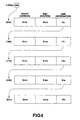
- P-FRA indicates a unrecorded area (including erase area) of data on mini-disc 1, and designates one parts table or the leading parts table within plural parts tables where track portion (segment) serving as unrecorded area is indicated. Namely, in the case where any unrecorded area exists, any one of (01h) ⁇ (FFh) is recorded in the area of correspondence table indication data P-FRA. In a parts table corresponding thereto, segment serving as a unrecorded area is indicated by start address and end address. In addition, in the case where there are a plurality of segments described above, i.e., there are a plurality of parts tables, designation up to the parts table where link information is caused to be (00h) by is sequentially carried out link information.
- FIG. 4 shows the state where when segments where start addresses and end addresses are respectively indicated by (S 03h , E 03h ), (S 18h , E 18h ), (S 1Fh , E 1Fh ), (S 2Bh , E 2Bh ), (S E3h , E E3h ) are caused to be unrecorded area, such segment unrecorded area arrangement state is represented, subsequently to correspondence table indication data P-FRA, by link of parts tables (03h), (18h), (1Fh), (2Bh), (E3h). It is to be noted that management mode of defective area and/or unused parts table described above are the same as the state shown in FIG. 4.
- P-TN01 ⁇ P-TN0255 indicate areas with respect to respective musical pieces (tracks) recorded on mini-disc 1.
- correspondence table indication data P-TN01 designates parts table in which one segment or the leading segment in point of time of plural segments where data of the first musical piece is recorded.
- recording area of the first musical piece is recorded as start and end addresses in the parts table indicated by correspondence table indication data P-TN01.
- respective segments are designated (linked) in accordance with order in point of time for the purpose of indicating the position of that musical piece.
- other parts tables are further sequentially designated in accordance with order in point of time by link information from parts table designated by correspondence table indication data P-TN02, and connection up to parts table where link information is caused to be (00h) is carried out (the same mode as that of FIG. 4).
- U-TOC data recorded on mini-disc 1 is read out and is stored into TOC memory 16.
- U-TOC data which has been read into TOC memory 16 is used to carry out management of the recording area on disc, thus making it possible to control the recording/reproducing operation.
- U-TOC data is also recorded similarly as in the case of mini-disc. on which ordinary musical pieces are recorded.
- mini-disc of this embodiment in order to have ability of recording, e.g., computer data except for audio data (musical piece), LOFAT (Location of FAT) is recorded as data of 16 bits. This LOFAT will be described later.
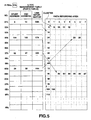
- FIG. 5 shows, in a model form, the relationship between management table (parts table) of U-TOC and cluster of data recording area of mini-disc 1.
- This example indicates unrecorded area of data on mini-disc 1.
- Parts table No. indicating the leading cluster of the unrecorded area is prescribed as (01h) in correspondence table indication data P-FRA. Namely, position of the leading segment as unrecorded area of data is described in parts table (01h).
- (04h) is described as link information of this number (0Ah).
- its start address is caused to be cluster 104 and its end address is caused to be cluster 105. Namely, it is seen that unrecorded area consisting of clusters 104 and 105 exists as the third segment subsequent to cluster 29 and cluster 30.
- link information of (07h) is described in the parts table of (04h).
- parts table of (07h) When attention is drawn to parts table of (07h), its start address is caused to be cluster 82 and its end address is caused to be cluster 87. Namely, the forth segment from cluster 82 to cluster 87 is caused to be unrecorded area. Since (00h) is described in link information of this parts table of (07h), it is seen that the fourth segment is the last segment of the unrecorded area.
- digital audio data is basically recorded in respective clusters of the data recording area.
- the range for recording computer data is first designated with cluster being as unit by host CPU31, as shown in FIG. 6, for example.
- segment consisting of 12 clusters from cluster 16 to cluster 27 is designated as segment for recording computer data. Since this segment is the fifth segment, (02h) is described as number of parts table relating to the leading segment for recording computer data in the correspondence table indication data P-TN05 of the above-described U-TOC. When attention is drawn to the parts table of (02h), cluster 16 is described as start address, and cluster 27 is described as end address. Since (00h) is described as link information, it is seen that only one segment consisting of 12 clusters from cluster 16 to cluster 27 is prepared as segment for recording computer data.
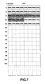
- FAT as table for carrying out management of file for recording computer data as shown in FIG. 7 is formed at a predetermined track of the data recording area on mini-disc 1.
- FAT is recorded into the leading cluster 16 of the area for recording computer data of cluster 16 to cluster 27 (It is of course that FAT may be recorded into, e.g., U-TOC area).
- (02h) is described at LOFAT in order that recording position of FAT can be seen.
- One block of FAT consists of 2 bytes. Respective blocks correspond to the area of predetermined size (e.g., cluster) of the data recording area. Namely, in the example shown in FIG. 6, since segment from clusters 16 to 27 in the data recording area is designated as computer data recording area, (FFEh) indicating available unused block is described in blocks 17 to 27 corresponding to these clusters 16 to 27. It is to be noted that when FAT is recorded in cluster 16, (FFDh) is recorded in block 16 of FAT corresponding to this cluster. This indicates that data is recorded at that portion (corresponding cluster 16), and that data terminates at that portion (corresponding cluster 16).
- FFEh computer data recording area
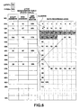
- FIG. 8 shows FAT in the state where computer data is recorded in a predetermined range of clusters 16 to 27 thus ensured.
- No. of block 18 is described in block 17 corresponding to cluster 17
- No. of block 19 is described in block 18
- No. of block 20 is described in block 19
- data (FFDh) indicating the last block of segment is described in block 20. Accordingly, it is seen that a series of computer data are recorded in the segment consisting of four clusters from cluster 17 to cluster 20.
- block No. 22 is described in block 21
- block No. 23 is described in block 22
- block No. 24 is described in block 23
- block No. 25 is described in block 24, and (FFDh) is described in block 25. Namely, a series of computer data are recorded in five clusters from cluster 21 to cluster 25.
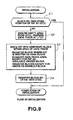
- FIG. 9 shows an example of processing carried out by host CPU 31 when mini-disc 1 (cartridge 1a) is loaded into body 41 of mini-disc device for carrying out recording/reproduction of computer data to instruct initialization.
- step S1 whether or not No. indicating parts table on a predetermined management table is described in LOFAT of U-TOC of mini-disc 1 is judged.
- No. of a predetermined pats table is described in LOFAT, since initialization for recording computer data has been already completed (recording area is ensured), initialization processing is completed.
- step S1 in the case where it is judged that a predetermined number is not described in LOFAT, the processing proceeds to step S2.
- empty area empty areas table
- predetermined 12 clusters (12 clusters from cluster 16 to cluster 27 in FIG. 6) are ensured as computer data recording track from empty areas in the data recording area (whether or not a corresponding area is an empty area can be recognized from P-TN01 ⁇ P-TNO 255 of U-TOC).
- this segment is registered into P-TN05, and its start address and its end address are registered into pars table (02h).
- step S3 FAT as shown in FIG. 7 is written into an arbitrary cluster (e.g., the leading cluster 16) of (12 clusters) within the area of data track ensured at step S2.
- data (FFDh) indicating used block and having no block to be linked is recorded into block 16 corresponding to cluster 16 into which FAT is written.
- data (FFEh) is recorded as available unused block into blocks 17 to 27 of FAT corresponding to clusters 17 to 27 where no FAT is recorded.
- data (FFFh) is recorded as disabled block into blocks of FAT corresponding to clusters except for the above.
- step S4 No. of parts table corresponding to cluster where FAT is recorded is described in LOFAT of U-TOC.
- FAT data is temporarily stored into memory 17, and is recorded into FAT on mini-disc 1 at a predetermined timing.
- FIG. 10 shows an example of processing executed by host CPU 31 in the case where computer data is recorded onto mini-disc 1.
- host CPU 31 reads in FAT that LOFAT of U-TOC indicates (FAT of cluster 16 of the data recording area of FIG. 6) recorded on mini-disc 1. This data is temporarily stored into memory 17, and CPU 31 reads in this data at a predetermined timing.
- step S12 At this step, whether or not there is available unused block in the entry of FAT which has been currently read in is judged. In the case of initially recording computer data, since available unused block exists, the processing proceeds from step S12 to step S15. At the step S15, one block (e.g., block 17 of FAT of FIG. 8) is selected from unused blocks. The block thus selected is caused to correspond to file into which data is to be written. Then, data is actually written into cluster to which that block corresponds (e.g., cluster 17 of the data recording area of FIG. 6).
- block 17 of FAT of FIG. 8 one block (e.g., block 17 of FAT of FIG. 8) is selected from unused blocks. The block thus selected is caused to correspond to file into which data is to be written. Then, data is actually written into cluster to which that block corresponds (e.g., cluster 17 of the data recording area of FIG. 6).
- step S16 the processing proceeds to step S16.
- step S18 whether or not writing of all data has been completed is judged. As a result, if such writing operation is not completed, the processing returns to step S12.
- step S16 it is judged at step S16 that block earlier allocated to the file exists. For this reason, in this case, the processing proceeds from step S16 to step S17 to register current block No. into entry of FAT of the former block. Namely, as explained with reference to FIG. 8, current block No. 18 is registered into, e.g., block 17. Similarly, block No. 19 is recorded into block 18 and block No. 20 is recorded into block 19.
- step S12 In the case where the ensured area is filled as the result of repetition of the above-mentioned operation and it is judged at step S12 that available unused block dose not exist in entry of FAT, i.e., when there is no empty area for recording computer data, the processing proceeds to step S13 to ensure an empty area of U-TOC to supplement that empty area as data track for recording computer data. Then, the processing proceeds to step S14 to register, as available unused block, block of area supplemented as data track into entry of FAT. Namely, processing similar to steps S2, S3 in the initialization processing of FIG. 9 is carried out to newly ensure (supplement) data recording area of 12 clusters. It is to be noted that since FAT has been already prepared, only data corresponding thereto is updated without newly preparing FAT.
- step S18 In the case where it is judged at step S18 that writing of all data has been completed, the processing proceeds to step S19 to register FAT entry of current block as the last block to update FAT. Namely, as in the case of block 20 of FAT of FIG. 8, data (FFDh) is recorded into the block.
- a quantity of allocation of one block of FAT serves as unit of data recording. As described above, if this quantity of allocation is 64 k bytes (1 cluster), writing similar to that of the ordinary mini-disc can be carried out. However, when an attempt is made to sufficiently transfer computer data, it is preferable that the quantity of allocation is about 8 k bytes smaller than 64 k bytes. In addition, when such a scheme is employed, recording of data can be made in a unit smaller than cluster.
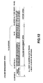
- FIG. 11 shows a recording format of writable mini-disc 1 in the case where this embodiment is realized.
- Lead-in area and Lead-out area are respectively provided.
- TOC (Table of Contents) data, etc. is recorded as occasion demands into the Lead-in area and the Lead-out area. General user cannot record information into these areas.
- the area except for Lead-in area and Lead-out area of information area is caused to be recordable area, and general user can record data into the recordable area or reproduce it therefrom.
- UTOC User TOC
- program area is provided on the innermost circumferential side of the recordable area.
- program area is provided on the innermost circumferential side of the recordable area.
- program area is provided into the UTOC area.
- audio data, data processed in computer, or other data can be recorded.
- audio tracks Trk2-1 and Trk4-1 are respectively comprised of one parts, and audio data are recorded thereinto.
- track Trk3 consisting of parts Trk3-1 to 3-3 is formed, and data processed by host CPU 31 is recorded thereonto.
- EFM ⁇ CIRC encoder/decoder 8 carries out processing so that data is recorded and reproduced with cluster (64 k bytes) being as unit with respect to respective tracks of the program area.
- Data track consists of Volume Management Area and Extent Area.
- Volume Management Area is formed at the leading portion of data track initially formed in the program area.
- Extent Area is caused to be an area except for the above.
- the former is caused to have 2 k bytes, and the latter is caused to have any one (e.g., 8 k bytes) of 4 k bytes, 8 k bytes, 16 k bytes, 32 k bytes and 64 k bytes.
- Volume Management Area consists of 16 clusters as shown in FIG. 12. Before one cluster of Volume Management Area, Boot Cluster is allocated as occasion demands.
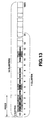
- FIG. 13 shows a format of the Volume Management Area.
- This Volume Management Area consists of 16 clusters and one cluster consists of 64 k bytes. For this reason, 1024 blocks of 2 k bytes are formed in the Volume Management Area.
- VD Volume Descriptor
- this Volume Descriptor e.g., number of blocks where root directory is recorded (any one of 0 to 1023 (4 in the case of this example)) and/or position information of volume space bit map, etc. are recorded.
- VVSB Volume Space Bitmap
- bitmap indicating the use state of the entirety of mini-disc 1 is recorded. This bitmap will be described later.
- MT Management Table
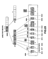
- FIG. 14 shows, in a model form, Management Table consisting of two blocks of No. 2 and No. 3. As shown in the figure, respective blocks having capacity (volume) of 4 bytes indicated by numbers 0 to 1023 correspond to block of 2k bytes indicated by numbers of blocks of 0 to 1023 in FIG. 13. In FIG. 13, since blocks of numbers 0 to 3 are prescribed in advance by standardization requirement, data is not particularly recorded (is caused to be reserved) in the corresponding area (block) on the Management Table of FIG. 14.
- DRB Directory Records Blocks
- ERP Extent Records Blocks
- Directory Records Block DRB the following information (directory management information and file management information) are recorded:
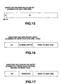
- the format shown in FIG. 15 indicates format in the case where Directory Records Block Entry consists of only one DRB.
- O is set to the first bit 31 of data of 4 bytes, and ID is recorded in the remaining 31 bits from bit 30 to bit 0.
- Directory Record Block Entry corresponding to block of number 4 of FIG. 14 is constituted with this format.
- 00000002 is recorded as ID. This ID indicates route directory.
- Directory Records Block DRB consists of a plurality of blocks
- the first directory records block entry is constituted with format as shown in FIG. 16
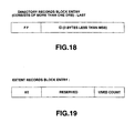
- the last entry is constituted with format as shown in FIG. 18, and the entry therebetween is constituted with format as shown in FIG. 17.
- FO is recorded into the first 1 byte
- ID of 1 bite on the MSB side of ID of 4 bytes is recorded into the next 1 byte.
- Index to Next DRB is allocated to the next 2 bytes.
- FE is allocated to the first 1 byte and the next 1 byte is reserved (unused).
- Index to Next DRB is allocated to the remaining two bytes.
- FF is allocated to the first 1 byte, and ID of the remaining 3 bytes except for MSB of 1 byte recorded at the second byte of FIG. 16 is recorded at the remaining 3 bytes.
- Entries indicated by No. 7, No. 8 and No. 10 of FIG. 14 are prescribed by the format shown in FIG. 16, 17 or 18.
- 0008 is recorded into the last 2 bytes of the entry corresponding to block No. 7. This indicates that the next DRB where related data is recorded is Directory Records Block DRB indicated by No. 8.
- OOOA hexadecimal number
- OOOA hexadecimal number
- FIG. 19 shows format of Extent Records Block Entry of the Management Table of FIG. 14.
- 80 is allocated to the first 1 byte, the remaining two bytes are reserved (unused), and Used Count is allocated to the last 1 byte. This used count indicates the number of used extent records of records corresponding to numbers of 0 to 63 of Extent Records Blocks of FIG. 20 which will be described later.
- entry corresponding to the block indicated by No. 5 is represented by the format of Extent Records Block Entry shown in FIG. 19. Value of 04 is recorded at the last 1 byte. This indicates that the number of used Extent Records Blocks of Extent Records ER indicated by 64 numbers of 0 to 63 of the Extent Records Blocks shown in FIG. 20 is 4 (respective Extent Records of Nos. 0, 1, 2, 4 have been already used).
- Extent Records Block ERB shown in FIG. 13 is constructed as shown in FIG. 20, for example. As shown in this figure, respective Extent Records Blocks ERB of 2 k bytes consist of 64 Extent Records ER indicated by No. 0 to No. 63 each having 32 bytes.
- Respective Extent Records ER consist of set of data of 4 bytes in which FFFF is recorded at the first 1 byte and seven Extent Record Indexes shown in FIG. 21, or consist of set of eight Extent Descriptors of 4 bytes shown in FIG. 22.
- Logical Block Offset is allocated to the first 2 bytes of Extent Records Index, Index to ERB is allocated to the next 2 bytes, and Offset of ER is allocated to the last 1 byte.
- Logical Block Offset indicates logical position from the lading portion within file of data indicated by index.
- Index to ERB is of a structure of 10 bits.
- Index to Extent Records Block ERB is indicated by any one of numbers 0 to 1023.
- Offset of ER is of a structure of 6 bits, and indicates any one of 64 Extent Records of Extent Records Block shown in FIG. 20.
- Extent Start Location is allocated to the first 2 bytes of extent descriptor, and Number of Blocks is allocated to the remaining 2 bytes.
- This Extent Start Location indicates start position of file recorded in the Extent Area.
- Number of Blocks indicates No. of blocks of file which starts from the start position.
- Extent Record of 32 bytes indicated by No. 1 indicates index.
- FFFF is recorded at the leading 2 bytes of the first 4 bytes.
- 0000 is allocated to the first 2 bytes of the next Extent Records Index as Logical Block Offset.
- 5 is stored as Index to ERB, and 2 is stored as Offset of ER.
- Offset of ER is 2 indicates that Extent Records indicated by No. 2 exists in FIG. 20. Its Logical Block Offset indicates 0000. This indicates that No. of the first block of file indicated in the Extent Records indicated by No. 2 is 0000 (i.e., the first block). In the Extent Records of No. 2, it is indicated that one block exists at the fifteenth block in terms of the absolute position (Extent Start Location) on data track at the leading portion (left side in the figure), for example.
- FIG. 23 shows, in a model form, the relationship between index and extent records recorded in the Extent Records Block.
- index of a predetermined Extent Records Block ERB is designated from directory record of a predetermined Directory Records Block (Index to ER). At the designated index, seven indexes at the maximum are recorded.
- start positions of 8 files at the maximum (Extent Start Location) and the numbers of blocks constituting those files (Nos. of Blocks) are recorded.
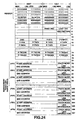
- U-TOC in this example is constructed as shown in FIG. 24, for example.
- LOFAT shown in FIG. 3 is not recorded at U-TOC of FIG. 24.
- Other formats of U-TOC are the same as the case shown in FIG. 3.
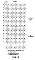
- bitmap as shown in FIG. 25 is used in place of FAT. This bitmap is recorded at VSB of FIG. 13.
- one entry of bitmap consists of 2 bits.
- respective entries corresponds to blocks of predetermined capacities (4 k bytes, 8 k bytes, 16 k bytes, 32 k bytes, or 64 k bytes) on mini-disc 1. Accordingly, the number of entries is formed by the number corresponding to the recording capacity of mini-disc 1.
- link information such as FFDh or No. of blocks to be linked is not recorded into the bitmap unlike FAT shown in FIGS. 7 and 8. Management of these information is carried out by the above-described directory information or file information (particularly Extent Records ER).
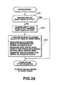
- FIG. 26 shows an example of processing executed by host CPU 31 when mini-disc 1 (cartridge 1a) is loaded into body 41 of mini-disc device for carrying out recording/reproduction of computer data to instruct initialization.
- step S31 whether or not data track is formed on mini-disc 1 is judged. Whether or not data track is formed can be discriminated from track mode of U-TOC. In the case where any data track exists, since initialization for recording computer data has been already completed (recording area is ensured), initialization processing has been completed.
- step S31 in the case where it is judged that no data track is formed, the processing proceeds to step S32.
- empty area empty areas table
- U-TOC data track is ensured.
- a predetermined number of blocks are ensured as data track for recording computer data from empty area in the program area (whether or not a corresponding area is empty area can be seen from P-TN01 ⁇ P-TN0255 of U-TOC).
- this area (parts table) is registered into, e.g., P-TNO5, and start address and end address of that area are registered into the parts table.
- data indicating that corresponding area is the area for recording computer data is registered into the area for track mode of the parts table.
- P-FRA of U-TOC is updated.
- the leading 16 clusters of the data track are caused to be VMA, and actual data is recorded into extent areas subsequent thereto (FIG. 12).
- bitmap is written into VSB (FIG. 13) of VMA (FIG. 12) consisting of the leading 16 clusters of the data track ensured at step S32.
- bitmap data is written as shown in FIG. 25.
- data (01) indicating used block is recorded into the entry corresponding to 16 clusters where VMA is written.
- Data (00) signifying available unused block is recorded into the entry of bitmap corresponding to 50 clusters (area for recording primary computer data) on the extent area.
- data (11) signifying disabled block is recorded into the entry of bitmap corresponding to block on the extent area except for the above.
- bitmap data is stored into memory 17 of FIG. 2, and is recorded into bitmap on mini-disc 1 at a predetermined timing.
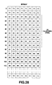
- FIG. 27 shows an example of processing executed by host CPU 31 in the case where computer data is recorded onto mini-disc 1.
- host CPU 31 reads in data of bitmap recorded on mini-disc 1.
- volume management area including data of bitmap is formed at the leading portion of data track initially formed in the program area.
- This bitmap data is temporarily stored into memory 17.
- host CPU 31 reads thereinto this data at a predetermined timing.
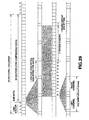
- step S42 the processing proceeds to step S42.
- step S45 one entry (e.g., entry 80 of bitmap of FIG. 28) is selected from unused blocks to allow this entry to correspond to file into which data is to be written. Then, data is actually written into block on the extent area to which that entry corresponds.
- step S46 data (01) indicating used area is recorded into the entry of bitmap corresponding to block of the extent area where recording is carried out (FIG. 28). Further, the processing proceeds to step S47 to register block of that extent area into the extent record ER (FIG. 13, FIG. 20).
- step S48 whether or not writing of all data is completed is judged. Unless such a writing is completed, the processing returns to step S42. An operation as described above will be repeated.
- step S42 In the case where ensured area is filled with data as the result of repetition of the above-described operation, and it is judged at step S42 that entry indicating available unused block does not exist in the bitmap, i.e., when there is no empty area for recording computer data, the processing proceeds to step S43 to ensure empty area of U-TOC to supplement that empty area as data track for recording computer data. Then, the processing proceeds to step S44 to register block of the supplemented area of the data track as available unused block. Namely, processing similar to those at steps S32, S33 in the initialization processing of FIG. 26 is carried out to newly ensure (supplement) data recording area of 12 blocks. It is to be noted that the number of blocks supplemented at this time is arbitrary. In this case, however, since bitmap has been already prepared, only data corresponding thereto is updated without newly preparing such bitmap.
- step S48 In the case where it is judged at step S48 that writing of all data has been completed, the processing is completed.
- unit for carrying out management by FAT or bitmap is a value smaller than one cluster
- body 41 in order to record data with respect to one unit, body 41 once reads out data of one cluster including that unit from mini-disc 1 to store it into RAM 13. Then, data corresponding to that unit is transferred from host CPU 31, and is then newly stored into RAM 13. Then, data of one cluster which has been read out from RAM 13 is written into mini-disc 1. Namely, recording in a unit substantially smaller than one cluster can be made. On the other hand, reproduction is carried out in sector unit.
- a scheme is employed to designate a predetermined range from the range of recording medium caused to undergo management in accordance with first table to carry out management of recording state onto recording medium of digital data having second unit as reference in accordance with second table. Accordingly, it is possible to ensure compatibility with recording medium on which digital data is recorded with the first unit being as reference. Further, if there is any empty area in the recording medium, it is possible to supplement digital data in the area to record it.
- the second unit is caused to be smaller than the first unit, it is possible to record data in a processing unit smaller than a processing unit set in advance.
- a scheme is employed to register one large track into the first table to partition this track into much more plural areas on the second table so that there are provided partitions more than partitionable numbers in the first table (255 of P-TN01 to P-TN0255 in the case of the above-mentioned embodiment), thus making it possible to record data.
Landscapes
- Engineering & Computer Science (AREA)
- Databases & Information Systems (AREA)
- Theoretical Computer Science (AREA)
- General Engineering & Computer Science (AREA)
- General Physics & Mathematics (AREA)
- Software Systems (AREA)
- Data Mining & Analysis (AREA)
- Physics & Mathematics (AREA)
- Signal Processing (AREA)
- Multimedia (AREA)
- Management Or Editing Of Information On Record Carriers (AREA)
- Signal Processing For Digital Recording And Reproducing (AREA)
- Color Printing (AREA)
- Control Of Heat Treatment Processes (AREA)
- Information Retrieval, Db Structures And Fs Structures Therefor (AREA)
- Heating, Cooling, Or Curing Plastics Or The Like In General (AREA)
Claims (30)
- Aufzeichnungsträger-Verwaltungsverfahren zur Durchführung der Verwaltung bzw. des Managements der Aufzeichnung von digitalen Daten in bezug auf einen Aufzeichnungsträger (1), wobei die Verwaltung der Aufzeichnung der digitalen Daten auf dem betreffenden Aufzeichnungsträger, auf dem eine Aufzeichnung in ersten Datenaufzeichnungseinheiten (CLUSTER) ausgeführt wird, entsprechend einer ersten Tabelle (Verwaltungstabelle) ausgeführt wird,
dadurch gekennzeichnet,dass in einem bestimmten Bereich des betreffenden Aufzeichnungsträgers (1), der eine Verwaltung entsprechend der genannten ersten Tabelle erfährt, digitale Daten in zweiten Datenaufzeichnungseinheiten (BLOCK) aufzuzeichnen sind,dass die Verwaltung der Aufzeichnung der digitalen Daten . auf dem betreffenden Aufzeichnungsträger (1) in dem genannten bestimmten Bereich, in welchem eine Aufzeichnung in zweiten Dateneinheiten durchgeführt wird, entsprechend einer zweiten Tabelle (FAT; BITMAP) vorgenommen wirdund dass Daten entsprechend den betreffenden zweiten Datenaufzeichnungseinheiten in der genannten zweiten Tabelle gebildet werden, die Informationen enthält, welche angeben, ob digitale Daten bereits in den entsprechenden zweiten Datenaufzeichnungseinheiten des genannten Aufzeichnungsträgers (1) aufgezeichnet worden sind oder nicht. - Aufzeichnungsträger-Verwaltungsverfahren nach Anspruch 1, wobei die zweite Datenaufzeichnungseinheit (BLOC) kleiner ist als die erste Datenaufzeichnungseinheit (CLUSTER).
- Aufzeichnungsträger-Verwaltungsverfahren nach Anspruch 1 oder 2, wobei die genannte erste Datenaufzeichnungseinheit ein Cluster ist und wobei die genannte zweite Datenaufzeichnungseinheit ein Block ist.
- Aufzeichnungsträger-Verwaltungsverfahren nach Anspruch 1, wobei die zweite Datenaufzeichnungseinheit von derselben Größe ist wie jene der ersten Datenaufzeichnungseinheit.
- Aufzeichnungsträger-Verwaltungsverfahren nach einem der Ansprüche 1 bis 4, wobei die erste Tabelle in U-TOC oder TOC des Aufzeichnungsträgers (1) aufgezeichnet wird und wobei die zweite Tabelle in dem Bereich aufgezeichnet wird, der veranlaßt wird, eine Verwaltung durch die zweite Tabelle des Aufzeichnungsträgers (1) zu erfahren.
- Aufzeichnungsträger-Verwaltungsverfahren nach Anspruch 5, wobei ein auf die Aufzeichnungsposition der zweiten Tabelle (FAT; BITMAP) hinweisender Zeiger in U-TOC oder TOC aufgezeichnet wird.
- Aufzeichnungsträger-Verwaltungsverfahren nach einem der Ansprüche 1 bis 6, wobei unterschiedliche Arten von digitalen Daten in dem Bereich, der veranlaßt wird, eine Verwaltung durch die erste Tabelle zu erfahren, und in dem Bereich aufgezeichnet werden, der veranlaßt wird, eine Verwaltung durch die zweite Tabelle zu erfahren.
- Aufzeichnungsträger-Verwaltungsverfahren nach Anspruch 7, wobei digitale Audiodaten in dem Bereich aufgezeichnet werden, der veranlaßt wird, eine Verwaltung lediglich durch die erste Tabelle zu erfahren,
und wobei durch einen Computer verarbeitete digitale Daten in dem Bereich aufgezeichnet werden, der veranlaßt wird, eine Verwaltung durch die zweite Tabelle zu erfahren. - Aufzeichnungsträger-Verwaltungsverfahren nach einem der Ansprüche 1 bis 8, wobei Daten, die den betreffenden zweiten Datenaufzeichnungseinheiten (BLOCK) entsprechen, in der zweiten Tabelle (FAT; BITMAP) gebildet werden.
- Aufzeichnungsträger-Verwaltungsverfahren nach Anspruch 9, wobei Daten, die den betreffenden zweiten Datenaufzeichnungseinheiten entsprechen, eine Information enthalten, welche anzeigt, dass digitale Daten in den entsprechenden zweiten Datenaufzeichnungseinheiten des Aufzeichnungsträgers (1) bereits verwendet worden sind.
- Aufzeichnungsträger-Verwaltungsverfahren nach Anspruch 9, wobei Daten, die den betreffenden zweiten Datenaufzeichnungseinheiten entsprechen, eine Information enthalten, die anzeigt, dass die entsprechenden zweiten Datenaufzeichnungseinheiten des Aufzeichnungsträgers (1) unwirksam gemacht sind.
- Aufzeichnungsträger-Verwaltungsverfahren nach Anspruch 9, wobei Daten, die den betreffenden zweiten Datenaufzeichnungseinheiten entsprechen, eine Information enthalten, die anzeigt, dass die entsprechenden zweiten Datenaufzeichnungseinheiten des Aufzeichnungsträgers (1) fehlerhaft sind.
- Aufzeichnungsträger-Verwaltungsverfahren nach Anspruch 10, 11 oder 12, wobei ferner eine Kettungsinformation innerhalb der zweiten Tabelle in der zweiten Tabelle aufgezeichnet wird.
- Aufzeichnungsträger-Verwaltungsverfahren nach einem der Ansprüche 1 bis 13, wobei in dem Fall, dass ein aufzeichnungsfreier Bereich in irgendeinem Bereich; der den Bereich, in welchem eine Aufzeichnung in ersten Datenaufzeichnungseinheiten ausgeführt wird, und den Bereich, in welchem eine Aufzeichnung in zweiten Datenaufzeichnungseinheiten ausgeführt wird, umfasst, unzureichend ist, der betreffende andere Bereich in den genannten einen Bereich in der ersten oder zweiten Tabelle geändert wird.
- Aufzeichnungsträger-Verwaltungsverfahren nach Anspruch 5, wobei die U-TOC- oder TOC-Angabe in einem festliegenden Bereich des Aufzeichnungsträgers (1) aufgezeichnet wird.
- Aufzeichnungsträger-Verwaltungsverfahren nach Anspruch 5, wobei die genannte zweite Tabelle ein Bitmap ist.
- Aufzeichnungsträger-Verwaltungsverfahren nach Anspruch 5, wobei die Information, welche die Position der zweiten Tabelle anzeigt, unmittelbar vor der zweiten Tabelle aufgezeichnet wird.
- Aufzeichnungsträger-Verwaltungsverfahren nach einem der vorhergehenden Ansprüche, umfassend ferner die Schritte:Ermitteln (S31) eines Leerbereiches des Aufzeichnungsträgers (1) aus Daten der genannten ersten Tabelle,Aufzeichnen von Daten in der ersten Tabelle, die anzeigen, dass der Leerbereich veranlaßt wird, als Spuren für digitale Daten zu dienen,und Bereitstellen (S33) der genannten zweiten Tabelle, die den Nutzungszustand von Daten des Aufzeichnungsträgers (1) im Anfangsteil des Leerbereiches anzeigt, der veranlaßt wird, als Spuren für digitale Daten zu dienen.
- Aufzeichnungsträger-Verwaltungsverfahren nach Anspruch 18, wobei eine Entscheidung darüber, ob irgendeine Spur für digitale Daten bereits existiert oder nicht, aus Daten der betreffenden ersten Tabelle getroffen wird.
- Aufzeichnungsträger-Verwaltungsverfahren nach Anspruch 18, wobei eine Information, welche die Position der zweiten Tabelle anzeigt, unmittelbar vor der betreffenden zweiten Tabelle aufgezeichnet wird.
- Aufzeichnungsträger-Verwaltungsverfahren nach Anspruch 18, wobei die zweite Tabelle ein Bitmap ist, das eine Information enthält, welche anzeigt, dass die zweite Datenaufzeichnungseinheit verfügbar ist.
- Aufzeichnungsträger-Verwaltungsverfahren nach Anspruch 18, wobei die zweite Tabelle ein Bitmap ist, das eine Information enthält, welche anzeigt, dass die zweite Datenaufzeichnungseinheit bereits verwendet worden ist.
- Aufzeichnungsträger-Verwaltungsverfahren nach Anspruch 18, wobei die zweite Tabelle ein Bitmap ist, das eine Information enthält, welche anzeigt, dass die zweite Datenaufzeichnungseinheit fehlerhaft ist.
- Aufzeichnungsträger-Verwaltungsverfahren nach Anspruch 18, wobei die zweite Tabelle ein Bitmap ist, das eine Information enthält, welche anzeigt, dass die zweite Datenaufzeichnungseinheit unwirksam gemacht ist.
- Aufzeichnungsträger-Verwaltungsverfahren nach einem der vorhergehenden Ansprüche, umfassend ferner die Verfahrensschritte:Auslesen der genannten zweiten Tabelle aus Spuren für digitale Daten des Aufzeichnungsträgers (1) auf der Grundlage von Daten der genannten ersten Tabelle,Ermitteln (S42) einer Information, die einen verfügbaren Block anzeigt, aus der zweiten Tabelle,Aufzeichnen von digitalen Daten in Blöcken der Spuren für digitale Daten entsprechend der den betreffenden verfügbaren Block anzeigenden Informationund Neuschreiben (S47) der den betreffenden verfügbaren Block der zweiten Tabelle anzeigenden Information in eine einen unwirksam gemachten Block anzeigende Information.
- Aufzeichnungsträger-Verwaltungsverfahren nach Anspruch 25, wobei das Verfahren in dem Fall, dass die einen verfügbaren Block anzeigende Information nicht in der zweiten Tabelle enthalten ist, die Schritte umfasst:Ermitteln (S43) eines Leerbereiches des Aufzeichnungsträgers (1) aus Daten der ersten Tabelle,Aufzeichnen von Daten, die angeben, dass der Leerbereich veranlaßt wird, Spuren für digitale Daten zu sein, in der ersten Tabelle,und Aufzeichnen (S47) einer einen verfügbaren Block anzeigenden Information in dem Bereich für Daten der zweiten Tabelle entsprechend dem Block des Leerbereiches, der veranlaßt wird, Spuren für digitale Daten zu sein.
- Aufzeichnungsträger-Verwaltungsverfahren nach Anspruch 25, umfassend die Verfahrensschritte des Auslesens einer die Position der zweiten Tabelle angebenden Information, welche unmittelbar vor der zweiten Tabelle aufgezeichnet ist, auf der Grundlage der ersten Tabelle,
und Auslesen der zweiten Tabelle auf der Grundlage einer die Position der zweiten Tabelle angebenden Information. - Aufzeichnungsträger-Verwaltungsverfahren nach Anspruch 24, ferner umfassend die Verfahrensschritte:Auslesen von digitalen Daten der ersten Datenaufzeichnungseinheiten von dem Aufzeichnungsträger (1), die veranlaßt werden, eine Verwaltung durch die erste Tabelle zu erfahren, Speichern der digitalen Daten der ersten Datenaufzeichnungseinheiten in einem Speicher (16),Aktualisieren zumindest eines Teiles der digitalen Daten der ersten Datenaufzeichnungseinheiten, die in dem genannten Speicher (16) gespeichert sind, durch neue digitale Daten jeder zweiten Einheit weniger als durch die erste Einheit, welche veranlaßt wird, eine Verwaltung durch die zweite Tabelle zu erfahren,und Aufzeichnen von neuen digitalen Daten der ersten Einheiten, welche die in dem genannten Speicher (16) gespeicherten neuen digitalen Daten enthalten, auf dem Aufzeichnungsträger (1).
- System zur Aufzeichnung und/oder Wiedergabe von digitalen Daten auf bzw. von einem Aufzeichnungsträger (1) gemäß dem Verfahren nach einem der Ansprüche 1 bis 28, umfassend Aufzeichnungseinrichtungen (3-6) zur Aufzeichnung einer ersten Tabelle (Verwaltungstabelle) für die Verwaltung von digitalen Daten, die in einem bestimmten Bereich in ersten Datenaufzeichnungseinheiten (CLUSTER) aufgezeichnet sind, einer zweiten Tabelle (FAT; BITMAP) zur Verwaltung von digitalen Daten in dem betreffenden bestimmten Bereich, die in zweiten Datenaufzeichnungseinheiten (BLOCK) aufgezeichnet sind und die eine Information darüber enthalten, ob digitale Daten in den entsprechenden zweiten Datenaufzeichnungseinheiten bereits aufgezeichnet worden sind oder nicht,
und der digitalen Daten auf dem Aufzeichnungsträger (1), Wiedergabeeinrichtungen (3-6) zur Wiedergabe der auf dem Aufzeichnungsträger (1) aufgezeichneten ersten Tabelle, zweiten Tabelle und der genannten digitalen Daten, Speichereinrichtungen (16, 17) zur Speicherung der genannten ersten Tabelle und der genannten zweiten Tabelle
und Steuereinrichtungen (11, 12) zur Steuerung der Aufzeichnungs- und/oder Wiedergabeeinrichtungen (3-6) entsprechend den genannten ersten und zweiten Tabellen. - Aufzeichnungsträger, auf dem eine erste Tabelle (Verwaltungstabelle) für die Verwaltung von digitalen Daten, die in einem bestimmten Bereich in ersten Datenaufzeichnungseinheiten (CLUSTER) aufgezeichnet sind,
eine zweite Tabelle (FAT; BITMAP) zur Verwaltung von digitalen Daten in dem betreffenden bestimmten Bereich, die in zweiten Datenaufzeichnungseinheiten (BLOCK) aufgezeichnet sind und die eine Information darüber enthalten, ob digitale Daten in den entsprechenden zweiten Datenaufzeichnungseinheiten bereits aufgezeichnet worden sind oder nicht,
und digitale Daten aufgezeichnet sind, wobei die betreffenden Tabellen und die genannten Daten alle entsprechend dem Verwaltungsverfahren nach einem der Ansprüche 1 bis 28 aufgezeichnet sind.
Applications Claiming Priority (7)
| Application Number | Priority Date | Filing Date | Title |
|---|---|---|---|
| JP141819/93 | 1993-06-14 | ||
| JP14181993 | 1993-06-14 | ||
| JP14181993 | 1993-06-14 | ||
| JP27009993 | 1993-10-28 | ||
| JP27009993 | 1993-10-28 | ||
| JP270099/93 | 1993-10-28 | ||
| PCT/JP1994/000964 WO1994029867A1 (en) | 1993-06-14 | 1994-06-14 | Recording medium management method |
Publications (3)
| Publication Number | Publication Date |
|---|---|
| EP0655740A1 EP0655740A1 (de) | 1995-05-31 |
| EP0655740A4 EP0655740A4 (de) | 1996-09-11 |
| EP0655740B1 true EP0655740B1 (de) | 2003-01-08 |
Family
ID=26473989
Family Applications (1)
| Application Number | Title | Priority Date | Filing Date |
|---|---|---|---|
| EP94917813A Expired - Lifetime EP0655740B1 (de) | 1993-06-14 | 1994-06-14 | Verwaltungsverfahren für ein aufzeichnungsmedium |
Country Status (14)
| Country | Link |
|---|---|
| US (5) | US5838666A (de) |
| EP (1) | EP0655740B1 (de) |
| KR (1) | KR100299400B1 (de) |
| CN (1) | CN1112380A (de) |
| AT (1) | ATE230892T1 (de) |
| AU (1) | AU676063B2 (de) |
| BR (1) | BR9405407A (de) |
| CA (1) | CA2141044C (de) |
| DE (1) | DE69431979T2 (de) |
| ES (1) | ES2185653T3 (de) |
| PL (1) | PL173555B1 (de) |
| RU (1) | RU2180140C2 (de) |
| TW (1) | TW239209B (de) |
| WO (1) | WO1994029867A1 (de) |
Families Citing this family (67)
| Publication number | Priority date | Publication date | Assignee | Title |
|---|---|---|---|---|
| JPH0845246A (ja) * | 1994-07-29 | 1996-02-16 | Sony Corp | 記録媒体、再生方法、記録装置、及び再生装置 |
| US5740435A (en) * | 1994-10-31 | 1998-04-14 | Sony Corporation | Data management apparatus and method for managing data of variable lengths recorded on a record medium |
| JP3901748B2 (ja) * | 1995-01-30 | 2007-04-04 | ソニー株式会社 | ディスク状記録媒体及びその記録装置並びに再生装置 |
| JP3493822B2 (ja) * | 1995-08-04 | 2004-02-03 | ソニー株式会社 | データ記録方法及び装置、並びに、データ再生方法及び装置 |
| GB2312059B (en) * | 1996-04-12 | 2000-11-15 | Sony Uk Ltd | Data storage |
| US6741796B1 (en) * | 1997-03-25 | 2004-05-25 | Samsung Electronics, Co., Ltd. | DVD-Audio disk, and apparatus and method for playing the same |
| US7110662B1 (en) | 1997-03-25 | 2006-09-19 | Samsung Electronics Co., Ltd. | Apparatus and method for recording data on a DVD-audio disk |
| JPH1145548A (ja) * | 1997-05-29 | 1999-02-16 | Sony Corp | オーディオデータの記録方法、記録装置、伝送方法 |
| JPH1166824A (ja) * | 1997-08-15 | 1999-03-09 | Sony Corp | オーディオサーバシステム |
| EP1213722A3 (de) * | 1997-09-17 | 2005-03-09 | Matsushita Electric Industrial Co., Ltd. | Aufzeichnungsgerät für optische Platte, computerlesbares Aufzeichnungsmedium zur Aufzeichnung eines Datenverwaltungsprogramms sowie optische Platte |
| US6370325B2 (en) | 1997-09-17 | 2002-04-09 | Matsushita Electric Industrial Co., Ltd. | Optical disc recording apparatus, computer-readable recording medium recording a file management program, and optical disc |
| JPH11110923A (ja) * | 1997-09-30 | 1999-04-23 | Mitsumi Electric Co Ltd | 光ディスク装置および光ディスク装置の検査方法 |
| DK0956558T3 (da) * | 1997-11-29 | 2006-03-20 | Koninkl Philips Electronics Nv | Fremgangsmåde og indretning til lagring af audiocentreret information ved hjælp af en indholdsfortegnelsesmekanisme (TOC-mekanisme) og tillige ved hjælp af en filbaseret adgangsmekanisme gennem et root directory, der indeholder... |
| KR100505576B1 (ko) | 1997-12-31 | 2005-09-26 | 삼성전자주식회사 | 모델에 따른 테이블 정보가 기록된 하드디스크를 구비한 하드디스크 드라이브 |
| KR100588443B1 (ko) | 1998-02-03 | 2006-06-13 | 산요덴키가부시키가이샤 | 정보 기록 장치, 정보 기록 방법 및 기록 매체 |
| US6175900B1 (en) | 1998-02-09 | 2001-01-16 | Microsoft Corporation | Hierarchical bitmap-based memory manager |
| JPH11259980A (ja) * | 1998-03-09 | 1999-09-24 | Pioneer Electron Corp | 情報記録装置 |
| US6192014B1 (en) * | 1998-06-05 | 2001-02-20 | Winbond Electronics Corporation | Playback method and apparatus for reading interleaved audio programs recorded on a record carrier |
| KR100601598B1 (ko) * | 1998-06-15 | 2006-07-14 | 삼성전자주식회사 | 기록 방지 정보를 저장하는 기록 매체와 기록 방지 방법 |
| US6744713B1 (en) | 1998-06-15 | 2004-06-01 | Samsung Electronics Co., Ltd. | Recording medium for storing write protection information and write protection method thereof |
| US6788631B1 (en) * | 1998-09-02 | 2004-09-07 | Lc Electronics Inc. | Optical recording medium having recording capacity information and method for indicating recording capacity |
| US7389038B1 (en) | 1998-09-09 | 2008-06-17 | Sharp Kabushiki Kaisha | Multimedia information recording device and method for recording multimedia information file on recording medium |
| US7050701B1 (en) * | 1998-09-25 | 2006-05-23 | Matsushita Electric Industrial Co., Ltd. | Information recording medium, information recording/reproducing method, and information recording/reproducing device |
| JP3511916B2 (ja) * | 1998-11-17 | 2004-03-29 | 松下電器産業株式会社 | 記録再生装置 |
| KR100704998B1 (ko) * | 1999-02-26 | 2007-04-09 | 소니 가부시끼 가이샤 | 기록방법, 관리방법 및 기록장치 |
| US6393517B1 (en) * | 1999-08-31 | 2002-05-21 | Sony Corporation | SCSI port filter driver for enhanced audio data |
| JP3785299B2 (ja) * | 2000-03-16 | 2006-06-14 | 本田技研工業株式会社 | 車両制御装置のためのメモリ書き換えシステム |
| US6574642B1 (en) * | 2000-03-30 | 2003-06-03 | Roxio, Inc. | Methods for processing data transferred to system memory in preparation for recording to an optical disc |
| US7151729B1 (en) * | 2000-06-29 | 2006-12-19 | Samsung Electronics Co., Ltd. | Optical recording medium having read-only storage area and writeable storage area and recording/reproducing apparatus and method therefor |
| KR100364576B1 (ko) * | 2000-07-28 | 2002-12-16 | 주식회사 엘지이아이 | 부가정보를 포함한 데이터 저장 및 재생방법 |
| JP4304888B2 (ja) * | 2000-09-04 | 2009-07-29 | ソニー株式会社 | 記録媒体、編集装置及び編集方法 |
| US20080123491A1 (en) * | 2000-09-07 | 2008-05-29 | Samsung Electronics Co., Ltd | Optical recording medium having read-only storage area and writeable storage area and recording/reproducing apparatus and method therefor |
| JP4784030B2 (ja) * | 2001-09-21 | 2011-09-28 | ソニー株式会社 | 記録装置、再生装置、記録方法、再生方法 |
| US7243108B1 (en) * | 2001-10-14 | 2007-07-10 | Frank Jas | Database component packet manager |
| JP2003223763A (ja) * | 2001-11-20 | 2003-08-08 | Ricoh Co Ltd | 情報記録再生装置、情報記録再生ユニット、情報記録再生方法、プログラム及び記憶媒体 |
| AU2003202530A1 (en) * | 2002-04-01 | 2003-10-16 | Sony Corporation | Reproducing method, reproducing apparatus, recording method, and recording apparatus |
| AU2003201840A1 (en) * | 2002-04-01 | 2003-10-23 | Sony Corporation | Reproducing method, reproducing apparatus, recording method, recording apparatus, and method for generating a management table |
| AU2003201833A1 (en) * | 2002-04-01 | 2003-10-23 | Sony Corporation | Storage medium initialization and cancellation method |
| ZA200302362B (en) * | 2002-04-01 | 2003-10-01 | Sony Corp | Reproducing method, reproducing apparatus, recording method, and recording apparatus. |
| RU2303822C2 (ru) * | 2002-04-01 | 2007-07-27 | Сони Корпорейшн | Способ записи данных на носитель записи |
| DE60304924T2 (de) * | 2002-04-01 | 2007-01-11 | Sony Corp. | Verfahren zum Initialisieren einer Minidisk sowie Aufzeichnungs- und Wiedergabeverfahren und Aufzeichnungs- und Wiedergabegerät |
| AU2003202528A1 (en) * | 2002-04-01 | 2003-10-23 | Sony Corporation | Track management method and apparatus for managing tracks on a storage medium |
| AU2003201838A1 (en) * | 2002-04-01 | 2003-10-23 | Sony Corporation | Reproducing method, reproducing apparatus, and data accessing method |
| JP3707685B2 (ja) * | 2002-05-08 | 2005-10-19 | ソニー株式会社 | 光ディスク装置、光ディスクの記録方法、光ディスクの記録方法のプログラム及び光ディスクの記録方法のプログラムを記録した記録媒体 |
| AU2003210026A1 (en) * | 2002-05-20 | 2003-12-02 | Samsung Electronics Co., Ltd. | Method of recording drive information on optical disc and optical disc having drive information recorded using the method |
| EP1506545B1 (de) * | 2002-05-20 | 2008-05-28 | Samsung Electronics Co., Ltd. | Optischer datenträger und verfahren zum aufzeichnen von daten auf diesem |
| KR100881665B1 (ko) * | 2002-05-31 | 2009-02-06 | 삼성전자주식회사 | 다층의 광 정보 저장매체 및 그 기록/재생 방법 |
| JP3889672B2 (ja) * | 2002-06-19 | 2007-03-07 | 三洋電機株式会社 | データ記録再生装置 |
| AU2003241198B2 (en) * | 2002-06-21 | 2009-09-03 | Lg Electronics Inc. | Recording medium having data structure for managing reproduction of video data recorded thereon |
| KR100667746B1 (ko) * | 2002-07-15 | 2007-01-11 | 삼성전자주식회사 | 드라이브 정보가 기록된 정보저장 매체 및 그 기록 방법 |
| JP4036056B2 (ja) * | 2002-08-13 | 2008-01-23 | ソニー株式会社 | 記録装置および方法、記録媒体、並びにプログラム |
| TWI221604B (en) * | 2002-09-10 | 2004-10-01 | Mediatek Inc | Defect detection circuit for optical recording medium and method of the same |
| US7174420B2 (en) * | 2002-10-22 | 2007-02-06 | Microsoft Corporation | Transaction-safe FAT file system |
| US7363540B2 (en) | 2002-10-22 | 2008-04-22 | Microsoft Corporation | Transaction-safe FAT file system improvements |
| US20040246824A1 (en) * | 2003-06-09 | 2004-12-09 | Media Tek Inc. | Method for reading table of content of multi-session optical medium |
| KR20050027787A (ko) * | 2003-09-16 | 2005-03-21 | 삼성전자주식회사 | 데이터 기록 상태 정보를 제공하는 광 디스크 |
| CN100342374C (zh) * | 2003-12-24 | 2007-10-10 | 华为技术有限公司 | 一种数据存储方法及装置 |
| KR100607985B1 (ko) | 2004-06-12 | 2006-08-02 | 삼성전자주식회사 | 기록/재생 장치 및 그 정보 저장 매체 |
| US20060104615A1 (en) * | 2004-11-12 | 2006-05-18 | Kun-Da Wu | Recording medium, method for storing and reproducing digital image medium data on the recording medium |
| US7873596B2 (en) | 2006-05-23 | 2011-01-18 | Microsoft Corporation | Extending cluster allocations in an extensible file system |
| US9639554B2 (en) | 2004-12-17 | 2017-05-02 | Microsoft Technology Licensing, Llc | Extensible file system |
| US8606830B2 (en) | 2004-12-17 | 2013-12-10 | Microsoft Corporation | Contiguous file allocation in an extensible file system |
| US8321439B2 (en) | 2004-12-17 | 2012-11-27 | Microsoft Corporation | Quick filename lookup using name hash |
| JP4556813B2 (ja) | 2005-09-08 | 2010-10-06 | カシオ計算機株式会社 | 画像処理装置、及びプログラム |
| JP2007074578A (ja) | 2005-09-08 | 2007-03-22 | Casio Comput Co Ltd | 画像処理装置、撮影装置、及びプログラム |
| US7613738B2 (en) | 2007-01-16 | 2009-11-03 | Microsoft Corporation | FAT directory structure for use in transaction safe file system |
| US7747664B2 (en) * | 2007-01-16 | 2010-06-29 | Microsoft Corporation | Storage system format for transaction safe file system |
Family Cites Families (24)
| Publication number | Priority date | Publication date | Assignee | Title |
|---|---|---|---|---|
| JPS6459689A (en) * | 1987-08-31 | 1989-03-07 | Matsushita Electric Industrial Co Ltd | Information recording and reproducing device |
| JP2656524B2 (ja) * | 1988-01-20 | 1997-09-24 | 株式会社日立製作所 | データ格納方法および装置 |
| GB2218833A (en) * | 1988-05-16 | 1989-11-22 | Ardent Computer Corp | File system |
| GB2219886A (en) * | 1988-06-15 | 1989-12-20 | Philips Nv | Recording and playback apparatus |
| SU1594547A1 (ru) * | 1988-09-26 | 1990-09-23 | Войсковая Часть 32103 | Устройство дл адресации блоков пам ти |
| KR930006580B1 (ko) * | 1989-05-26 | 1993-07-21 | 샤프 가부시끼가이샤 | 기록재생장치 |
| SU1716524A1 (ru) * | 1990-02-05 | 1992-02-28 | Военная академия им.Ф.Э.Дзержинского | Устройство дл распределени пам ти |
| US5434991A (en) * | 1990-03-20 | 1995-07-18 | Sharp Kabushiki Kaisha | Method and apparatus for recording and reproducing information in black on a rewritable recording medium |
| JPH0467320A (ja) * | 1990-07-02 | 1992-03-03 | Hitachi Ltd | 情報記録ディスク |
| JP2888958B2 (ja) * | 1990-10-20 | 1999-05-10 | 富士通株式会社 | 部分書き換え可能な記憶媒体におけるファイル管理方式 |
| JP3180366B2 (ja) * | 1991-04-19 | 2001-06-25 | ソニー株式会社 | 記録再生装置及び記録再生方法 |
| JPH04364549A (ja) * | 1991-06-12 | 1992-12-16 | Hitachi Ltd | ファイル格納方式とアクセス方式 |
| JP3239388B2 (ja) * | 1991-09-27 | 2001-12-17 | ソニー株式会社 | デイスク記録装置、デイスク再生装置及び記録方法 |
| JP3163686B2 (ja) * | 1991-10-08 | 2001-05-08 | ソニー株式会社 | 再生装置 |
| JP3355649B2 (ja) * | 1992-05-20 | 2002-12-09 | ソニー株式会社 | 記録又は再生装置 |
| JP3130380B2 (ja) * | 1992-08-28 | 2001-01-31 | 株式会社ケンウッド | 光ディスク記録再生装置 |
| DE69332901T2 (de) * | 1992-09-03 | 2004-01-29 | Sony Corp | Datenaufzeichnungsgerät und -verfahren |
| JP3218743B2 (ja) * | 1992-10-16 | 2001-10-15 | ソニー株式会社 | 記録/再生装置、ディスク記録再生システム、及び記録方法 |
| JP3431030B2 (ja) * | 1992-11-12 | 2003-07-28 | ソニー株式会社 | 再生装置および再生方法 |
| JPH06203479A (ja) * | 1992-12-30 | 1994-07-22 | Sony Corp | 記録媒体及びナビゲーシヨンシステム |
| WO1994019800A1 (fr) * | 1993-02-22 | 1994-09-01 | Sony Corporation | Appareil a disque optique |
| US5687397A (en) * | 1993-02-26 | 1997-11-11 | Sony Corporation | System for expansion of data storage medium to store user data |
| JP3353382B2 (ja) * | 1993-04-23 | 2002-12-03 | ソニー株式会社 | 記録又は再生装置、及びメモリ制御装置 |
| JP3508168B2 (ja) * | 1993-07-07 | 2004-03-22 | ソニー株式会社 | 再生装置 |
-
1994
- 1994-06-14 CA CA002141044A patent/CA2141044C/en not_active Expired - Fee Related
- 1994-06-14 CN CN94190498A patent/CN1112380A/zh active Pending
- 1994-06-14 US US08/374,727 patent/US5838666A/en not_active Expired - Fee Related
- 1994-06-14 DE DE69431979T patent/DE69431979T2/de not_active Expired - Fee Related
- 1994-06-14 AT AT94917813T patent/ATE230892T1/de not_active IP Right Cessation
- 1994-06-14 PL PL94307475A patent/PL173555B1/pl unknown
- 1994-06-14 KR KR1019950700613A patent/KR100299400B1/ko not_active Expired - Fee Related
- 1994-06-14 AU AU69369/94A patent/AU676063B2/en not_active Ceased
- 1994-06-14 BR BR9405407-0A patent/BR9405407A/pt not_active IP Right Cessation
- 1994-06-14 WO PCT/JP1994/000964 patent/WO1994029867A1/ja not_active Ceased
- 1994-06-14 EP EP94917813A patent/EP0655740B1/de not_active Expired - Lifetime
- 1994-06-14 RU RU95106481/28A patent/RU2180140C2/ru not_active IP Right Cessation
- 1994-06-14 ES ES94917813T patent/ES2185653T3/es not_active Expired - Lifetime
- 1994-07-27 TW TW083106884A patent/TW239209B/zh active
-
1997
- 1997-05-12 US US08/854,496 patent/US5867466A/en not_active Expired - Fee Related
- 1997-05-12 US US08/854,839 patent/US5825734A/en not_active Expired - Fee Related
- 1997-05-12 US US08/854,689 patent/US5815475A/en not_active Expired - Fee Related
- 1997-05-12 US US08/855,815 patent/US5805539A/en not_active Expired - Fee Related
Also Published As
| Publication number | Publication date |
|---|---|
| DE69431979T2 (de) | 2003-10-30 |
| RU2180140C2 (ru) | 2002-02-27 |
| EP0655740A1 (de) | 1995-05-31 |
| CA2141044C (en) | 2002-09-17 |
| US5815475A (en) | 1998-09-29 |
| TW239209B (de) | 1995-01-21 |
| PL307475A1 (en) | 1995-05-29 |
| ES2185653T3 (es) | 2003-05-01 |
| US5838666A (en) | 1998-11-17 |
| ATE230892T1 (de) | 2003-01-15 |
| AU676063B2 (en) | 1997-02-27 |
| PL173555B1 (pl) | 1998-03-31 |
| CN1112380A (zh) | 1995-11-22 |
| US5805539A (en) | 1998-09-08 |
| DE69431979D1 (de) | 2003-02-13 |
| BR9405407A (pt) | 1999-09-08 |
| US5867466A (en) | 1999-02-02 |
| KR100299400B1 (ko) | 2001-10-22 |
| RU95106481A (ru) | 1996-11-20 |
| KR950703196A (ko) | 1995-08-23 |
| US5825734A (en) | 1998-10-20 |
| AU6936994A (en) | 1995-01-03 |
| WO1994029867A1 (en) | 1994-12-22 |
| CA2141044A1 (en) | 1994-12-22 |
| EP0655740A4 (de) | 1996-09-11 |
Similar Documents
| Publication | Publication Date | Title |
|---|---|---|
| EP0655740B1 (de) | Verwaltungsverfahren für ein aufzeichnungsmedium | |
| US6052346A (en) | Methods and apparatus for recording data on and deleting already recorded data from a recording medium | |
| JP3353382B2 (ja) | 記録又は再生装置、及びメモリ制御装置 | |
| EP0676761A1 (de) | Informationsverwaltungsverfahren, datenaufzeichnungsträger und -verfahren, informationswiederauffindungsverfahren und -gerät | |
| US5617383A (en) | Optical disk device capable of displaying the whole capacity and the reproduction position on the optical disk | |
| JP3560074B2 (ja) | 記録再生装置、及びメモリ制御装置 | |
| JP3218743B2 (ja) | 記録/再生装置、ディスク記録再生システム、及び記録方法 | |
| JP3446308B2 (ja) | データ記録装置 | |
| KR100583760B1 (ko) | 기록매체에압축오디오데이터를기록하는방법과장치및압축오디오데이터를송신하는방법 | |
| JP3433757B2 (ja) | ディスク再生装置、ディスク記録装置 | |
| US6400667B1 (en) | Recording/reproduction method and apparatus in which sub data is written/read in periods during which writing/reading of main data is not performed | |
| JPH07168749A (ja) | 情報管理方法、データ記録媒体、データ記録方法、情報検索方法、情報検索装置 | |
| JP3493766B2 (ja) | 再生装置 | |
| JP3729416B2 (ja) | データ記録方法 | |
| JP3605824B2 (ja) | 記録管理方法、記録領域設定方法、およびデータ記録方法 | |
| JP3617107B2 (ja) | 記録又は再生装置 | |
| JP3669350B2 (ja) | 記録再生装置及び検索回路 | |
| JP2004362772A (ja) | 記録管理方法 | |
| JP3612754B2 (ja) | 記録装置及び再生装置 | |
| JPH06309121A (ja) | メモリ制御装置及びアドレス発生回路 | |
| JPH10269700A (ja) | 記録装置 | |
| JP2001052419A (ja) | 記録再生装置、記録再生方法 | |
| JPH09153270A (ja) | 管理情報更新装置 | |
| JP2000040344A (ja) | 記録装置 | |
| JPH08235834A (ja) | 記録再生装置 |
Legal Events
| Date | Code | Title | Description |
|---|---|---|---|
| PUAI | Public reference made under article 153(3) epc to a published international application that has entered the european phase |
Free format text: ORIGINAL CODE: 0009012 |
|
| 17P | Request for examination filed |
Effective date: 19950208 |
|
| AK | Designated contracting states |
Kind code of ref document: A1 Designated state(s): AT DE ES FR GB IT NL |
|
| A4 | Supplementary search report drawn up and despatched | ||
| AK | Designated contracting states |
Kind code of ref document: A4 Designated state(s): AT DE ES FR GB IT NL |
|
| 17Q | First examination report despatched |
Effective date: 19980309 |
|
| GRAG | Despatch of communication of intention to grant |
Free format text: ORIGINAL CODE: EPIDOS AGRA |
|
| GRAG | Despatch of communication of intention to grant |
Free format text: ORIGINAL CODE: EPIDOS AGRA |
|
| GRAH | Despatch of communication of intention to grant a patent |
Free format text: ORIGINAL CODE: EPIDOS IGRA |
|
| GRAH | Despatch of communication of intention to grant a patent |
Free format text: ORIGINAL CODE: EPIDOS IGRA |
|
| GRAA | (expected) grant |
Free format text: ORIGINAL CODE: 0009210 |
|
| AK | Designated contracting states |
Kind code of ref document: B1 Designated state(s): AT DE ES FR GB IT NL |
|
| REF | Corresponds to: |
Ref document number: 230892 Country of ref document: AT Date of ref document: 20030115 Kind code of ref document: T |
|
| REG | Reference to a national code |
Ref country code: GB Ref legal event code: FG4D |
|
| REF | Corresponds to: |
Ref document number: 69431979 Country of ref document: DE Date of ref document: 20030213 Kind code of ref document: P |
|
| REG | Reference to a national code |
Ref country code: ES Ref legal event code: FG2A Ref document number: 2185653 Country of ref document: ES Kind code of ref document: T3 |
|
| PGFP | Annual fee paid to national office [announced via postgrant information from national office to epo] |
Ref country code: FR Payment date: 20030610 Year of fee payment: 10 |
|
| PGFP | Annual fee paid to national office [announced via postgrant information from national office to epo] |
Ref country code: GB Payment date: 20030611 Year of fee payment: 10 Ref country code: AT Payment date: 20030611 Year of fee payment: 10 |
|
| PGFP | Annual fee paid to national office [announced via postgrant information from national office to epo] |
Ref country code: ES Payment date: 20030619 Year of fee payment: 10 |
|
| PGFP | Annual fee paid to national office [announced via postgrant information from national office to epo] |
Ref country code: DE Payment date: 20030626 Year of fee payment: 10 |
|
| PGFP | Annual fee paid to national office [announced via postgrant information from national office to epo] |
Ref country code: NL Payment date: 20030630 Year of fee payment: 10 |
|
| ET | Fr: translation filed | ||
| PLBE | No opposition filed within time limit |
Free format text: ORIGINAL CODE: 0009261 |
|
| STAA | Information on the status of an ep patent application or granted ep patent |
Free format text: STATUS: NO OPPOSITION FILED WITHIN TIME LIMIT |
|
| 26N | No opposition filed |
Effective date: 20031009 |
|
| PG25 | Lapsed in a contracting state [announced via postgrant information from national office to epo] |
Ref country code: GB Free format text: LAPSE BECAUSE OF NON-PAYMENT OF DUE FEES Effective date: 20040614 Ref country code: AT Free format text: LAPSE BECAUSE OF NON-PAYMENT OF DUE FEES Effective date: 20040614 |
|
| PG25 | Lapsed in a contracting state [announced via postgrant information from national office to epo] |
Ref country code: ES Free format text: LAPSE BECAUSE OF NON-PAYMENT OF DUE FEES Effective date: 20040615 |
|
| PG25 | Lapsed in a contracting state [announced via postgrant information from national office to epo] |
Ref country code: NL Free format text: LAPSE BECAUSE OF NON-PAYMENT OF DUE FEES Effective date: 20050101 Ref country code: DE Free format text: LAPSE BECAUSE OF NON-PAYMENT OF DUE FEES Effective date: 20050101 |
|
| GBPC | Gb: european patent ceased through non-payment of renewal fee |
Effective date: 20040614 |
|
| PG25 | Lapsed in a contracting state [announced via postgrant information from national office to epo] |
Ref country code: FR Free format text: LAPSE BECAUSE OF NON-PAYMENT OF DUE FEES Effective date: 20050228 |
|
| NLV4 | Nl: lapsed or anulled due to non-payment of the annual fee |
Effective date: 20050101 |
|
| REG | Reference to a national code |
Ref country code: FR Ref legal event code: ST |
|
| PG25 | Lapsed in a contracting state [announced via postgrant information from national office to epo] |
Ref country code: IT Free format text: LAPSE BECAUSE OF NON-PAYMENT OF DUE FEES;WARNING: LAPSES OF ITALIAN PATENTS WITH EFFECTIVE DATE BEFORE 2007 MAY HAVE OCCURRED AT ANY TIME BEFORE 2007. THE CORRECT EFFECTIVE DATE MAY BE DIFFERENT FROM THE ONE RECORDED. Effective date: 20050614 |
|
| REG | Reference to a national code |
Ref country code: ES Ref legal event code: FD2A Effective date: 20040615 |