EP0649811A2 - Passerelle de montage pour ascenseurs de construction - Google Patents
Passerelle de montage pour ascenseurs de construction Download PDFInfo
- Publication number
- EP0649811A2 EP0649811A2 EP94116826A EP94116826A EP0649811A2 EP 0649811 A2 EP0649811 A2 EP 0649811A2 EP 94116826 A EP94116826 A EP 94116826A EP 94116826 A EP94116826 A EP 94116826A EP 0649811 A2 EP0649811 A2 EP 0649811A2
- Authority
- EP
- European Patent Office
- Prior art keywords
- web
- assembly
- walkway
- web part
- rotatable
- Prior art date
- Legal status (The legal status is an assumption and is not a legal conclusion. Google has not performed a legal analysis and makes no representation as to the accuracy of the status listed.)
- Withdrawn
Links
Images


Classifications
-
- B—PERFORMING OPERATIONS; TRANSPORTING
- B66—HOISTING; LIFTING; HAULING
- B66B—ELEVATORS; ESCALATORS OR MOVING WALKWAYS
- B66B9/00—Kinds or types of lifts in, or associated with, buildings or other structures
- B66B9/16—Mobile or transportable lifts specially adapted to be shifted from one part of a building or other structure to another part or to another building or structure
- B66B9/187—Mobile or transportable lifts specially adapted to be shifted from one part of a building or other structure to another part or to another building or structure with a liftway specially adapted for temporary connection to a building or other structure
Definitions
- the invention relates to an assembly web for the transport of loads and / or people on new buildings to be built or renovated, in which an assembly web is connected to the platform or the car.
- the invention seeks to remedy this. It is accordingly the object of the invention to provide an assembly web of the type mentioned at the outset, which can be used variably and flexibly with regard to its working area without it protruding beyond the car or the platform and becoming a danger.
- the mounting web is mounted on a ball slewing ring which is fastened on the roof of the car.
- the slewing ring allows the assembly web to be turned easily, while on the other hand a secure mounting is guaranteed.
- the ball slewing ring can expediently be locked at predetermined angular intervals via spring pins.
- the web can also absorb forces directed transversely to it.
- the assembly web consists of a rotatable web part and a web part that can be folded out at its free end. This leads to an additional expansion of the work area, without the assembly web protruding beyond the car when the web part is folded in and turned in.
- the assembly web can also consist of a rotatable web part and a web part which can be displaced to its longitudinal axis.
- the end of the assembly web can thus be infinitely adjusted to the respective work location.
- the storage of the displaceable web part via at least two pairs of rollers on the rotatable web part enables easy extension and retraction.
- the assembly web consists of a rotatable web part, a web part displaceable in the direction of its longitudinal axis and a web part which can be folded out at the free end of the displaceable web part.
- the extendable part should be extendable at least as far as the foldable front part increases the overall length so that a smooth transition is guaranteed.
- the work position can either be reached via the extendable part, and if not, the foldable part can be extended without touching the wall on which the work position or the anchor point for the mast is located.
- the assembly web is advantageously formed together with the ball slewing ring as a unit and can be assembled or disassembled as such on the platform or the car.
- the assembly web can thus be used as required and can be removed from the platform or the car in the event that it is not required, so that its weight is reduced.
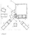
- the structure of the assembly web according to the invention will first be explained in more detail generally with reference to FIGS. 1 and 2.
- the mast 10 is composed of individual elements, each of which is assembled and connected to one another.
- the mast 10 is in engagement with a drive 11, on which the car 12 is held, via a toothed rack arrangement, not shown in detail.
- the drive 11 consists essentially of an electric motor and subsequent gear, which drives the pinions which engage in the rack arrangement.
- the basket 12 can thus be opened and closed.
- a ball slewing ring 13 is mounted on the roof of the car 12.
- the stationary part of the slewing ring 13 is firmly anchored to the frame of the car 12.
- the rotatable part of the slewing ring 13 is connected to a first mounting web part 14.
- This consists essentially of a rectangular tubular frame 15 which carries a walkable cover plate 16, preferably made of aluminum.
- a Railing 17 secures the working person.
- the assembly web consists only of the first web part 14, which can be rotated via the ball slewing ring 13. It can, as shown in FIG. 1, from the rest position, in which the web does not protrude beyond the side profile of the basket 12, which with A is rotated into different angular positions B to F.
- the ball slewing ring 13 can be locked in the individual twisting positions by spring pins 18.
- the slewing ring carries welded insertion tubes (not shown) for the spring pins.
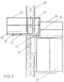
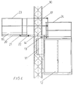
- FIGS. 1 to 4 a second mounting web part 19 which is displaceable for this purpose is provided on the first mounting web part 14.
- the displaceable web part 19 carries on both sides U-rails 20, which each overlap two pairs of rollers 21, 22 held on the first web part 14.
- the second mounting web part 19 is also provided with a safety railing 23.
- FIG. 3 shows the assembly web in the turned-out position of the assembly web part 14, but with a partially extended second assembly web part 19, while FIG. 4 shows the fully extended position of the second assembly web part 19.
- the car 12 is provided with a mounting hatch (not shown in detail) in its roof and a surrounding railing 24.
- FIG. 1 shows, continuously different end positions can be set in different angular positions, which are shown in the drawing with B to F.
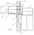
- FIGS. 5 to 7. A further embodiment of the assembly web is shown in FIGS. 5 to 7.
- the components described above are the same Provide reference numerals, so that a further description is unnecessary at this point.
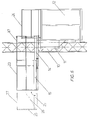
- This embodiment is characterized in that at the free end of the second mounting web part 19 there is a third mounting web part 25 which can be folded out about a horizontal axis.
- the protective railing 26 on the end rests on the bottom of the second mounting web part 19.
- An upper end railing 27 and a diagonal brace 28 are also folded out when swiveling out.
- the additional third mounting web part at the end not only leads to an extended throat of the mounting web, but also increases the usability, as is clear from FIG. 7.
- a stepless transition from the end working position is possible if the second web part 19 can be extended at least as far as the foldable third web part 25 increases the overall length of the assembly web.
- the power line is interrupted via a positively opened electrical contact (not shown in detail), i.e. the car cannot be opened or closed using the assembly control.
Landscapes
- Engineering & Computer Science (AREA)
- Structural Engineering (AREA)
- Civil Engineering (AREA)
- Transportation (AREA)
- Automation & Control Theory (AREA)
- Bridges Or Land Bridges (AREA)
Applications Claiming Priority (2)
| Application Number | Priority Date | Filing Date | Title |
|---|---|---|---|
| DE4336346 | 1993-10-25 | ||
| DE19934336346 DE4336346C2 (de) | 1993-10-25 | 1993-10-25 | Bauaufzug mit Montagesteg |
Publications (2)
| Publication Number | Publication Date |
|---|---|
| EP0649811A2 true EP0649811A2 (fr) | 1995-04-26 |
| EP0649811A3 EP0649811A3 (fr) | 1995-08-16 |
Family
ID=6500955
Family Applications (1)
| Application Number | Title | Priority Date | Filing Date |
|---|---|---|---|
| EP94116826A Withdrawn EP0649811A3 (fr) | 1993-10-25 | 1994-10-25 | Passerelle de montage pour ascenseurs de construction. |
Country Status (2)
| Country | Link |
|---|---|
| EP (1) | EP0649811A3 (fr) |
| DE (1) | DE4336346C2 (fr) |
Cited By (7)
| Publication number | Priority date | Publication date | Assignee | Title |
|---|---|---|---|---|
| EP0693453A3 (fr) * | 1994-07-22 | 1996-04-10 | Steinweg Hermann Gmbh Co Kg | Ascenseur de chantier |
| EP0739851A2 (fr) * | 1995-03-31 | 1996-10-30 | ALOYS ZEPPENFELD GMBH & CO. KG | Ascenseur de chantier |
| EP0839752A1 (fr) * | 1996-10-30 | 1998-05-06 | Allgemeine Baumaschinen Gesellschaft m.b.H. | Plate-forme pour ascenseur de chantier |
| WO2005087645A1 (fr) * | 2004-03-12 | 2005-09-22 | Alimak Ab | Systeme d'ascenseur |
| FR2936236A1 (fr) * | 2008-09-19 | 2010-03-26 | Jean Pierre Teso | Ascenseur d'acces aux postes de travail |
| EP3434637A1 (fr) * | 2017-07-26 | 2019-01-30 | HighStep Systems AG | Système de plateforme |
| IT202100000770A1 (it) * | 2021-01-18 | 2022-07-18 | Fiorenzo Sartor | Montacarichi da cantiere |
Citations (2)
| Publication number | Priority date | Publication date | Assignee | Title |
|---|---|---|---|---|
| FR2552413A1 (fr) * | 1983-09-22 | 1985-03-29 | Thyssen Industrie | Dispositif elevateur pour passerelle d'embarquement telescopique |
| DE3415265A1 (de) * | 1984-04-24 | 1985-10-31 | Hermann Steinweg GmbH & Co KG Baumaschinenfabrik, 4712 Werne | Aufzug, insbesondere bauaufzug |
Family Cites Families (3)
| Publication number | Priority date | Publication date | Assignee | Title |
|---|---|---|---|---|
| DE921172C (de) * | 1949-01-19 | 1954-12-09 | Richard Gladewitz | Fahrbares, ausziehbares Leitergeruest |
| DE1726933U (de) * | 1956-04-16 | 1956-07-26 | Victor Halstrick K G | Bauaufzug mit feststehender plattform und auf dieser drehbarem plattformteil. |
| DD289747A5 (de) * | 1989-12-05 | 1991-05-08 | Sekundant Pro Ingenium Patentanwalt R. Kaczor,De | Auslegerrollbuehne fuer bauaufzuege |
-
1993
- 1993-10-25 DE DE19934336346 patent/DE4336346C2/de not_active Expired - Fee Related
-
1994
- 1994-10-25 EP EP94116826A patent/EP0649811A3/fr not_active Withdrawn
Patent Citations (2)
| Publication number | Priority date | Publication date | Assignee | Title |
|---|---|---|---|---|
| FR2552413A1 (fr) * | 1983-09-22 | 1985-03-29 | Thyssen Industrie | Dispositif elevateur pour passerelle d'embarquement telescopique |
| DE3415265A1 (de) * | 1984-04-24 | 1985-10-31 | Hermann Steinweg GmbH & Co KG Baumaschinenfabrik, 4712 Werne | Aufzug, insbesondere bauaufzug |
Cited By (11)
| Publication number | Priority date | Publication date | Assignee | Title |
|---|---|---|---|---|
| EP0693453A3 (fr) * | 1994-07-22 | 1996-04-10 | Steinweg Hermann Gmbh Co Kg | Ascenseur de chantier |
| EP0739851A2 (fr) * | 1995-03-31 | 1996-10-30 | ALOYS ZEPPENFELD GMBH & CO. KG | Ascenseur de chantier |
| EP0739851A3 (fr) * | 1995-03-31 | 1996-12-04 | Zeppenfeld Aloys Gmbh | |
| EP0839752A1 (fr) * | 1996-10-30 | 1998-05-06 | Allgemeine Baumaschinen Gesellschaft m.b.H. | Plate-forme pour ascenseur de chantier |
| WO2005087645A1 (fr) * | 2004-03-12 | 2005-09-22 | Alimak Ab | Systeme d'ascenseur |
| US7665582B2 (en) | 2004-03-12 | 2010-02-23 | Alimak Ab | Elevator car with a working platform |
| CN1930075B (zh) * | 2004-03-12 | 2010-09-29 | 阿力马克公司 | 电梯系统 |
| FR2936236A1 (fr) * | 2008-09-19 | 2010-03-26 | Jean Pierre Teso | Ascenseur d'acces aux postes de travail |
| EP3434637A1 (fr) * | 2017-07-26 | 2019-01-30 | HighStep Systems AG | Système de plateforme |
| IT202100000770A1 (it) * | 2021-01-18 | 2022-07-18 | Fiorenzo Sartor | Montacarichi da cantiere |
| EP4029820A1 (fr) * | 2021-01-18 | 2022-07-20 | Fiorenzo Sartor | Ascenseur de chantier |
Also Published As
| Publication number | Publication date |
|---|---|
| EP0649811A3 (fr) | 1995-08-16 |
| DE4336346A1 (de) | 1995-04-27 |
| DE4336346C2 (de) | 1998-05-14 |
Similar Documents
| Publication | Publication Date | Title |
|---|---|---|
| DE69434331T2 (de) | Baustellen plattform | |
| EP2088113A2 (fr) | Dispositif de levage combiné pour personnes et charges | |
| DE3143802A1 (de) | Kranwagen mit teleskop-ausfahrstuetzen und kraftbetaetigten schraubenspindeleinrichtungen hierfuer | |
| EP0611726B1 (fr) | Elévateur pour le montage et le démontage de composants de voitures | |
| DE2307355A1 (de) | Liftvorrichtung fuer den fuehrerstand eines krans in fachwerkausfuehrung | |
| EP0649811A2 (fr) | Passerelle de montage pour ascenseurs de construction | |
| DE1281128B (de) | Fahrbarer Mehrzweckkran | |
| DE3323513A1 (de) | Winde fuer luftfahrzeug | |
| DE7209702U (de) | Arbeitsgeruest mit senkrecht bewegbarer galerie oder plattform | |
| EP2935751B1 (fr) | Système d'échelle, en particulier échelle de pompier et véhicule qui en est équipé | |
| DE4344210A1 (de) | Umlaufend hängende Arbeitsbühne für turmartige Bauwerke | |
| DE19858550C2 (de) | Wiederverwendungsfähige Treppe | |
| DE8524989U1 (de) | Aus mehreren Führungsschienen gebildeter Schrägaufzug | |
| DE1216914B (de) | Brueckenbesichtigungsgeraet | |
| EP1373120B1 (fr) | Fleche telescopique pour une grue automotrice | |
| DE19631547A1 (de) | Teleskopausleger, insbesondere für stationäre oder fahrbare Krane | |
| DE19641191A1 (de) | Teleskopausleger, insbesondere für stationäre und fahrbare Krane | |
| DE10206242B4 (de) | Windkraftanlage und zugehöriger Mast | |
| CH667447A5 (de) | Oben drehender turmdrehkran. | |
| DE10114359A1 (de) | Mobile Fördereinrichtung mit Verteilermast und begehbaren Pritschen | |
| EP0846644A1 (fr) | Ascenseur | |
| DE1198981B (de) | Montagegeraet fuer Rohrantennenelemente und Mastbauwerke | |
| DE4221516A1 (de) | Bettkonstruktion | |
| DE1481911A1 (de) | Fahrbares Hubgeruest | |
| CH687935A5 (de) | Arbeitsgrube, insbesondere fuer Kraftfahrzeugwerkssaetten, mit laengslaufenden grubenrandbegrenzenden Stahlprofilen. |
Legal Events
| Date | Code | Title | Description |
|---|---|---|---|
| PUAI | Public reference made under article 153(3) epc to a published international application that has entered the european phase |
Free format text: ORIGINAL CODE: 0009012 |
|
| AK | Designated contracting states |
Kind code of ref document: A2 Designated state(s): AT DE GB IT NL SE |
|
| PUAL | Search report despatched |
Free format text: ORIGINAL CODE: 0009013 |
|
| AK | Designated contracting states |
Kind code of ref document: A3 Designated state(s): AT DE GB IT NL SE |
|
| STAA | Information on the status of an ep patent application or granted ep patent |
Free format text: STATUS: THE APPLICATION IS DEEMED TO BE WITHDRAWN |
|
| 18D | Application deemed to be withdrawn |
Effective date: 19960217 |