EP0641986A1 - Wärmetauscher und Verfahren zu seiner Herstellung - Google Patents
Wärmetauscher und Verfahren zu seiner Herstellung Download PDFInfo
- Publication number
- EP0641986A1 EP0641986A1 EP94113689A EP94113689A EP0641986A1 EP 0641986 A1 EP0641986 A1 EP 0641986A1 EP 94113689 A EP94113689 A EP 94113689A EP 94113689 A EP94113689 A EP 94113689A EP 0641986 A1 EP0641986 A1 EP 0641986A1
- Authority
- EP
- European Patent Office
- Prior art keywords
- tubes
- end parts
- disposed
- plates
- pair
- Prior art date
- Legal status (The legal status is an assumption and is not a legal conclusion. Google has not performed a legal analysis and makes no representation as to the accuracy of the status listed.)
- Granted
Links
- 238000000034 method Methods 0.000 title claims description 38
- 238000004519 manufacturing process Methods 0.000 title claims description 25
- 238000005219 brazing Methods 0.000 claims abstract description 25
- 239000000498 cooling water Substances 0.000 claims description 14
- 239000000463 material Substances 0.000 description 8
- 229910052782 aluminium Inorganic materials 0.000 description 5
- XAGFODPZIPBFFR-UHFFFAOYSA-N aluminium Chemical compound [Al] XAGFODPZIPBFFR-UHFFFAOYSA-N 0.000 description 5
- 230000007547 defect Effects 0.000 description 5
- OKTJSMMVPCPJKN-UHFFFAOYSA-N Carbon Chemical compound [C] OKTJSMMVPCPJKN-UHFFFAOYSA-N 0.000 description 3
- 229910052799 carbon Inorganic materials 0.000 description 3
- 239000000155 melt Substances 0.000 description 3
- 230000007423 decrease Effects 0.000 description 2
- 230000003247 decreasing effect Effects 0.000 description 2
- 230000002950 deficient Effects 0.000 description 2
- 239000011347 resin Substances 0.000 description 2
- 229920005989 resin Polymers 0.000 description 2
- 230000015556 catabolic process Effects 0.000 description 1
- 238000006243 chemical reaction Methods 0.000 description 1
- 210000000078 claw Anatomy 0.000 description 1
- 238000001816 cooling Methods 0.000 description 1
- 238000006731 degradation reaction Methods 0.000 description 1
- 230000000694 effects Effects 0.000 description 1
- 239000012530 fluid Substances 0.000 description 1
- 229910052751 metal Inorganic materials 0.000 description 1
- 239000002184 metal Substances 0.000 description 1
- 238000012856 packing Methods 0.000 description 1
- 238000005096 rolling process Methods 0.000 description 1
- 125000006850 spacer group Chemical group 0.000 description 1
- 238000003466 welding Methods 0.000 description 1
Images


Classifications
-
- F—MECHANICAL ENGINEERING; LIGHTING; HEATING; WEAPONS; BLASTING
- F28—HEAT EXCHANGE IN GENERAL
- F28F—DETAILS OF HEAT-EXCHANGE AND HEAT-TRANSFER APPARATUS, OF GENERAL APPLICATION
- F28F9/00—Casings; Header boxes; Auxiliary supports for elements; Auxiliary members within casings
- F28F9/02—Header boxes; End plates
- F28F9/04—Arrangements for sealing elements into header boxes or end plates
- F28F9/16—Arrangements for sealing elements into header boxes or end plates by permanent joints, e.g. by rolling
- F28F9/18—Arrangements for sealing elements into header boxes or end plates by permanent joints, e.g. by rolling by welding
- F28F9/182—Arrangements for sealing elements into header boxes or end plates by permanent joints, e.g. by rolling by welding the heat-exchange conduits having ends with a particular shape, e.g. deformed; the heat-exchange conduits or end plates having supplementary joining means, e.g. abutments
-
- B—PERFORMING OPERATIONS; TRANSPORTING
- B21—MECHANICAL METAL-WORKING WITHOUT ESSENTIALLY REMOVING MATERIAL; PUNCHING METAL
- B21D—WORKING OR PROCESSING OF SHEET METAL OR METAL TUBES, RODS OR PROFILES WITHOUT ESSENTIALLY REMOVING MATERIAL; PUNCHING METAL
- B21D53/00—Making other particular articles
- B21D53/02—Making other particular articles heat exchangers or parts thereof, e.g. radiators, condensers fins, headers
- B21D53/08—Making other particular articles heat exchangers or parts thereof, e.g. radiators, condensers fins, headers of both metal tubes and sheet metal
- B21D53/085—Making other particular articles heat exchangers or parts thereof, e.g. radiators, condensers fins, headers of both metal tubes and sheet metal with fins places on zig-zag tubes or parallel tubes
-
- F—MECHANICAL ENGINEERING; LIGHTING; HEATING; WEAPONS; BLASTING
- F28—HEAT EXCHANGE IN GENERAL
- F28F—DETAILS OF HEAT-EXCHANGE AND HEAT-TRANSFER APPARATUS, OF GENERAL APPLICATION
- F28F9/00—Casings; Header boxes; Auxiliary supports for elements; Auxiliary members within casings
- F28F9/001—Casings in the form of plate-like arrangements; Frames enclosing a heat exchange core
-
- F—MECHANICAL ENGINEERING; LIGHTING; HEATING; WEAPONS; BLASTING
- F28—HEAT EXCHANGE IN GENERAL
- F28F—DETAILS OF HEAT-EXCHANGE AND HEAT-TRANSFER APPARATUS, OF GENERAL APPLICATION
- F28F9/00—Casings; Header boxes; Auxiliary supports for elements; Auxiliary members within casings
- F28F9/02—Header boxes; End plates
- F28F9/04—Arrangements for sealing elements into header boxes or end plates
- F28F9/16—Arrangements for sealing elements into header boxes or end plates by permanent joints, e.g. by rolling
-
- F—MECHANICAL ENGINEERING; LIGHTING; HEATING; WEAPONS; BLASTING
- F28—HEAT EXCHANGE IN GENERAL
- F28F—DETAILS OF HEAT-EXCHANGE AND HEAT-TRANSFER APPARATUS, OF GENERAL APPLICATION
- F28F21/00—Constructions of heat-exchange apparatus characterised by the selection of particular materials
- F28F21/06—Constructions of heat-exchange apparatus characterised by the selection of particular materials of plastics material
- F28F21/067—Details
-
- Y—GENERAL TAGGING OF NEW TECHNOLOGICAL DEVELOPMENTS; GENERAL TAGGING OF CROSS-SECTIONAL TECHNOLOGIES SPANNING OVER SEVERAL SECTIONS OF THE IPC; TECHNICAL SUBJECTS COVERED BY FORMER USPC CROSS-REFERENCE ART COLLECTIONS [XRACs] AND DIGESTS
- Y10—TECHNICAL SUBJECTS COVERED BY FORMER USPC
- Y10T—TECHNICAL SUBJECTS COVERED BY FORMER US CLASSIFICATION
- Y10T29/00—Metal working
- Y10T29/49—Method of mechanical manufacture
- Y10T29/4935—Heat exchanger or boiler making
- Y10T29/49373—Tube joint and tube plate structure
- Y10T29/49375—Tube joint and tube plate structure including conduit expansion or inflation
Definitions
- the present invention generally relates to a method for producing a heat exchanger and to the heat exchanger produced by the method. More particularly, the present invention relates to a stack type heat exchanger that is brazed when a header plate disposed at an upper side is supported by jigs and cores and to the method for producing the stack type heat exchanger.
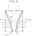
- FIGS. 5 and 6 it is known to stack cores 103 with a plurality of tubes 101 in order to form engine cooling water passages. Furthermore, it is known to assemble a plurality of corrugated fins 102 and connect a pair of header plates 104 to both ends of tubes 101, and also to connect header plates 104 using side plates 105. Cores 103 are hung from an upper header plate 104 in a downward direction. Upper header plate 104 is supported by carbon jigs 106. An assembly including these structure is integrally brazed within a furnace. Each tube 101 is lightly press fitted into each press-fitting hole 107 within the pair of header plates 104. Cores 103 are held between side plates 105 at both sides of the heat exchanger (in some cases, cores 103 are held between side plates 105 and bundled with wires, etc.).
- each tube 101 melts and flows, the diameter of each tube 101 is reduced, and at the same time, due to the exposure to high temperatures, the press-fitting force of each tube 101 press fits into each press-fitting hole 107 in the header plate 104 is decreased, whereby cores 103 hung from the upper header plate 104 may slide down by due to their own weight. If core 103 slides down from upper header plate 104, side plates 105 also slide down with cores 103. As illustrated in FIG. 7, a gap t2 forms between outermost part 105b of side plate 105 and the back of opposite surface 104a of header plate 104.
- side plates 105 and header plates 104 may be brazed to each other. If both gaps t1 and t2 occur, defects will be caused such that side plates 105 and header plates 104 are not brazed to each other, thus impairing the strength of the resulting heat exchanger.
- tube flaring pins are inserted into the open ends of each tube 101 press fitted into each press-fitting hole 107 in header plates 104, and the end parts of each tube 101 are flared to an angle within a range from 20° to 30° to improve the connection force between each press-fitting hole 107 and the end parts of each tube 101.
- each tube 101 is softened during the brazing process due to the high brazing temperature. As a result, the flared angle of the flared part of the tube 101 is narrowed by the vertical force applied to the flared part of tube 101 (arrow B).
- the core 103 hung from the upper header plate 104 will slide down due to its weight, whereby, as illustrated in FIG. 7, the gap t2 is formed between the outermost part 105b of the side plate 105 and the opposite surface 104a of the header plate 104.
- each tube 101 press fitted into the press-fitting holes 107 in the header plates 104 are flared to an angle of approximately 180°. If the flared angle is set to approximately 180° in this way, any horizontal force will not cause part of the tube 101 to widen, even if the core 103 is hung from the upper header plate 104 through each tube 101. Accordingly, the widened angle of widening part of each tube 101 will not be narrowed during the brazing process, whereby the core 103 hung from the upper header plate 104 will not slide down due to its own weight. As a result, the gap t2 is not formed between the outermost part 105b of the side plate 105 and the opposite surface 104a of the header plate 104.
- the loads applied to the end parts of the header plate 104 are supported by the side plates 105, which have a sufficiently high strength to support the load, and the tubes 101, which do not have a sufficiently high strength. However, loads applied to the central area of the assembly of cores 103 are supported only by the tubes 101, which is not desirable.
- the present invention includes a method for producing a heat exchanger having cores stacked with a plurality of tubes having first and second end parts provided with engine cooling water passages therein and a plurality of corrugated fins, a pair of header plates including a plurality of press-fitting holes, and a pair of side plates disposed at sides of the cores for connecting the pair of header plates to each other in a state where the cores are held therebetween.
- the method includes press fitting the first and second end parts of the plurality of tubes into the press-fitting holes in the pair of header plates.
- the method further includes contacting end parts of the pair of side plates with the pair of head plates, thus forming a heat exchanger assembly.
- the method includes flaring at least one of the first and second end parts of the tubes to be disposed on an upper side during blazing, wherein tubes disposed in a central parts of the header plate are flared to have a smaller degree than those tubes disposed proximate the side plates, thus preventing the tubes from sliding during blazing.
- the method includes brazing the assembly within a furnace.
- This method produces a heat exchanger comprising a plurality of cores stacked with a plurality of tubes, each tube having first and second end parts, provided with engine cooling water passages therein and a plurality of corrugated fins zigzaggedly formed, a pair of header plates including a plurality of press-fitting holes into which the end parts of the plurality of tubes are press fitted and connected, and a pair of side plates disposed at sides of the plurality of cores for connecting the pair of header plates to each other in the state that the cores are held therebetween, wherein at least one end of the plurality of tubes to be press fitted into the press-fitting holes in the header plates is flared, and the flared angles of the end parts of the tubes disposed proximate the side plates is set to be larger than the flared angle of the end parts of the tubes disposed in a central part of the assembly of the cores.
- a pair of header plates and a pair of side plates can be securely brazed without complicating the shapes of the components of the heat exchanger, such as header plates and side plates, by setting the flare angle of the end parts of the tubes disposed in the side plate areas to be larger than the flare angle of the end parts of the tubes disposed in the central part of the core assembly.
- the flare angle of the end parts of the tubes disposed in the central part of the core assembly is set to be smaller than the flare angle of the end parts of the tubes disposed in the side plate areas, loads applied to the tubes disposed in the central part of the core assembly can be minimized. As a result, the buckling of the tubes disposed in the central part of the core assembly or the deformation of the header plate can be prevented, whereby the pair of header plates and the pair of side plates can be securely brazed.
- the press fitting force of each tube press fitted into each press-fitting hole and the hardness of the tubes during the brazing process is further reduced. Accordingly, the a defect that the core, etc. hung from the upper header plate slides down due to its own weight during the brazing process can easily occur.
- the method according to the present invention even if the tubes are made thinner, the sliding downward of the tubes disposed in the side plate areas during the brazing process is prevented, whereby the pair of header plates and the pair of side plates can be securely brazed.
- FIGS. 1, 2 and 3 illustrate the first embodiment of the present invention.
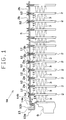
- FIG. 1 is a cross-sectional view illustrating the main part of a radiator
- FIG. 2 is a front view illustrating the radiator
- FIG. 3 is a front view of a core assembly.
- Radiator 1 for cooling engine cooling water, is referred to as an example of a heat exchanger.
- the radiator 1 comprises a core assembly 4 including a plurality of tubes 2 and a plurality of corrugated fins 3 both of which are alternately stacked, a pair of header plates 5 connected to the plurality of tubes 2 at respective ends thereof, an inlet tank 7 and an outlet tank 8 both of which include header tanks 6 fixed to the header plates 5 respectively, and a pair of side plates 9 disposed on both sides of the core assembly 4 for connecting the pair of header plates 5 to each other at the ends thereof.
- the components of the radiator 1 except for the header tanks 6, i.e., the core assembly 4 (including the tubes 2 and the corrugated fins 3), the header plates 5 and the side plates 9, are made of aluminum, which are integrally brazed in a furnace into the main body of the radiator 1.
- the header tanks 6 are made of resin, and are fixed to the header plates 5 of the brazed main body of the radiator 1 through packings (not illustrated).
- the tube 2 is made of a thin aluminum plate which is rolled and then seamed by means of welding into a tube having a crushed and elliptical cross section.
- the inside of the tube 2 forms a fluid passage 11 that allows the engine cooling water to flow therethrough.
- the surface of the tube 2 is clad with a brazing material.
- the corrugated fin 3 is made of a thin aluminum plate strip zigzaggedly formed by means of rolling.
- the air-flow part of the corrugated fin 3 is equipped with louvres (not illustrated) for higher heat exchange efficiency.
- the header plate 5 is made of an aluminum plate which is pressed into the required shape and then clad with a brazing material on one side thereof, the side which interfaces with the external surface of the header tank 6.
- the header plate 5 includes a plurality of press-fitting holes 12 into which the plurality of tubes 2 are press fitted.
- the header plate 5 has U-shaped grooves 13 at both distal end parts into which the end parts of the header tank 6 are inserted.
- the press-fitting holes 12 of this embodiment are formed to be open into the header tank 6 by a burring process.
- the outer wall 13a of the groove 13 is provided with a number of claws (not illustrated), which are intended to be folded after an open end of the header tank 6 is inserted into the groove 13 so that the header tank 6 can be fixed to the header plate 5.
- the side plate 9 is made of an aluminum plate which is pressed to have a U-shape cross section and then clad with a brazing material, at least on the side to which the corrugated fin 3 is to be connected.
- the end parts of the side plate 9 are provided with connecting parts 14, respectively which are pressed into a rough U-shape.
- the back part 14a of the connecting part 14 is to be connected to the back part of the inner wall 13b of the groove 13 of the header plate 5, and the outermost wall 14b of the connecting part 14 is to be connected to the opposite surface 5a of the header plate 5 facing the inner surface of the other header plate 5.
- the tubes 2 disposed near either side of the side plates 9 accounting for approximately 10% of the total tubes are flared to an angle of approximately 180°, the percentage of the tubes 2 that are flared to an angle of approximately 180° may be changed to an adequate percentage according to the weight of the core assembly 4, etc.
- the plurality of tubes 2 and the plurality of corrugated fins 3 are alternately stacked, and then side plates 9 are disposed at both sides thereof.
- the pair of header plates 5 are disposed at the end parts of the plurality of tubes 2, then the end parts of all the tubes 2 are press fitted into the respective press-fitting holes 12 in the header plates 5. Then the connecting parts 14 at the end parts of the pair of side plates 9 are contacted to the pair of header plates 5 (first process).
- the main body part 1a (FIG. 1) assembled in the first process (an assembly of the plurality of tubes 2, the plurality of corrugated fins 3, the pair of header plates 5 and the pair of side plates 9 illustrated in FIG. 3) is set into a tube widening device (not illustrated).
- the tube widening device press fits large flaring pins having an angle of approximately 180° into the engine cooling water passages 11 of the tubes 2 disposed near either of the side plates 9 and accounting for approximately 10% of all the tubes 2. Smaller flaring pins, having an angle within a range from approximately 60° to about 80° into the engine cooling water passages 11 of the remaining about 80% of the tubes 2 disposed in the central area of the core assembly 4 indicated by ⁇ in FIG. 3.
- the large widening parts 2a with a flare angle of approximately 180° are formed on the end parts of approximately 10% of the tubes 2 disposed near either end of the core assembly 4, and the small widening parts 2b with a flare angle within a range from approximately 60° to approximately 80° are formed on the end parts of approximately 80% of the tubes 2 disposed in the central area of the core assembly 4 (second process).
- the tube end widening device has disposed on its upper and lower sides the large flaring pins to be press fitted into the engine cooling water passages 11 at the end parts of approximately 10% of the tubes 2 disposed near either of the side plates 9 to widen the end parts of the above tubes 2 to an angle of 180° and the smaller flaring pins to be press fitted into the engine cooling water passages 11 at the end parts of approximately 80% of the tubes 2 disposed in the central part of the core assembly 4 to widen the end parts of the above tubes 2 to an angle within a range from 60° to 80.°°.
- the large flaring pins and the small flaring pins which are designed to widen the end parts of the tubes 2 to make the flared outer peripheries of the tubes 2 match the respective press fitting holes 12, comprise tip guiding parts to be inserted into the engine cooling water passages 11 to prevent the engine cooling water passages 11 from being narrowed during the widening process and widening parts for widening the end parts of the tubes 2 towards both sides. Between the large flaring pins and the small flaring pins are disposed spacers so that the intervals therebetween match the interval between the tubes 2.
- the tube end widening device is equipped with an upper supporter at the upper side for supporting the large flaring pins and the small flaring pins and a lower supporter at the lower side for supporting the larger flaring pins and the small flaring pins.
- At least one of the upper supporter and lower supporter is so provided as to be driven up/down by a driving means.
- the main body part 1a assembled in the first process. Then, either of the upper supporter or the lower supporter is driven by a predetermined amount for a driving stroke, and then subjected to a predetermined amount of load.
- the large widening parts 2a are formed at the end parts of approximately 10% of the tubes 2 disposed near either side of the core assembly 4 and the small widening parts 2b are formed at the end parts of approximately 80% of the tubes 2 disposed in the central part of the core assembly 4.
- the tube end widening device is equipped with a clamp for supporting the core assembly 4 from both sides of the pair of side plates 9 during the widening process.
- This clamp is applied to both sides of the core assembly 4 to protect the tubes 2 disposed near either side of the core assembly 4 and the pair of side plates 9 from deformation.
- the large widening parts 2a and the small widening parts 2b are formed at the end parts of all the tubes 2 in the second process.
- This arrangement prevents the header plates 5 at both sides from moving outwards.
- between the header plates 5 at both sides are disposed the pair of side plates 9 in contact with the above header plates 5.
- This arrangement can prevent the header plates 5 at both sides from moving inward. That is, even if some loads are applied to the main body part 1a from the outside, the assembled state achieved in the first process can be maintained.
- the header plate 5 to be supported by the jigs may be either of the header plate 5 forming the inlet tank 7 or the header plate 5 forming the outlet tank 8.
- brazing material clad on each component thereof melts. Then, the melted brazing material spreads to the contacting part of each component, forming a brazing core.
- the power of the press-fitting holes 12 to hold the tubes 2 decreases to such an extent that only the holding power of the press-fitting holes 12 can not resist the downward force due to the self-weight of the core assembly 4.
- the upper end of approximately 10% of the tubes 2 disposed near either side of the core assembly 4 are flared to an angle approximately 180°, even if the hardness of the tubes 2 is lowered, the flared angle will not be narrowed by the self-weight of the core assembly 4. This arrangement can protect the tubes 2 disposed near either side of the core assembly 4 from slipping down from the upper header plate 5.
- the pair of header plates 5 and the pair of side plates 9 can exactly be brazed and thereby the degradation in the strength of the radiator 1 can exactly be prevented by widening the end parts of approximately 10% of the tubes 2 disposed near either side of the core assembly 4 to an angle of approximately 180°, which is larger than the flared angle within a range from approximately 60° to 80° applied to the end parts of approximately 80% of the tubes 2 disposed in the central part of the core assembly 4.
- either one of the pair of header plates 5 can be supported by the carbon jig. This arrangement facilitates the handling of the main body part 1a during the manufacturing processes.
- the state of assembling achieved in the first process can be maintained, even if some loads are applied from the outside to the main body part 1a.
- This arrangement also facilitates the handling of the main body part 1a during the manufacturing processes.
- the header plate 5 disposed at the lower side will not come off from the tubes 2. This arrangement can prevent the occurrence of the defective brazing at the lower side.
- FIG. 4 depicts a cross-sectional view illustrating the main part of the radiator 1 according to the second embodiment of the present invention.
- the flared angle of approximately 10% of the tubes 2 disposed near either side of the core assembly 4 is set to an angle approximately 180° and the flared angle of remaining approximately 80% of the tubes 2 disposed in the central part of the core assembly 4 is set to an angle within a range from approximately 60° to approximately 80°.
- the flared angles of the end parts of the tubes 2 gradually decrease in the size of the angle as the tubes progress from the sides near the side plate 9 towards the center of the core assembly 4.
- the widening parts 2c of the tubes 2 near either side of the side plate 9 are flared to the largest angle of approximately 180°, while the widening parts 2d of the tubes 2 in the central part of the core assembly 4 are flared to the smallest angle of approximately 0°.
- the tubes 2 with large flared angles and the tubes 2 with small flared angles are alternately disposed every one or more than one tubes 2 or randomly disposed.
- more than three different flared angles are set and the tubes 2 with these three different flared angles respectively are alternately disposed every one or more than one tubes 2 or continuously or even randomly disposed.
- press-fitting holes 12 of the header plates 5 are formed to be open into the header tank 6 by a burring process, it is acceptable that the press-fitting holes 12 are formed into mere through holes.
- radiator 1 is used as an example of a heat exchanger
- header tanks 6 are made of a resin
- tank headers 6 are made of a metal and integrally brazed with other components including the cores 3.
Landscapes
- Engineering & Computer Science (AREA)
- Mechanical Engineering (AREA)
- Physics & Mathematics (AREA)
- Thermal Sciences (AREA)
- General Engineering & Computer Science (AREA)
- Heat-Exchange Devices With Radiators And Conduit Assemblies (AREA)
- Details Of Heat-Exchange And Heat-Transfer (AREA)
Applications Claiming Priority (4)
| Application Number | Priority Date | Filing Date | Title |
|---|---|---|---|
| JP21778593 | 1993-09-01 | ||
| JP217785/93 | 1993-09-01 | ||
| JP158958/94 | 1994-07-11 | ||
| JP06158958A JP3125834B2 (ja) | 1993-09-01 | 1994-07-11 | 熱交換器およびその製造方法 |
Publications (2)
| Publication Number | Publication Date |
|---|---|
| EP0641986A1 true EP0641986A1 (de) | 1995-03-08 |
| EP0641986B1 EP0641986B1 (de) | 1997-04-23 |
Family
ID=26485919
Family Applications (1)
| Application Number | Title | Priority Date | Filing Date |
|---|---|---|---|
| EP94113689A Expired - Lifetime EP0641986B1 (de) | 1993-09-01 | 1994-09-01 | Wärmetauscher und Verfahren zu seiner Herstellung |
Country Status (6)
| Country | Link |
|---|---|
| US (1) | US5457885A (de) |
| EP (1) | EP0641986B1 (de) |
| JP (1) | JP3125834B2 (de) |
| CN (1) | CN1074531C (de) |
| AU (1) | AU684091B2 (de) |
| DE (1) | DE69402786T2 (de) |
Cited By (4)
| Publication number | Priority date | Publication date | Assignee | Title |
|---|---|---|---|---|
| EP0802386A1 (de) * | 1996-04-17 | 1997-10-22 | Sanden Corporation | Rohrbündel-Wärmetauscher |
| DE19757034A1 (de) * | 1997-12-20 | 1999-06-24 | Behr Gmbh & Co | Wärmetauscher, insbesondere Ladeluftkühler |
| DE102006002932A1 (de) * | 2006-01-21 | 2007-07-26 | Modine Manufacturing Co., Racine | Wärmetauscher und Herstellungsverfahren für Wärmetauscher |
| US8177932B2 (en) | 2009-02-27 | 2012-05-15 | International Mezzo Technologies, Inc. | Method for manufacturing a micro tube heat exchanger |
Families Citing this family (34)
| Publication number | Priority date | Publication date | Assignee | Title |
|---|---|---|---|---|
| US6178292B1 (en) | 1997-02-06 | 2001-01-23 | Denso Corporation | Core unit of heat exchanger having electric heater |
| US6249968B1 (en) * | 1999-08-25 | 2001-06-26 | Visteon Global Technologies, Inc. | Method of making a robust gosper fin heat exchanger |
| IT1319494B1 (it) * | 2000-11-30 | 2003-10-20 | Nuovo Pignone Spa | Piastra tubiera per fasci tubieri per reattori chimici e scambiatoridi calore in genere |
| DE10103570A1 (de) * | 2001-01-26 | 2002-08-01 | Modine Mfg Co | Wärmetauscher und Herstellungsverfahren |
| DE10114078A1 (de) * | 2001-03-22 | 2002-09-26 | Modine Mfg Co | Wärmetauscher und Herstellungsverfahren |
| DE10147192A1 (de) | 2001-09-25 | 2003-04-17 | Modine Mfg Co | Wärmeaustauscher mit einem Rippen-Flachrohr-Block und Herstellungsverfahren |
| US6786275B2 (en) * | 2002-05-23 | 2004-09-07 | Valeo Engine Cooling | Heat exchanger header assembly |
| JP2005121350A (ja) * | 2003-05-29 | 2005-05-12 | Denso Corp | 熱交換器およびその製造方法 |
| DE102004029090A1 (de) * | 2003-06-20 | 2005-01-27 | Denso Corp., Kariya | Herstellungsverfahren eines Wärmetauschers und Aufbau desselben |
| US8438728B2 (en) * | 2006-01-19 | 2013-05-14 | Modine Manufacturing Company | Flat tube, flat tube heat exchanger, and method of manufacturing same |
| US8281489B2 (en) * | 2006-01-19 | 2012-10-09 | Modine Manufacturing Company | Flat tube, flat tube heat exchanger, and method of manufacturing same |
| JP2009524002A (ja) * | 2006-01-19 | 2009-06-25 | モーディーン・マニュファクチャリング・カンパニー | フラットチューブ、フラットチューブ型熱交換器及びその製造方法 |
| US20090019696A1 (en) * | 2006-01-19 | 2009-01-22 | Werner Zobel | Flat tube, flat tube heat exchanger, and method of manufacturing same |
| US8091621B2 (en) * | 2006-01-19 | 2012-01-10 | Modine Manufacturing Company | Flat tube, flat tube heat exchanger, and method of manufacturing same |
| US20090014165A1 (en) * | 2006-01-19 | 2009-01-15 | Werner Zobel | Flat tube, flat tube heat exchanger, and method of manufacturing same |
| US8434227B2 (en) | 2006-01-19 | 2013-05-07 | Modine Manufacturing Company | Method of forming heat exchanger tubes |
| US7921559B2 (en) * | 2006-01-19 | 2011-04-12 | Modine Manufacturing Company | Flat tube, flat tube heat exchanger, and method of manufacturing same |
| US8683690B2 (en) * | 2006-01-19 | 2014-04-01 | Modine Manufacturing Company | Flat tube, flat tube heat exchanger, and method of manufacturing same |
| US8191258B2 (en) * | 2006-01-19 | 2012-06-05 | Modine Manufacturing Company | Flat tube, flat tube heat exchanger, and method of manufacturing same |
| DE102007004993A1 (de) | 2007-02-01 | 2008-08-07 | Modine Manufacturing Co., Racine | Herstellungsverfahren für Flachrohre und Walzenstraße |
| WO2010048553A2 (en) * | 2008-10-23 | 2010-04-29 | Kesseli James B | Window system for a solar receiver and method and solar receiver system employing same |
| US20100175862A1 (en) * | 2009-01-14 | 2010-07-15 | Franklin David A | Brazed aluminum heat exchanger with split core arrangement |
| DE102010023384B4 (de) | 2010-06-10 | 2014-08-28 | Modine Manufacturing Co. | Herstellungsverfahren, insbesondere für Rohre und Abreißvorrichtung |
| WO2012088057A1 (en) * | 2010-12-21 | 2012-06-28 | Carrier Corporation | Automated brazing system with first and second set of burners |
| CN102705967A (zh) * | 2011-03-28 | 2012-10-03 | 乐金电子(天津)电器有限公司 | 一种换热器底板 |
| DE102012017130B4 (de) * | 2012-09-01 | 2016-06-16 | Man Diesel & Turbo Se | Laser-Rohreinschweißen |
| JP6455940B2 (ja) * | 2013-04-24 | 2019-01-23 | デーナ、カナダ、コーパレイシャン | 給気冷却器用のフィン支持構造 |
| DE102013212939A1 (de) | 2013-07-03 | 2015-01-08 | Behr Gmbh & Co. Kg | Herstellungsverfahren für einen Wärmetauscher und Werkzeug zur Herstellung des Wärmetauschers |
| JP5953323B2 (ja) * | 2014-02-14 | 2016-07-20 | 株式会社ティラド | 熱交換器 |
| CN110712004A (zh) * | 2019-09-24 | 2020-01-21 | 福建聚光精密件制造有限公司 | 一种喇叭口铜管的加工设备及其加工方法 |
| US11512800B2 (en) * | 2020-08-24 | 2022-11-29 | Rheem Manufacturing Company | Method of forming assembly between panel and tube |
| CN111843085B (zh) * | 2020-09-07 | 2024-03-12 | 贵州永红散热器有限责任公司 | 一种提高管嘴与筋板翻边孔焊合率的方法及工装 |
| US11924996B2 (en) * | 2020-09-30 | 2024-03-05 | Coolit Systems, Inc. | Liquid-cooling devices, and systems, to cool multi-chip modules |
| CN113188362B (zh) * | 2021-05-11 | 2022-04-12 | 浙江银轮新能源热管理系统有限公司 | 壳体及换热器 |
Citations (2)
| Publication number | Priority date | Publication date | Assignee | Title |
|---|---|---|---|---|
| DE2320866A1 (de) * | 1972-04-26 | 1973-11-08 | Chausson Usines Sa | Verstaerkungsanordnung fuer waermetauscher |
| US4813112A (en) * | 1982-04-16 | 1989-03-21 | Societe Anonyme Des Usines Chausson | Method for reinforcing by means of small plates at least end rows of tubes engaged into tube end plates for constituting a heat exchanger |
Family Cites Families (5)
| Publication number | Priority date | Publication date | Assignee | Title |
|---|---|---|---|---|
| US3972371A (en) * | 1972-04-26 | 1976-08-03 | Societe Anonyme Des Usines Chausson | Tube and tube-plate assembly |
| JPS59180295A (ja) * | 1983-03-30 | 1984-10-13 | Nippon Denso Co Ltd | 熱交換器及びその製造方法 |
| US4730669A (en) * | 1986-02-03 | 1988-03-15 | Long Manufacturing Ltd. | Heat exchanger core construction utilizing a diamond-shaped tube-to-header joint configuration |
| US4700469A (en) * | 1986-03-24 | 1987-10-20 | General Motors Corporation | Detachable clamp for fixturing heat exchanger core assemblies for brazing in combination with the heat exchanger core |
| FR2674321B1 (fr) * | 1991-03-20 | 1993-06-04 | Valeo Thermique Moteur Sa | Echangeur de chaleur a plusieurs rangees de tubes, en particulier pour vehicule automobile. |
-
1994
- 1994-07-11 JP JP06158958A patent/JP3125834B2/ja not_active Expired - Fee Related
- 1994-08-31 US US08/299,019 patent/US5457885A/en not_active Expired - Lifetime
- 1994-09-01 EP EP94113689A patent/EP0641986B1/de not_active Expired - Lifetime
- 1994-09-01 AU AU71628/94A patent/AU684091B2/en not_active Ceased
- 1994-09-01 DE DE69402786T patent/DE69402786T2/de not_active Expired - Lifetime
- 1994-09-01 CN CN94116883.2A patent/CN1074531C/zh not_active Expired - Fee Related
Patent Citations (2)
| Publication number | Priority date | Publication date | Assignee | Title |
|---|---|---|---|---|
| DE2320866A1 (de) * | 1972-04-26 | 1973-11-08 | Chausson Usines Sa | Verstaerkungsanordnung fuer waermetauscher |
| US4813112A (en) * | 1982-04-16 | 1989-03-21 | Societe Anonyme Des Usines Chausson | Method for reinforcing by means of small plates at least end rows of tubes engaged into tube end plates for constituting a heat exchanger |
Cited By (5)
| Publication number | Priority date | Publication date | Assignee | Title |
|---|---|---|---|---|
| EP0802386A1 (de) * | 1996-04-17 | 1997-10-22 | Sanden Corporation | Rohrbündel-Wärmetauscher |
| DE19757034A1 (de) * | 1997-12-20 | 1999-06-24 | Behr Gmbh & Co | Wärmetauscher, insbesondere Ladeluftkühler |
| DE102006002932A1 (de) * | 2006-01-21 | 2007-07-26 | Modine Manufacturing Co., Racine | Wärmetauscher und Herstellungsverfahren für Wärmetauscher |
| DE102006002932B4 (de) | 2006-01-21 | 2023-05-04 | Innerio Heat Exchanger GmbH | Wärmetauscher und Herstellungsverfahren für Wärmetauscher |
| US8177932B2 (en) | 2009-02-27 | 2012-05-15 | International Mezzo Technologies, Inc. | Method for manufacturing a micro tube heat exchanger |
Also Published As
| Publication number | Publication date |
|---|---|
| CN1104762A (zh) | 1995-07-05 |
| JPH07116831A (ja) | 1995-05-09 |
| DE69402786T2 (de) | 1997-07-31 |
| AU684091B2 (en) | 1997-12-04 |
| US5457885A (en) | 1995-10-17 |
| JP3125834B2 (ja) | 2001-01-22 |
| EP0641986B1 (de) | 1997-04-23 |
| DE69402786D1 (de) | 1997-05-28 |
| CN1074531C (zh) | 2001-11-07 |
| AU7162894A (en) | 1995-03-16 |
Similar Documents
| Publication | Publication Date | Title |
|---|---|---|
| US5457885A (en) | Heat exchanger and method for producing the same | |
| US6061904A (en) | Heat exchanger and method for manufacturing the same | |
| US5307870A (en) | Heat exchanger | |
| US5842515A (en) | Heat exchanger and method of manufacturing header pipe for the same | |
| EP1691160A1 (de) | Wärmetauscher | |
| EP0881449A2 (de) | Kühlröhren für Wärmetauscher | |
| EP1643201B1 (de) | Wärmeaustauschvorrichtung für KFZ | |
| EP1030753B1 (de) | Verfahren zum zusammensetzen von wärmetauscher | |
| WO2005098339A1 (en) | Heat exchanger having an improved baffle | |
| US8069911B2 (en) | Radiator with built-in oil cooler | |
| JP3974605B2 (ja) | 熱交換器のためのヘッダ | |
| US6206089B1 (en) | Heat exchanger and method for manufacturing the same | |
| JP3951812B2 (ja) | 偏平管製造用金属板、偏平管および偏平管の製造方法 | |
| EP0384612A2 (de) | Ölkühler in einem Tank | |
| JP4043208B2 (ja) | 熱交換器 | |
| EP0798530B1 (de) | Wärmetauscher | |
| EP0805331A2 (de) | Multiröhren-Wärmetauscher | |
| KR100351310B1 (ko) | 열교환기용타이바클립구조 | |
| US7036570B2 (en) | Multiple row heat exchanger using “end-to-end” or “tube touching” positioning of the tubes for row spacing | |
| JP4423096B2 (ja) | 熱交換器の製造方法 | |
| EP0683372A1 (de) | Wärmetauscher und Verfahren zu dessen Herstellung | |
| JP2930434B2 (ja) | ろう付け仕様の熱交換器における出入口用接続管の一括ろう付け方法 | |
| JP2634956B2 (ja) | 熱交換器における熱交換媒体出入口用接続管の一括ろう付け接合方法 | |
| CA2410323A1 (en) | Flat-round joint in a "ct" or "serpentine" fin core | |
| JP3483538B2 (ja) | 熱交換器 |
Legal Events
| Date | Code | Title | Description |
|---|---|---|---|
| PUAI | Public reference made under article 153(3) epc to a published international application that has entered the european phase |
Free format text: ORIGINAL CODE: 0009012 |
|
| AK | Designated contracting states |
Kind code of ref document: A1 Designated state(s): DE FR GB IT |
|
| 17P | Request for examination filed |
Effective date: 19950210 |
|
| 17Q | First examination report despatched |
Effective date: 19951017 |
|
| GRAG | Despatch of communication of intention to grant |
Free format text: ORIGINAL CODE: EPIDOS AGRA |
|
| GRAH | Despatch of communication of intention to grant a patent |
Free format text: ORIGINAL CODE: EPIDOS IGRA |
|
| GRAH | Despatch of communication of intention to grant a patent |
Free format text: ORIGINAL CODE: EPIDOS IGRA |
|
| RAP1 | Party data changed (applicant data changed or rights of an application transferred) |
Owner name: DENSO CORPORATION |
|
| GRAA | (expected) grant |
Free format text: ORIGINAL CODE: 0009210 |
|
| AK | Designated contracting states |
Kind code of ref document: B1 Designated state(s): DE FR GB IT |
|
| ITF | It: translation for a ep patent filed | ||
| REF | Corresponds to: |
Ref document number: 69402786 Country of ref document: DE Date of ref document: 19970528 |
|
| ET | Fr: translation filed | ||
| PLBE | No opposition filed within time limit |
Free format text: ORIGINAL CODE: 0009261 |
|
| STAA | Information on the status of an ep patent application or granted ep patent |
Free format text: STATUS: NO OPPOSITION FILED WITHIN TIME LIMIT |
|
| 26N | No opposition filed | ||
| REG | Reference to a national code |
Ref country code: GB Ref legal event code: 746 Effective date: 19980824 |
|
| REG | Reference to a national code |
Ref country code: GB Ref legal event code: IF02 |
|
| PGFP | Annual fee paid to national office [announced via postgrant information from national office to epo] |
Ref country code: IT Payment date: 20100914 Year of fee payment: 17 |
|
| PGFP | Annual fee paid to national office [announced via postgrant information from national office to epo] |
Ref country code: FR Payment date: 20110922 Year of fee payment: 18 Ref country code: DE Payment date: 20110824 Year of fee payment: 18 Ref country code: GB Payment date: 20110831 Year of fee payment: 18 |
|
| GBPC | Gb: european patent ceased through non-payment of renewal fee |
Effective date: 20120901 |
|
| REG | Reference to a national code |
Ref country code: FR Ref legal event code: ST Effective date: 20130531 |
|
| REG | Reference to a national code |
Ref country code: DE Ref legal event code: R119 Ref document number: 69402786 Country of ref document: DE Effective date: 20130403 |
|
| PG25 | Lapsed in a contracting state [announced via postgrant information from national office to epo] |
Ref country code: GB Free format text: LAPSE BECAUSE OF NON-PAYMENT OF DUE FEES Effective date: 20120901 Ref country code: DE Free format text: LAPSE BECAUSE OF NON-PAYMENT OF DUE FEES Effective date: 20130403 |
|
| PG25 | Lapsed in a contracting state [announced via postgrant information from national office to epo] |
Ref country code: IT Free format text: LAPSE BECAUSE OF NON-PAYMENT OF DUE FEES Effective date: 20120901 Ref country code: FR Free format text: LAPSE BECAUSE OF NON-PAYMENT OF DUE FEES Effective date: 20121001 |