EP0641986A1 - Heat exchanger and method for manufacturing thereof - Google Patents
Heat exchanger and method for manufacturing thereof Download PDFInfo
- Publication number
- EP0641986A1 EP0641986A1 EP94113689A EP94113689A EP0641986A1 EP 0641986 A1 EP0641986 A1 EP 0641986A1 EP 94113689 A EP94113689 A EP 94113689A EP 94113689 A EP94113689 A EP 94113689A EP 0641986 A1 EP0641986 A1 EP 0641986A1
- Authority
- EP
- European Patent Office
- Prior art keywords
- tubes
- end parts
- disposed
- plates
- pair
- Prior art date
- Legal status (The legal status is an assumption and is not a legal conclusion. Google has not performed a legal analysis and makes no representation as to the accuracy of the status listed.)
- Granted
Links
Images


Classifications
-
- F—MECHANICAL ENGINEERING; LIGHTING; HEATING; WEAPONS; BLASTING
- F28—HEAT EXCHANGE IN GENERAL
- F28F—DETAILS OF HEAT-EXCHANGE AND HEAT-TRANSFER APPARATUS, OF GENERAL APPLICATION
- F28F9/00—Casings; Header boxes; Auxiliary supports for elements; Auxiliary members within casings
- F28F9/02—Header boxes; End plates
- F28F9/04—Arrangements for sealing elements into header boxes or end plates
- F28F9/16—Arrangements for sealing elements into header boxes or end plates by permanent joints, e.g. by rolling
- F28F9/18—Arrangements for sealing elements into header boxes or end plates by permanent joints, e.g. by rolling by welding
- F28F9/182—Arrangements for sealing elements into header boxes or end plates by permanent joints, e.g. by rolling by welding the heat-exchange conduits having ends with a particular shape, e.g. deformed; the heat-exchange conduits or end plates having supplementary joining means, e.g. abutments
-
- B—PERFORMING OPERATIONS; TRANSPORTING
- B21—MECHANICAL METAL-WORKING WITHOUT ESSENTIALLY REMOVING MATERIAL; PUNCHING METAL
- B21D—WORKING OR PROCESSING OF SHEET METAL OR METAL TUBES, RODS OR PROFILES WITHOUT ESSENTIALLY REMOVING MATERIAL; PUNCHING METAL
- B21D53/00—Making other particular articles
- B21D53/02—Making other particular articles heat exchangers or parts thereof, e.g. radiators, condensers fins, headers
- B21D53/08—Making other particular articles heat exchangers or parts thereof, e.g. radiators, condensers fins, headers of both metal tubes and sheet metal
- B21D53/085—Making other particular articles heat exchangers or parts thereof, e.g. radiators, condensers fins, headers of both metal tubes and sheet metal with fins places on zig-zag tubes or parallel tubes
-
- F—MECHANICAL ENGINEERING; LIGHTING; HEATING; WEAPONS; BLASTING
- F28—HEAT EXCHANGE IN GENERAL
- F28F—DETAILS OF HEAT-EXCHANGE AND HEAT-TRANSFER APPARATUS, OF GENERAL APPLICATION
- F28F9/00—Casings; Header boxes; Auxiliary supports for elements; Auxiliary members within casings
- F28F9/001—Casings in the form of plate-like arrangements; Frames enclosing a heat exchange core
-
- F—MECHANICAL ENGINEERING; LIGHTING; HEATING; WEAPONS; BLASTING
- F28—HEAT EXCHANGE IN GENERAL
- F28F—DETAILS OF HEAT-EXCHANGE AND HEAT-TRANSFER APPARATUS, OF GENERAL APPLICATION
- F28F9/00—Casings; Header boxes; Auxiliary supports for elements; Auxiliary members within casings
- F28F9/02—Header boxes; End plates
- F28F9/04—Arrangements for sealing elements into header boxes or end plates
- F28F9/16—Arrangements for sealing elements into header boxes or end plates by permanent joints, e.g. by rolling
-
- F—MECHANICAL ENGINEERING; LIGHTING; HEATING; WEAPONS; BLASTING
- F28—HEAT EXCHANGE IN GENERAL
- F28F—DETAILS OF HEAT-EXCHANGE AND HEAT-TRANSFER APPARATUS, OF GENERAL APPLICATION
- F28F21/00—Constructions of heat-exchange apparatus characterised by the selection of particular materials
- F28F21/06—Constructions of heat-exchange apparatus characterised by the selection of particular materials of plastics material
- F28F21/067—Details
-
- Y—GENERAL TAGGING OF NEW TECHNOLOGICAL DEVELOPMENTS; GENERAL TAGGING OF CROSS-SECTIONAL TECHNOLOGIES SPANNING OVER SEVERAL SECTIONS OF THE IPC; TECHNICAL SUBJECTS COVERED BY FORMER USPC CROSS-REFERENCE ART COLLECTIONS [XRACs] AND DIGESTS
- Y10—TECHNICAL SUBJECTS COVERED BY FORMER USPC
- Y10T—TECHNICAL SUBJECTS COVERED BY FORMER US CLASSIFICATION
- Y10T29/00—Metal working
- Y10T29/49—Method of mechanical manufacture
- Y10T29/4935—Heat exchanger or boiler making
- Y10T29/49373—Tube joint and tube plate structure
- Y10T29/49375—Tube joint and tube plate structure including conduit expansion or inflation
Definitions
- the present invention generally relates to a method for producing a heat exchanger and to the heat exchanger produced by the method. More particularly, the present invention relates to a stack type heat exchanger that is brazed when a header plate disposed at an upper side is supported by jigs and cores and to the method for producing the stack type heat exchanger.
- FIGS. 5 and 6 it is known to stack cores 103 with a plurality of tubes 101 in order to form engine cooling water passages. Furthermore, it is known to assemble a plurality of corrugated fins 102 and connect a pair of header plates 104 to both ends of tubes 101, and also to connect header plates 104 using side plates 105. Cores 103 are hung from an upper header plate 104 in a downward direction. Upper header plate 104 is supported by carbon jigs 106. An assembly including these structure is integrally brazed within a furnace. Each tube 101 is lightly press fitted into each press-fitting hole 107 within the pair of header plates 104. Cores 103 are held between side plates 105 at both sides of the heat exchanger (in some cases, cores 103 are held between side plates 105 and bundled with wires, etc.).
- each tube 101 melts and flows, the diameter of each tube 101 is reduced, and at the same time, due to the exposure to high temperatures, the press-fitting force of each tube 101 press fits into each press-fitting hole 107 in the header plate 104 is decreased, whereby cores 103 hung from the upper header plate 104 may slide down by due to their own weight. If core 103 slides down from upper header plate 104, side plates 105 also slide down with cores 103. As illustrated in FIG. 7, a gap t2 forms between outermost part 105b of side plate 105 and the back of opposite surface 104a of header plate 104.
- side plates 105 and header plates 104 may be brazed to each other. If both gaps t1 and t2 occur, defects will be caused such that side plates 105 and header plates 104 are not brazed to each other, thus impairing the strength of the resulting heat exchanger.
- tube flaring pins are inserted into the open ends of each tube 101 press fitted into each press-fitting hole 107 in header plates 104, and the end parts of each tube 101 are flared to an angle within a range from 20° to 30° to improve the connection force between each press-fitting hole 107 and the end parts of each tube 101.
- each tube 101 is softened during the brazing process due to the high brazing temperature. As a result, the flared angle of the flared part of the tube 101 is narrowed by the vertical force applied to the flared part of tube 101 (arrow B).
- the core 103 hung from the upper header plate 104 will slide down due to its weight, whereby, as illustrated in FIG. 7, the gap t2 is formed between the outermost part 105b of the side plate 105 and the opposite surface 104a of the header plate 104.
- each tube 101 press fitted into the press-fitting holes 107 in the header plates 104 are flared to an angle of approximately 180°. If the flared angle is set to approximately 180° in this way, any horizontal force will not cause part of the tube 101 to widen, even if the core 103 is hung from the upper header plate 104 through each tube 101. Accordingly, the widened angle of widening part of each tube 101 will not be narrowed during the brazing process, whereby the core 103 hung from the upper header plate 104 will not slide down due to its own weight. As a result, the gap t2 is not formed between the outermost part 105b of the side plate 105 and the opposite surface 104a of the header plate 104.
- the loads applied to the end parts of the header plate 104 are supported by the side plates 105, which have a sufficiently high strength to support the load, and the tubes 101, which do not have a sufficiently high strength. However, loads applied to the central area of the assembly of cores 103 are supported only by the tubes 101, which is not desirable.
- the present invention includes a method for producing a heat exchanger having cores stacked with a plurality of tubes having first and second end parts provided with engine cooling water passages therein and a plurality of corrugated fins, a pair of header plates including a plurality of press-fitting holes, and a pair of side plates disposed at sides of the cores for connecting the pair of header plates to each other in a state where the cores are held therebetween.
- the method includes press fitting the first and second end parts of the plurality of tubes into the press-fitting holes in the pair of header plates.
- the method further includes contacting end parts of the pair of side plates with the pair of head plates, thus forming a heat exchanger assembly.
- the method includes flaring at least one of the first and second end parts of the tubes to be disposed on an upper side during blazing, wherein tubes disposed in a central parts of the header plate are flared to have a smaller degree than those tubes disposed proximate the side plates, thus preventing the tubes from sliding during blazing.
- the method includes brazing the assembly within a furnace.
- This method produces a heat exchanger comprising a plurality of cores stacked with a plurality of tubes, each tube having first and second end parts, provided with engine cooling water passages therein and a plurality of corrugated fins zigzaggedly formed, a pair of header plates including a plurality of press-fitting holes into which the end parts of the plurality of tubes are press fitted and connected, and a pair of side plates disposed at sides of the plurality of cores for connecting the pair of header plates to each other in the state that the cores are held therebetween, wherein at least one end of the plurality of tubes to be press fitted into the press-fitting holes in the header plates is flared, and the flared angles of the end parts of the tubes disposed proximate the side plates is set to be larger than the flared angle of the end parts of the tubes disposed in a central part of the assembly of the cores.
- a pair of header plates and a pair of side plates can be securely brazed without complicating the shapes of the components of the heat exchanger, such as header plates and side plates, by setting the flare angle of the end parts of the tubes disposed in the side plate areas to be larger than the flare angle of the end parts of the tubes disposed in the central part of the core assembly.
- the flare angle of the end parts of the tubes disposed in the central part of the core assembly is set to be smaller than the flare angle of the end parts of the tubes disposed in the side plate areas, loads applied to the tubes disposed in the central part of the core assembly can be minimized. As a result, the buckling of the tubes disposed in the central part of the core assembly or the deformation of the header plate can be prevented, whereby the pair of header plates and the pair of side plates can be securely brazed.
- the press fitting force of each tube press fitted into each press-fitting hole and the hardness of the tubes during the brazing process is further reduced. Accordingly, the a defect that the core, etc. hung from the upper header plate slides down due to its own weight during the brazing process can easily occur.
- the method according to the present invention even if the tubes are made thinner, the sliding downward of the tubes disposed in the side plate areas during the brazing process is prevented, whereby the pair of header plates and the pair of side plates can be securely brazed.
- FIGS. 1, 2 and 3 illustrate the first embodiment of the present invention.
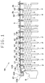
- FIG. 1 is a cross-sectional view illustrating the main part of a radiator
- FIG. 2 is a front view illustrating the radiator
- FIG. 3 is a front view of a core assembly.
- Radiator 1 for cooling engine cooling water, is referred to as an example of a heat exchanger.
- the radiator 1 comprises a core assembly 4 including a plurality of tubes 2 and a plurality of corrugated fins 3 both of which are alternately stacked, a pair of header plates 5 connected to the plurality of tubes 2 at respective ends thereof, an inlet tank 7 and an outlet tank 8 both of which include header tanks 6 fixed to the header plates 5 respectively, and a pair of side plates 9 disposed on both sides of the core assembly 4 for connecting the pair of header plates 5 to each other at the ends thereof.
- the components of the radiator 1 except for the header tanks 6, i.e., the core assembly 4 (including the tubes 2 and the corrugated fins 3), the header plates 5 and the side plates 9, are made of aluminum, which are integrally brazed in a furnace into the main body of the radiator 1.
- the header tanks 6 are made of resin, and are fixed to the header plates 5 of the brazed main body of the radiator 1 through packings (not illustrated).
- the tube 2 is made of a thin aluminum plate which is rolled and then seamed by means of welding into a tube having a crushed and elliptical cross section.
- the inside of the tube 2 forms a fluid passage 11 that allows the engine cooling water to flow therethrough.
- the surface of the tube 2 is clad with a brazing material.
- the corrugated fin 3 is made of a thin aluminum plate strip zigzaggedly formed by means of rolling.
- the air-flow part of the corrugated fin 3 is equipped with louvres (not illustrated) for higher heat exchange efficiency.
- the header plate 5 is made of an aluminum plate which is pressed into the required shape and then clad with a brazing material on one side thereof, the side which interfaces with the external surface of the header tank 6.
- the header plate 5 includes a plurality of press-fitting holes 12 into which the plurality of tubes 2 are press fitted.
- the header plate 5 has U-shaped grooves 13 at both distal end parts into which the end parts of the header tank 6 are inserted.
- the press-fitting holes 12 of this embodiment are formed to be open into the header tank 6 by a burring process.
- the outer wall 13a of the groove 13 is provided with a number of claws (not illustrated), which are intended to be folded after an open end of the header tank 6 is inserted into the groove 13 so that the header tank 6 can be fixed to the header plate 5.
- the side plate 9 is made of an aluminum plate which is pressed to have a U-shape cross section and then clad with a brazing material, at least on the side to which the corrugated fin 3 is to be connected.
- the end parts of the side plate 9 are provided with connecting parts 14, respectively which are pressed into a rough U-shape.
- the back part 14a of the connecting part 14 is to be connected to the back part of the inner wall 13b of the groove 13 of the header plate 5, and the outermost wall 14b of the connecting part 14 is to be connected to the opposite surface 5a of the header plate 5 facing the inner surface of the other header plate 5.
- the tubes 2 disposed near either side of the side plates 9 accounting for approximately 10% of the total tubes are flared to an angle of approximately 180°, the percentage of the tubes 2 that are flared to an angle of approximately 180° may be changed to an adequate percentage according to the weight of the core assembly 4, etc.
- the plurality of tubes 2 and the plurality of corrugated fins 3 are alternately stacked, and then side plates 9 are disposed at both sides thereof.
- the pair of header plates 5 are disposed at the end parts of the plurality of tubes 2, then the end parts of all the tubes 2 are press fitted into the respective press-fitting holes 12 in the header plates 5. Then the connecting parts 14 at the end parts of the pair of side plates 9 are contacted to the pair of header plates 5 (first process).
- the main body part 1a (FIG. 1) assembled in the first process (an assembly of the plurality of tubes 2, the plurality of corrugated fins 3, the pair of header plates 5 and the pair of side plates 9 illustrated in FIG. 3) is set into a tube widening device (not illustrated).
- the tube widening device press fits large flaring pins having an angle of approximately 180° into the engine cooling water passages 11 of the tubes 2 disposed near either of the side plates 9 and accounting for approximately 10% of all the tubes 2. Smaller flaring pins, having an angle within a range from approximately 60° to about 80° into the engine cooling water passages 11 of the remaining about 80% of the tubes 2 disposed in the central area of the core assembly 4 indicated by ⁇ in FIG. 3.
- the large widening parts 2a with a flare angle of approximately 180° are formed on the end parts of approximately 10% of the tubes 2 disposed near either end of the core assembly 4, and the small widening parts 2b with a flare angle within a range from approximately 60° to approximately 80° are formed on the end parts of approximately 80% of the tubes 2 disposed in the central area of the core assembly 4 (second process).
- the tube end widening device has disposed on its upper and lower sides the large flaring pins to be press fitted into the engine cooling water passages 11 at the end parts of approximately 10% of the tubes 2 disposed near either of the side plates 9 to widen the end parts of the above tubes 2 to an angle of 180° and the smaller flaring pins to be press fitted into the engine cooling water passages 11 at the end parts of approximately 80% of the tubes 2 disposed in the central part of the core assembly 4 to widen the end parts of the above tubes 2 to an angle within a range from 60° to 80.°°.
- the large flaring pins and the small flaring pins which are designed to widen the end parts of the tubes 2 to make the flared outer peripheries of the tubes 2 match the respective press fitting holes 12, comprise tip guiding parts to be inserted into the engine cooling water passages 11 to prevent the engine cooling water passages 11 from being narrowed during the widening process and widening parts for widening the end parts of the tubes 2 towards both sides. Between the large flaring pins and the small flaring pins are disposed spacers so that the intervals therebetween match the interval between the tubes 2.
- the tube end widening device is equipped with an upper supporter at the upper side for supporting the large flaring pins and the small flaring pins and a lower supporter at the lower side for supporting the larger flaring pins and the small flaring pins.
- At least one of the upper supporter and lower supporter is so provided as to be driven up/down by a driving means.
- the main body part 1a assembled in the first process. Then, either of the upper supporter or the lower supporter is driven by a predetermined amount for a driving stroke, and then subjected to a predetermined amount of load.
- the large widening parts 2a are formed at the end parts of approximately 10% of the tubes 2 disposed near either side of the core assembly 4 and the small widening parts 2b are formed at the end parts of approximately 80% of the tubes 2 disposed in the central part of the core assembly 4.
- the tube end widening device is equipped with a clamp for supporting the core assembly 4 from both sides of the pair of side plates 9 during the widening process.
- This clamp is applied to both sides of the core assembly 4 to protect the tubes 2 disposed near either side of the core assembly 4 and the pair of side plates 9 from deformation.
- the large widening parts 2a and the small widening parts 2b are formed at the end parts of all the tubes 2 in the second process.
- This arrangement prevents the header plates 5 at both sides from moving outwards.
- between the header plates 5 at both sides are disposed the pair of side plates 9 in contact with the above header plates 5.
- This arrangement can prevent the header plates 5 at both sides from moving inward. That is, even if some loads are applied to the main body part 1a from the outside, the assembled state achieved in the first process can be maintained.
- the header plate 5 to be supported by the jigs may be either of the header plate 5 forming the inlet tank 7 or the header plate 5 forming the outlet tank 8.
- brazing material clad on each component thereof melts. Then, the melted brazing material spreads to the contacting part of each component, forming a brazing core.
- the power of the press-fitting holes 12 to hold the tubes 2 decreases to such an extent that only the holding power of the press-fitting holes 12 can not resist the downward force due to the self-weight of the core assembly 4.
- the upper end of approximately 10% of the tubes 2 disposed near either side of the core assembly 4 are flared to an angle approximately 180°, even if the hardness of the tubes 2 is lowered, the flared angle will not be narrowed by the self-weight of the core assembly 4. This arrangement can protect the tubes 2 disposed near either side of the core assembly 4 from slipping down from the upper header plate 5.
- the pair of header plates 5 and the pair of side plates 9 can exactly be brazed and thereby the degradation in the strength of the radiator 1 can exactly be prevented by widening the end parts of approximately 10% of the tubes 2 disposed near either side of the core assembly 4 to an angle of approximately 180°, which is larger than the flared angle within a range from approximately 60° to 80° applied to the end parts of approximately 80% of the tubes 2 disposed in the central part of the core assembly 4.
- either one of the pair of header plates 5 can be supported by the carbon jig. This arrangement facilitates the handling of the main body part 1a during the manufacturing processes.
- the state of assembling achieved in the first process can be maintained, even if some loads are applied from the outside to the main body part 1a.
- This arrangement also facilitates the handling of the main body part 1a during the manufacturing processes.
- the header plate 5 disposed at the lower side will not come off from the tubes 2. This arrangement can prevent the occurrence of the defective brazing at the lower side.
- FIG. 4 depicts a cross-sectional view illustrating the main part of the radiator 1 according to the second embodiment of the present invention.
- the flared angle of approximately 10% of the tubes 2 disposed near either side of the core assembly 4 is set to an angle approximately 180° and the flared angle of remaining approximately 80% of the tubes 2 disposed in the central part of the core assembly 4 is set to an angle within a range from approximately 60° to approximately 80°.
- the flared angles of the end parts of the tubes 2 gradually decrease in the size of the angle as the tubes progress from the sides near the side plate 9 towards the center of the core assembly 4.
- the widening parts 2c of the tubes 2 near either side of the side plate 9 are flared to the largest angle of approximately 180°, while the widening parts 2d of the tubes 2 in the central part of the core assembly 4 are flared to the smallest angle of approximately 0°.
- the tubes 2 with large flared angles and the tubes 2 with small flared angles are alternately disposed every one or more than one tubes 2 or randomly disposed.
- more than three different flared angles are set and the tubes 2 with these three different flared angles respectively are alternately disposed every one or more than one tubes 2 or continuously or even randomly disposed.
- press-fitting holes 12 of the header plates 5 are formed to be open into the header tank 6 by a burring process, it is acceptable that the press-fitting holes 12 are formed into mere through holes.
- radiator 1 is used as an example of a heat exchanger
- header tanks 6 are made of a resin
- tank headers 6 are made of a metal and integrally brazed with other components including the cores 3.
Abstract
Description
- The present invention generally relates to a method for producing a heat exchanger and to the heat exchanger produced by the method. More particularly, the present invention relates to a stack type heat exchanger that is brazed when a header plate disposed at an upper side is supported by jigs and cores and to the method for producing the stack type heat exchanger.
- As illustrated in FIGS. 5 and 6, it is known to stack
cores 103 with a plurality oftubes 101 in order to form engine cooling water passages. Furthermore, it is known to assemble a plurality ofcorrugated fins 102 and connect a pair ofheader plates 104 to both ends oftubes 101, and also to connectheader plates 104 usingside plates 105.Cores 103 are hung from anupper header plate 104 in a downward direction.Upper header plate 104 is supported bycarbon jigs 106. An assembly including these structure is integrally brazed within a furnace. Eachtube 101 is lightly press fitted into each press-fitting hole 107 within the pair ofheader plates 104.Cores 103 are held betweenside plates 105 at both sides of the heat exchanger (in some cases,cores 103 are held betweenside plates 105 and bundled with wires, etc.). - When the assembly is brazed in this state, the brazing material clad on the surface of each
tube 101 melts and flows, whereby the width in the direction of the stack ofcorrugated fins 102 and tubes 101 (lateral direction) is reduced, and at the same time, the reaction force of thecorrugated fins 102,side plates 105, etc. is decreased in the high temperature condition associated with brazing. As a result, as illustrated in FIG. 7, a gap tl is formed between the back ofend side 105a ofside plate 105 and the back ofinner wall 108a ofU-shape groove 108 formed on the distal end part ofheader plate 104. - Furthermore, when the brazing material clad on the surface of each
tube 101 melts and flows, the diameter of eachtube 101 is reduced, and at the same time, due to the exposure to high temperatures, the press-fitting force of eachtube 101 press fits into each press-fitting hole 107 in theheader plate 104 is decreased, wherebycores 103 hung from theupper header plate 104 may slide down by due to their own weight. Ifcore 103 slides down fromupper header plate 104,side plates 105 also slide down withcores 103. As illustrated in FIG. 7, a gap t2 forms betweenoutermost part 105b ofside plate 105 and the back ofopposite surface 104a ofheader plate 104. - If the occurrence of at least one of the above gaps t1 and t2 can be prevented,
side plates 105 andheader plates 104 may be brazed to each other. If both gaps t1 and t2 occur, defects will be caused such thatside plates 105 andheader plates 104 are not brazed to each other, thus impairing the strength of the resulting heat exchanger. - Methods have been suggested to prevent
cores 103, etc. hung fromupper header plate 104 from sliding down due to their own weight. One possible alternative has been to flare the open end of each tube 101 (in other words, to widen the opening and increase the diameter thereof) press fit into each press-fitting hole 107 inheader plate 104. - Such a technique has been proposed in Japanese Unexamined Patent Publication No. 59-180295. According to this document, tube flaring pins are inserted into the open ends of each
tube 101 press fitted into each press-fitting hole 107 inheader plates 104, and the end parts of eachtube 101 are flared to an angle within a range from 20° to 30° to improve the connection force between each press-fitting hole 107 and the end parts of eachtube 101. - During the brazing process, as
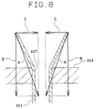
core 103 is hung fromupper header plate 104 through eachtube 101 press fitted into each press-fitting hole 107 inheader plate 104, as illustrated in FIG. 8, a force indicated by arrows A is applied to flared part oftube 101. This force (arrow A) is the resultant force made up of a vertical force (arrow B) and a horizontal force (arrow C). On the other hand, eachtube 101 is softened during the brazing process due to the high brazing temperature. As a result, the flared angle of the flared part of thetube 101 is narrowed by the vertical force applied to the flared part of tube 101 (arrow B). - If the flared angle of the flared part of the
tube 101 is narrowed during the brazing process in this way, thecore 103 hung from theupper header plate 104 will slide down due to its weight, whereby, as illustrated in FIG. 7, the gap t2 is formed between theoutermost part 105b of theside plate 105 and theopposite surface 104a of theheader plate 104. - Another method has been disclosed in United States Patent No. 4,700,469. According to this Patent, the end parts of each
tube 101 press fitted into the press-fittingholes 107 in theheader plates 104 are flared to an angle of approximately 180°. If the flared angle is set to approximately 180° in this way, any horizontal force will not cause part of thetube 101 to widen, even if thecore 103 is hung from theupper header plate 104 through eachtube 101. Accordingly, the widened angle of widening part of eachtube 101 will not be narrowed during the brazing process, whereby thecore 103 hung from theupper header plate 104 will not slide down due to its own weight. As a result, the gap t2 is not formed between theoutermost part 105b of theside plate 105 and theopposite surface 104a of theheader plate 104. - When the end parts of the
tubes 101 are flared to an angle of approximately 180°, considerably large loads are applied to thetube 101 and to theheader plate 104 supporting thetubes 101. According to the disclosure of United States Patent No. 4,700,469, the end parts of all thetubes 101 are flared to an angle of approximately 180°. Therefore, if the end parts of all thetubes 101 are flared to such an angle, considerably large loads had to be applied to all thetubes 101 and theheader plate 104 around therespective tubes 101. - The loads applied to the end parts of the
header plate 104 are supported by theside plates 105, which have a sufficiently high strength to support the load, and thetubes 101, which do not have a sufficiently high strength. However, loads applied to the central area of the assembly ofcores 103 are supported only by thetubes 101, which is not desirable. - For this reason, if the technique disclosed in the United States Patent No. 4,700,469 is applied, considerably large loads will be applied to the
tubes 101 disposed in the central area of the assembly of thecores 103. As a result, defects are caused such as the buckling of thetubes 101 disposed in the central area of the assembly of thecores 103 and warp deformation of theupper header plate 104. - In view of the above problem, it is an object of the present invention to provide a method for producing a heat exchanger which allows the header plates and the side plates to be securely brazed without any buckling of the tubes or deformation of the header plates and to provide a heat exchanger produced by this producing method.
- The present invention includes a method for producing a heat exchanger having cores stacked with a plurality of tubes having first and second end parts provided with engine cooling water passages therein and a plurality of corrugated fins, a pair of header plates including a plurality of press-fitting holes, and a pair of side plates disposed at sides of the cores for connecting the pair of header plates to each other in a state where the cores are held therebetween. The method includes press fitting the first and second end parts of the plurality of tubes into the press-fitting holes in the pair of header plates. The method further includes contacting end parts of the pair of side plates with the pair of head plates, thus forming a heat exchanger assembly. Also, the method includes flaring at least one of the first and second end parts of the tubes to be disposed on an upper side during blazing, wherein tubes disposed in a central parts of the header plate are flared to have a smaller degree than those tubes disposed proximate the side plates, thus preventing the tubes from sliding during blazing. Finally the method includes brazing the assembly within a furnace.
- This method produces a heat exchanger comprising a plurality of cores stacked with a plurality of tubes, each tube having first and second end parts, provided with engine cooling water passages therein and a plurality of corrugated fins zigzaggedly formed, a pair of header plates including a plurality of press-fitting holes into which the end parts of the plurality of tubes are press fitted and connected, and a pair of side plates disposed at sides of the plurality of cores for connecting the pair of header plates to each other in the state that the cores are held therebetween, wherein at least one end of the plurality of tubes to be press fitted into the press-fitting holes in the header plates is flared, and the flared angles of the end parts of the tubes disposed proximate the side plates is set to be larger than the flared angle of the end parts of the tubes disposed in a central part of the assembly of the cores.
- According to the method for producing a heat exchanger according to the present invention, a pair of header plates and a pair of side plates can be securely brazed without complicating the shapes of the components of the heat exchanger, such as header plates and side plates, by setting the flare angle of the end parts of the tubes disposed in the side plate areas to be larger than the flare angle of the end parts of the tubes disposed in the central part of the core assembly.
- In addition, as the flare angle of the end parts of the tubes disposed in the central part of the core assembly is set to be smaller than the flare angle of the end parts of the tubes disposed in the side plate areas, loads applied to the tubes disposed in the central part of the core assembly can be minimized. As a result, the buckling of the tubes disposed in the central part of the core assembly or the deformation of the header plate can be prevented, whereby the pair of header plates and the pair of side plates can be securely brazed.
- If the tubes are made thinner, the press fitting force of each tube press fitted into each press-fitting hole and the hardness of the tubes during the brazing process is further reduced. Accordingly, the a defect that the core, etc. hung from the upper header plate slides down due to its own weight during the brazing process can easily occur. By adopting the method according to the present invention, however, even if the tubes are made thinner, the sliding downward of the tubes disposed in the side plate areas during the brazing process is prevented, whereby the pair of header plates and the pair of side plates can be securely brazed.
- Other objects, features and characteristics of the present invention as well as the function of related parts will become apparent upon a study of the following detailed description, the appended claims and the drawings, all of which form a part of this specification. In the drawings:
- FIG. 1 is a cross-sectional view illustrating the main part of a radiator according to a first embodiment;
- FIG. 2 is a front view illustrating the radiator;
- FIG. 3 is a front view illustrating a core;
- FIG. 4 is a cross-sectional view illustrating the main part of a radiator according to a second embodiment;
- FIG. 5 is a cross-sectional view illustrating the main part of a heat exchanger of a known structure;
- FIG. 6 is a cross-sectional side view illustrating a heat exchanger during brazing process of a known structure;
- FIG. 7 is an illustrative view illustrates a defective part of a heat exchanger of a known structure; and
- FIG. 8 is an illustrative view illustrating the occurrence of a defect of the heat exchanger in a known structure.
- The method for producing a heat exchanger according to the present invention will be described based on the first embodiment referring to FIGS. 1, 2 and 3.
- FIGS. 1, 2 and 3 illustrate the first embodiment of the present invention. FIG. 1 is a cross-sectional view illustrating the main part of a radiator, FIG. 2 is a front view illustrating the radiator, and FIG. 3 is a front view of a core assembly.
- Radiator 1, for cooling engine cooling water, is referred to as an example of a heat exchanger. The radiator 1 comprises a
core assembly 4 including a plurality oftubes 2 and a plurality ofcorrugated fins 3 both of which are alternately stacked, a pair ofheader plates 5 connected to the plurality oftubes 2 at respective ends thereof, aninlet tank 7 and anoutlet tank 8 both of which includeheader tanks 6 fixed to theheader plates 5 respectively, and a pair ofside plates 9 disposed on both sides of thecore assembly 4 for connecting the pair ofheader plates 5 to each other at the ends thereof. The components of the radiator 1 except for theheader tanks 6, i.e., the core assembly 4 (including thetubes 2 and the corrugated fins 3), theheader plates 5 and theside plates 9, are made of aluminum, which are integrally brazed in a furnace into the main body of the radiator 1. Theheader tanks 6 are made of resin, and are fixed to theheader plates 5 of the brazed main body of the radiator 1 through packings (not illustrated). - The
tube 2 is made of a thin aluminum plate which is rolled and then seamed by means of welding into a tube having a crushed and elliptical cross section. The inside of thetube 2 forms afluid passage 11 that allows the engine cooling water to flow therethrough. The surface of thetube 2 is clad with a brazing material. - The
corrugated fin 3 is made of a thin aluminum plate strip zigzaggedly formed by means of rolling. The air-flow part of thecorrugated fin 3 is equipped with louvres (not illustrated) for higher heat exchange efficiency. - The
header plate 5 is made of an aluminum plate which is pressed into the required shape and then clad with a brazing material on one side thereof, the side which interfaces with the external surface of theheader tank 6. Theheader plate 5 includes a plurality of press-fittingholes 12 into which the plurality oftubes 2 are press fitted. Theheader plate 5 hasU-shaped grooves 13 at both distal end parts into which the end parts of theheader tank 6 are inserted. The press-fittingholes 12 of this embodiment are formed to be open into theheader tank 6 by a burring process. Theouter wall 13a of thegroove 13 is provided with a number of claws (not illustrated), which are intended to be folded after an open end of theheader tank 6 is inserted into thegroove 13 so that theheader tank 6 can be fixed to theheader plate 5. - The
side plate 9 is made of an aluminum plate which is pressed to have a U-shape cross section and then clad with a brazing material, at least on the side to which thecorrugated fin 3 is to be connected. In addition, the end parts of theside plate 9 are provided with connectingparts 14, respectively which are pressed into a rough U-shape. Theback part 14a of the connectingpart 14 is to be connected to the back part of theinner wall 13b of thegroove 13 of theheader plate 5, and theoutermost wall 14b of the connectingpart 14 is to be connected to theopposite surface 5a of theheader plate 5 facing the inner surface of theother header plate 5. - Of all the
tubes 2 press fitted into theheader plate 5, thosetubes 2 disposed near either side of theheader plates 5, which account for approximately 10% of the tubes, i.e. thetubes 2 nearside plates 9 as indicated by α in FIG. 3, are provided at the ends with large widenedparts 2a, which have been flared to an angle of approximately 180° by large flaring pins (not illustrated). On the other hand, thosetubes 2 disposed in the central part of thecore assembly 4 and accounting for approximately 80% of all thetubes 2, i.e. thosetubes 2 indicated by β in FIG. 3, are provided at the ends with small wideningparts 2b, which have been flared to only an angle within a range from approximately 60° to about 80° by flaring pins (not illustrated) smaller than those which operated upon the flaring pins in the range α. The respective outer peripheries of thelarge widening parts 2a and small wideningparts 2b fit the respective press-fittingholes 12. Now, the pair of theside plates 9 are in contact at the ends with the pair ofheader plates 5 with thelarge widening parts 2a and the small wideningparts 2b formed integrally therewith. In this state, the main part of the radiator 1 is brazed. Although thetubes 2 disposed near either side of theside plates 9 accounting for approximately 10% of the total tubes are flared to an angle of approximately 180°, the percentage of thetubes 2 that are flared to an angle of approximately 180° may be changed to an adequate percentage according to the weight of thecore assembly 4, etc. - The manufacturing processes of the above radiator 1 will now be described.
- First, the plurality of
tubes 2 and the plurality ofcorrugated fins 3 are alternately stacked, and thenside plates 9 are disposed at both sides thereof. Second, the pair ofheader plates 5 are disposed at the end parts of the plurality oftubes 2, then the end parts of all thetubes 2 are press fitted into the respective press-fittingholes 12 in theheader plates 5. Then the connectingparts 14 at the end parts of the pair ofside plates 9 are contacted to the pair of header plates 5 (first process). - The
main body part 1a (FIG. 1) assembled in the first process (an assembly of the plurality oftubes 2, the plurality ofcorrugated fins 3, the pair ofheader plates 5 and the pair ofside plates 9 illustrated in FIG. 3) is set into a tube widening device (not illustrated). The tube widening device press fits large flaring pins having an angle of approximately 180° into the engine coolingwater passages 11 of thetubes 2 disposed near either of theside plates 9 and accounting for approximately 10% of all thetubes 2. Smaller flaring pins, having an angle within a range from approximately 60° to about 80° into the engine coolingwater passages 11 of the remaining about 80% of thetubes 2 disposed in the central area of thecore assembly 4 indicated by β in FIG. 3. As a result, thelarge widening parts 2a with a flare angle of approximately 180° are formed on the end parts of approximately 10% of thetubes 2 disposed near either end of thecore assembly 4, and the small wideningparts 2b with a flare angle within a range from approximately 60° to approximately 80° are formed on the end parts of approximately 80% of thetubes 2 disposed in the central area of the core assembly 4 (second process). - A description of the tube end widening device used in the second process is now provided. The tube end widening device has disposed on its upper and lower sides the large flaring pins to be press fitted into the engine cooling
water passages 11 at the end parts of approximately 10% of thetubes 2 disposed near either of theside plates 9 to widen the end parts of theabove tubes 2 to an angle of 180° and the smaller flaring pins to be press fitted into the engine coolingwater passages 11 at the end parts of approximately 80% of thetubes 2 disposed in the central part of thecore assembly 4 to widen the end parts of theabove tubes 2 to an angle within a range from 60° to 80.°°. The large flaring pins and the small flaring pins, which are designed to widen the end parts of thetubes 2 to make the flared outer peripheries of thetubes 2 match the respective press fitting holes 12, comprise tip guiding parts to be inserted into the engine coolingwater passages 11 to prevent the engine coolingwater passages 11 from being narrowed during the widening process and widening parts for widening the end parts of thetubes 2 towards both sides. Between the large flaring pins and the small flaring pins are disposed spacers so that the intervals therebetween match the interval between thetubes 2. - In addition, the tube end widening device is equipped with an upper supporter at the upper side for supporting the large flaring pins and the small flaring pins and a lower supporter at the lower side for supporting the larger flaring pins and the small flaring pins. At least one of the upper supporter and lower supporter is so provided as to be driven up/down by a driving means. Between the large and small flaring pins at the upper side and those at the lower side is placed the
main body part 1a assembled in the first process. Then, either of the upper supporter or the lower supporter is driven by a predetermined amount for a driving stroke, and then subjected to a predetermined amount of load. By this process, thelarge widening parts 2a are formed at the end parts of approximately 10% of thetubes 2 disposed near either side of thecore assembly 4 and the small wideningparts 2b are formed at the end parts of approximately 80% of thetubes 2 disposed in the central part of thecore assembly 4. - Here, the tube end widening device is equipped with a clamp for supporting the
core assembly 4 from both sides of the pair ofside plates 9 during the widening process. This clamp is applied to both sides of thecore assembly 4 to protect thetubes 2 disposed near either side of thecore assembly 4 and the pair ofside plates 9 from deformation. - In this embodiment, the
large widening parts 2a and the small wideningparts 2b are formed at the end parts of all thetubes 2 in the second process. This arrangement prevents theheader plates 5 at both sides from moving outwards. In addition, between theheader plates 5 at both sides are disposed the pair ofside plates 9 in contact with theabove header plates 5. This arrangement can prevent theheader plates 5 at both sides from moving inward. That is, even if some loads are applied to themain body part 1a from the outside, the assembled state achieved in the first process can be maintained. - Only one of the
header plates 5 is supported by carbon jigs, such as those described with reference to FIG. 6 (refer to thejigs 106 described), and thecore assembly 4, etc. are hung from theheader plate 5 supported by the jigs. The assembledmain body part 1a arranged in the above state is then placed into a furnace and heated to a temperature high enough to melt the brazing material thereon to integrally braze themain body part 1a (brazing process). In this embodiment, as the end parts of thetubes 2 are flared, theheader plate 5 to be supported by the jigs may be either of theheader plate 5 forming theinlet tank 7 or theheader plate 5 forming theoutlet tank 8. - When the
main body part 1a is exposed to a high temperature in the furnace, the brazing material clad on each component thereof melts. Then, the melted brazing material spreads to the contacting part of each component, forming a brazing core. - On the other hand, when the
main body part 1a is exposed to a high temperature in the furnace, due to the lowering of the hardness of thetubes 2, the power of the press-fittingholes 12 to hold thetubes 2 decreases to such an extent that only the holding power of the press-fittingholes 12 can not resist the downward force due to the self-weight of thecore assembly 4. However, as the upper end of approximately 10% of thetubes 2 disposed near either side of thecore assembly 4 are flared to an angle approximately 180°, even if the hardness of thetubes 2 is lowered, the flared angle will not be narrowed by the self-weight of thecore assembly 4. This arrangement can protect thetubes 2 disposed near either side of thecore assembly 4 from slipping down from theupper header plate 5. As a result, the contacting state of the contactingparts 14 at the end parts of theside plates 9 disposed on both sides of thecore assembly 4 with the pair ofheader plate 5 is maintained, whereby the pair ofheader plates 5 and the pair ofside plates 9 are exactly be brazed. - As mentioned above, without complicating the shape of the components of the radiator 1 including the
header plates 5 and theside plates 9, the pair ofheader plates 5 and the pair ofside plates 9 can exactly be brazed and thereby the degradation in the strength of the radiator 1 can exactly be prevented by widening the end parts of approximately 10% of thetubes 2 disposed near either side of thecore assembly 4 to an angle of approximately 180°, which is larger than the flared angle within a range from approximately 60° to 80° applied to the end parts of approximately 80% of thetubes 2 disposed in the central part of thecore assembly 4. - On the other hand, as the end parts of approximately 80% of the
tubes 2 displaced in the central part of thecore assembly 4 are flared to an angle within an range from approximately 60° to 80°, which is smaller than the flared angle for thetubes 2 disposed near either side of theside plates 9, only small loads are required for widening approximately 80% of thetubes 2 disposed in the central part of thecore assembly 4. As a result, the buckling of thetubes 2 disposed in the central part of thecore assembly 4 or the deformation of theheader plates 5 can be prevented. - As only the end parts of the
tubes 2 are flared and thetubes 2 are not flared within the press-fittingholes 12, only small loads are required for widening the end parts of thetubes 2. That is, if thetubes 2 should be flared within the press-fittingholes 12, as larger loads will have to be applied to thetubes 2, defects such as the buckling of thetubes 2 would be caused. In this embodiment, however, as any application of large loads is not required to thetubes 2, any buckling of thetubes 2 will not be caused. - By widening the end parts of the
tubes 2, either one of the pair ofheader plates 5 can be supported by the carbon jig. This arrangement facilitates the handling of themain body part 1a during the manufacturing processes. - Also, by widening the end parts of the
tubes 2, the state of assembling achieved in the first process can be maintained, even if some loads are applied from the outside to themain body part 1a. This arrangement also facilitates the handling of themain body part 1a during the manufacturing processes. - Furthermore, by widening the end parts of the
tubes 2, even if themain body part 1a is exposed to a high temperature within a furnace, theheader plate 5 disposed at the lower side will not come off from thetubes 2. This arrangement can prevent the occurrence of the defective brazing at the lower side. - FIG. 4 depicts a cross-sectional view illustrating the main part of the radiator 1 according to the second embodiment of the present invention.
- In the above first embodiment, a case was presented where the flared angle of approximately 10% of the
tubes 2 disposed near either side of thecore assembly 4 is set to an angle approximately 180° and the flared angle of remaining approximately 80% of thetubes 2 disposed in the central part of thecore assembly 4 is set to an angle within a range from approximately 60° to approximately 80°. In this embodiment, however, as illustrated in FIG. 4, the flared angles of the end parts of thetubes 2 gradually decrease in the size of the angle as the tubes progress from the sides near theside plate 9 towards the center of thecore assembly 4. That is, the wideningparts 2c of thetubes 2 near either side of theside plate 9 are flared to the largest angle of approximately 180°, while the wideningparts 2d of thetubes 2 in the central part of thecore assembly 4 are flared to the smallest angle of approximately 0°. - In the above embodiments, the case was presented where the end parts of the
tubes 2 disposed near either side of thecore assembly 4 are flared to larger angles, while the end parts of thetubes 2 disposed in the central part of thecore assembly 4 are flared to smaller angles. However, it is acceptable that thetubes 2 with large flared angles and thetubes 2 with small flared angles are alternately disposed every one or more than onetubes 2 or randomly disposed. Alternatively, it is also acceptable that more than three different flared angles are set and thetubes 2 with these three different flared angles respectively are alternately disposed every one or more than onetubes 2 or continuously or even randomly disposed. - Also, a case was presented where the press-fitting
holes 12 of theheader plates 5 are formed to be open into theheader tank 6 by a burring process, it is acceptable that the press-fittingholes 12 are formed into mere through holes. - Also, although a case was presented where both end parts of each
tube 2 are flared, it is acceptable that only one of the end parts of thetubes 2, to be brazed to theupper header plate 5, are flared. - Furthermore, although the radiator 1 is used as an example of a heat exchanger, any type of heat exchanger in which tubes and corrugated fins are alternately stacked, such as exchanger with heater cores or refrigerating cycles, may be used instead.
- Moreover, although the case has been described above where the
header tanks 6 are made of a resin, it is acceptable that thetank headers 6 are made of a metal and integrally brazed with other components including thecores 3.
Claims (17)
- A method for producing a heat exchanger 1 having cores 4 stacked with a plurality of tubes 2 having first and second end parts provided with engine cooling water passages 11 therein and a plurality of corrugated fins 3, a pair of header plates 5 including a plurality of press-fitting holes 12, and a pair of side plates 9 disposed at sides of said cores 4 for connecting said pair of header plates 5 to each other in a state where said cores 4 are held therebetween, said method comprising the steps of:
press fitting said first and second end parts of said plurality of tubes 2 into said press-fitting holes 12 in said pair of header plates 5;
contacting end parts of said pair of side plates 9 with said pair of header plates 5, thus forming a heat exchanger assembly;
flaring at least one of said first and second end parts to be disposed on an upper side during blazing, wherein tubes 2 disposed in a central parts of said header plate 5 are flared to have a smaller degree than those tubes disposed proximate said side plates 9, thus preventing said tubes 2 from sliding during blazing.
brazing said assembly within a furnace. - The method for producing a heat exchanger according to claim 1, further comprising the step of between said flaring step and said blazing step, supporting one of said header plates 5 with jigs in such a manner so as to hang down an assembly consisting of said cores 4, said pair of header plates 5 and said side plates 9.
- The method for producing a heat exchanger according to claim 1, wherein said flaring step includes flaring said plurality of tubes 2 such that tubes 2 disposed in a central part have a flared angle that gradually increases as the tubes 2 become closer to said side plates 9.
- The method for producing a heat exchanger according to claim 1, further comprising the step of between said flaring step and said blazing step, supporting one of said header plates 9 with jigs in such a manner so as to hang down an assembly consisting of said cores 4, said pair of header plates 5 and said side plates 9.
- The method for producing a heat exchanger according to claim 1, wherein said flaring step includes flaring the tubes 2 in the central part such that a mean value of the flared angles of the end parts is smaller than a mean value of the flared angles of the end parts of the tubes 2 disposed proximate said side plates 9.
- The method for producing a heat exchanger according to claim 1, further comprising the step of providing at least one tube proximate said side plates 9, before said press-fitting step, said at least one tube having a flared angle greater than a mean value of the flared angles of said tubes 2 disposed in said central part.
- The method for producing a heat exchanger according to claim 1, further comprising the step of providing at least one tube in said central part, before said press-fitting step, said at least one tube 2 having a flared angle smaller than a mean value of the flared angles of the tubes 2 disposed proximate said side plates 9.
- The method for producing a heat exchanger according to claim 1, wherein said flaring step includes flaring said end parts of said tubes 2 disposed in said central part such that they have a flared angle between about 60° to about 80°.
- The method for producing a heat exchanger according to claim 8, wherein said flaring step includes flaring said end parts of the tubes 2 disposed in proximate said side plate 9 such that they have a flared angle of approximately 180°.
- The method for producing a heat exchanger according to claim 1, further comprising the step of providing side plate areas proximate said side plate 9 such that each side plate area contains approximately 10% of all the tubes 2 and the tubes 2 disposed in said central part account for approximately 80% of all the tubes 2.
- A method for producing a heat exchanger having cores stacked with a plurality of tubes 2 having first and second end parts provided with engine cooling water passages 11 therein and a plurality of corrugated fins 3, a pair of header plates 5 including a plurality of press-fitting holes 12, and a pair of side plates 9 disposed at both sides of said cores 4 for connecting said pair of header plates 5 to each other in the state where said cores 4 are held therebetween, said method comprising the steps of:
press fitting said first and second end parts of said plurality of tubes 2 into said press-fitting holes 12 in said pair of header plates 5;
contacting end parts of said pair of side plates 9 with said pair of head plates 9, thus forming a heat exchanger assembly;
flaring at least one of said first and second end parts of said tubes 2 to be disposed on an upper side during blazing, wherein tubes 2 disposed in a first group have a larger flared angle than tubes 2 to disposed in a second group, said first and second groups preventing said tubes from sliding down from said header plate 5;
brazing said assembly within a furnace. - The method for producing a heat exchanger according to claim 11, comprising the step of inserting flaring pins into said tubes 2 to be set at an upper side during blazing.
- The method for producing a heat exchanger according to claim 11, wherein said flaring step includes providing said first group proximate each said side plate 9 and said second group at a central area of the assembly of said cores 4.
- The method for producing a heat exchanger according to claim 11, wherein said flaring step includes flaring the end parts of said first group such that said tubes 2 have a flared angle of approximately 180° and the end parts of said second group such that said tubes 2 have flared angles within a range from about 60° to about 80°.
- The method for producing a heat exchanger according to claim 13, wherein said flaring step includes providing tubes 2 in said first group accounting for approximately 20% of all the tubes and said providing tubes 2 in said second group accounting for approximately 80% of all the tubes 2.
- A heat exchanger comprising:
a plurality of cores 4 stacked with a plurality of tubes 2, each tube having first and second end parts, provided with engine cooling water passages 11 therein and a plurality of corrugated fins 3 zigzaggedly formed;
a pair of header plates 5 including a plurality of press-fitting holes 12 into which said end parts of said plurality of tubes 2 are press fitted and connected; and
a pair of side plates 9 disposed at sides of said plurality of cores 4 for connecting said pair of header plates 5 to each other in the state that said cores 4 are held therebetween;
wherein at least one end of said plurality of tubes 2 to be press fitted into the press-fitting holes 12 in the header plates 5 is flared, and the flared angles of the end parts of the tubes 2 disposed proximate said side plates 9 is set to be larger than the flared angle of the end parts of the tubes 2 disposed in a central part of the assembly of said cores 4. - A method for forming a stacked type heat exchanger to be blazed, comprising the steps of:
providing header plates having a plurality of press-fitting holes 12;
providing a plurality of tubes 2 having end parts;
press-fitting said end parts of said tubes 2 into said press-fitting holes 12; and
flaring said end parts disposed in a central area of said plurality of tubes 2, said tubes 2 in said center area being flared to an angle smaller than an angle to which tubes 2 disposed surrounding said central area are flared.
Applications Claiming Priority (4)
| Application Number | Priority Date | Filing Date | Title |
|---|---|---|---|
| JP21778593 | 1993-09-01 | ||
| JP217785/93 | 1993-09-01 | ||
| JP158958/94 | 1994-07-11 | ||
| JP06158958A JP3125834B2 (en) | 1993-09-01 | 1994-07-11 | Heat exchanger and method of manufacturing the same |
Publications (2)
| Publication Number | Publication Date |
|---|---|
| EP0641986A1 true EP0641986A1 (en) | 1995-03-08 |
| EP0641986B1 EP0641986B1 (en) | 1997-04-23 |
Family
ID=26485919
Family Applications (1)
| Application Number | Title | Priority Date | Filing Date |
|---|---|---|---|
| EP94113689A Expired - Lifetime EP0641986B1 (en) | 1993-09-01 | 1994-09-01 | Heat exchanger and method for manufacturing thereof |
Country Status (6)
| Country | Link |
|---|---|
| US (1) | US5457885A (en) |
| EP (1) | EP0641986B1 (en) |
| JP (1) | JP3125834B2 (en) |
| CN (1) | CN1074531C (en) |
| AU (1) | AU684091B2 (en) |
| DE (1) | DE69402786T2 (en) |
Cited By (4)
| Publication number | Priority date | Publication date | Assignee | Title |
|---|---|---|---|---|
| EP0802386A1 (en) * | 1996-04-17 | 1997-10-22 | Sanden Corporation | Multi-tube heat exchanger |
| DE19757034A1 (en) * | 1997-12-20 | 1999-06-24 | Behr Gmbh & Co | Heat exchanger |
| DE102006002932A1 (en) * | 2006-01-21 | 2007-07-26 | Modine Manufacturing Co., Racine | Heat exchanger tube has internal chamber extends from center of tube past location to interior surface of second narrow side |
| US8177932B2 (en) | 2009-02-27 | 2012-05-15 | International Mezzo Technologies, Inc. | Method for manufacturing a micro tube heat exchanger |
Families Citing this family (34)
| Publication number | Priority date | Publication date | Assignee | Title |
|---|---|---|---|---|
| US6178292B1 (en) | 1997-02-06 | 2001-01-23 | Denso Corporation | Core unit of heat exchanger having electric heater |
| US6249968B1 (en) * | 1999-08-25 | 2001-06-26 | Visteon Global Technologies, Inc. | Method of making a robust gosper fin heat exchanger |
| IT1319494B1 (en) * | 2000-11-30 | 2003-10-20 | Nuovo Pignone Spa | TUBE PLATE FOR TUBE BANDS FOR CHEMICAL REACTORS AND HEAT EXCHANGERS IN GENERAL |
| DE10103570A1 (en) * | 2001-01-26 | 2002-08-01 | Modine Mfg Co | Heat exchangers and manufacturing processes |
| DE10114078A1 (en) * | 2001-03-22 | 2002-09-26 | Modine Mfg Co | Heat exchangers and manufacturing processes |
| DE10147192A1 (en) | 2001-09-25 | 2003-04-17 | Modine Mfg Co | Heat exchanger with a finned flat tube block and manufacturing process |
| US6786275B2 (en) * | 2002-05-23 | 2004-09-07 | Valeo Engine Cooling | Heat exchanger header assembly |
| JP2005121350A (en) * | 2003-05-29 | 2005-05-12 | Denso Corp | Heat exchanger and method for manufacturing it |
| DE102004029090A1 (en) * | 2003-06-20 | 2005-01-27 | Denso Corp., Kariya | Intermediate automotive heat exchanger production comprises application of solder paste to component parts and two-stage heating |
| US8281489B2 (en) * | 2006-01-19 | 2012-10-09 | Modine Manufacturing Company | Flat tube, flat tube heat exchanger, and method of manufacturing same |
| US8683690B2 (en) * | 2006-01-19 | 2014-04-01 | Modine Manufacturing Company | Flat tube, flat tube heat exchanger, and method of manufacturing same |
| US20090019696A1 (en) * | 2006-01-19 | 2009-01-22 | Werner Zobel | Flat tube, flat tube heat exchanger, and method of manufacturing same |
| US8434227B2 (en) | 2006-01-19 | 2013-05-07 | Modine Manufacturing Company | Method of forming heat exchanger tubes |
| US8191258B2 (en) * | 2006-01-19 | 2012-06-05 | Modine Manufacturing Company | Flat tube, flat tube heat exchanger, and method of manufacturing same |
| US8091621B2 (en) * | 2006-01-19 | 2012-01-10 | Modine Manufacturing Company | Flat tube, flat tube heat exchanger, and method of manufacturing same |
| JP2009524003A (en) * | 2006-01-19 | 2009-06-25 | モーディーン・マニュファクチャリング・カンパニー | Flat tube, flat tube heat exchanger, and method for manufacturing the same |
| US8438728B2 (en) * | 2006-01-19 | 2013-05-14 | Modine Manufacturing Company | Flat tube, flat tube heat exchanger, and method of manufacturing same |
| US20090014165A1 (en) * | 2006-01-19 | 2009-01-15 | Werner Zobel | Flat tube, flat tube heat exchanger, and method of manufacturing same |
| US7921559B2 (en) * | 2006-01-19 | 2011-04-12 | Modine Manufacturing Company | Flat tube, flat tube heat exchanger, and method of manufacturing same |
| DE102007004993A1 (en) | 2007-02-01 | 2008-08-07 | Modine Manufacturing Co., Racine | Production process for flat tubes and roller mill |
| WO2010048553A2 (en) * | 2008-10-23 | 2010-04-29 | Kesseli James B | Window system for a solar receiver and method and solar receiver system employing same |
| US20100175862A1 (en) * | 2009-01-14 | 2010-07-15 | Franklin David A | Brazed aluminum heat exchanger with split core arrangement |
| DE102010023384B4 (en) | 2010-06-10 | 2014-08-28 | Modine Manufacturing Co. | Manufacturing process, in particular for pipes and tear-off device |
| ES2623927T3 (en) * | 2010-12-21 | 2017-07-12 | Carrier Corporation | Automated brazing system with first and second burner groups |
| CN102705967A (en) * | 2011-03-28 | 2012-10-03 | 乐金电子(天津)电器有限公司 | Bottom plate of heat exchanger |
| DE102012017130B4 (en) * | 2012-09-01 | 2016-06-16 | Man Diesel & Turbo Se | Laser Rohreinschweißen |
| US9664450B2 (en) | 2013-04-24 | 2017-05-30 | Dana Canada Corporation | Fin support structures for charge air coolers |
| DE102013212939A1 (en) | 2013-07-03 | 2015-01-08 | Behr Gmbh & Co. Kg | Production method for a heat exchanger and tool for producing the heat exchanger |
| JP5953323B2 (en) * | 2014-02-14 | 2016-07-20 | 株式会社ティラド | Heat exchanger |
| CN110712004A (en) * | 2019-09-24 | 2020-01-21 | 福建聚光精密件制造有限公司 | Machining equipment and machining method for bell-mouth copper pipe |
| US11512800B2 (en) * | 2020-08-24 | 2022-11-29 | Rheem Manufacturing Company | Method of forming assembly between panel and tube |
| CN111843085B (en) * | 2020-09-07 | 2024-03-12 | 贵州永红散热器有限责任公司 | Method and tool for improving welding rate of flanging hole of nozzle and rib plate |
| US11924996B2 (en) * | 2020-09-30 | 2024-03-05 | Coolit Systems, Inc. | Liquid-cooling devices, and systems, to cool multi-chip modules |
| CN113188362B (en) * | 2021-05-11 | 2022-04-12 | 浙江银轮新能源热管理系统有限公司 | Shell and heat exchanger |
Citations (2)
| Publication number | Priority date | Publication date | Assignee | Title |
|---|---|---|---|---|
| DE2320866A1 (en) * | 1972-04-26 | 1973-11-08 | Chausson Usines Sa | REINFORCEMENT ARRANGEMENT FOR HEAT EXCHANGER |
| US4813112A (en) * | 1982-04-16 | 1989-03-21 | Societe Anonyme Des Usines Chausson | Method for reinforcing by means of small plates at least end rows of tubes engaged into tube end plates for constituting a heat exchanger |
Family Cites Families (5)
| Publication number | Priority date | Publication date | Assignee | Title |
|---|---|---|---|---|
| US3972371A (en) * | 1972-04-26 | 1976-08-03 | Societe Anonyme Des Usines Chausson | Tube and tube-plate assembly |
| JPS59180295A (en) * | 1983-03-30 | 1984-10-13 | Nippon Denso Co Ltd | Heat exchanger and its manufacturing method |
| US4730669A (en) * | 1986-02-03 | 1988-03-15 | Long Manufacturing Ltd. | Heat exchanger core construction utilizing a diamond-shaped tube-to-header joint configuration |
| US4700469A (en) * | 1986-03-24 | 1987-10-20 | General Motors Corporation | Detachable clamp for fixturing heat exchanger core assemblies for brazing in combination with the heat exchanger core |
| FR2674321B1 (en) * | 1991-03-20 | 1993-06-04 | Valeo Thermique Moteur Sa | HEAT EXCHANGER WITH MULTIPLE ROWS OF TUBES, PARTICULARLY FOR A MOTOR VEHICLE. |
-
1994
- 1994-07-11 JP JP06158958A patent/JP3125834B2/en not_active Expired - Fee Related
- 1994-08-31 US US08/299,019 patent/US5457885A/en not_active Expired - Lifetime
- 1994-09-01 EP EP94113689A patent/EP0641986B1/en not_active Expired - Lifetime
- 1994-09-01 AU AU71628/94A patent/AU684091B2/en not_active Ceased
- 1994-09-01 CN CN94116883.2A patent/CN1074531C/en not_active Expired - Fee Related
- 1994-09-01 DE DE69402786T patent/DE69402786T2/en not_active Expired - Lifetime
Patent Citations (2)
| Publication number | Priority date | Publication date | Assignee | Title |
|---|---|---|---|---|
| DE2320866A1 (en) * | 1972-04-26 | 1973-11-08 | Chausson Usines Sa | REINFORCEMENT ARRANGEMENT FOR HEAT EXCHANGER |
| US4813112A (en) * | 1982-04-16 | 1989-03-21 | Societe Anonyme Des Usines Chausson | Method for reinforcing by means of small plates at least end rows of tubes engaged into tube end plates for constituting a heat exchanger |
Cited By (5)
| Publication number | Priority date | Publication date | Assignee | Title |
|---|---|---|---|---|
| EP0802386A1 (en) * | 1996-04-17 | 1997-10-22 | Sanden Corporation | Multi-tube heat exchanger |
| DE19757034A1 (en) * | 1997-12-20 | 1999-06-24 | Behr Gmbh & Co | Heat exchanger |
| DE102006002932A1 (en) * | 2006-01-21 | 2007-07-26 | Modine Manufacturing Co., Racine | Heat exchanger tube has internal chamber extends from center of tube past location to interior surface of second narrow side |
| DE102006002932B4 (en) | 2006-01-21 | 2023-05-04 | Innerio Heat Exchanger GmbH | Heat exchangers and manufacturing processes for heat exchangers |
| US8177932B2 (en) | 2009-02-27 | 2012-05-15 | International Mezzo Technologies, Inc. | Method for manufacturing a micro tube heat exchanger |
Also Published As
| Publication number | Publication date |
|---|---|
| US5457885A (en) | 1995-10-17 |
| JP3125834B2 (en) | 2001-01-22 |
| AU684091B2 (en) | 1997-12-04 |
| EP0641986B1 (en) | 1997-04-23 |
| CN1074531C (en) | 2001-11-07 |
| DE69402786D1 (en) | 1997-05-28 |
| AU7162894A (en) | 1995-03-16 |
| JPH07116831A (en) | 1995-05-09 |
| CN1104762A (en) | 1995-07-05 |
| DE69402786T2 (en) | 1997-07-31 |
Similar Documents
| Publication | Publication Date | Title |
|---|---|---|
| US5457885A (en) | Heat exchanger and method for producing the same | |
| US6061904A (en) | Heat exchanger and method for manufacturing the same | |
| US5307870A (en) | Heat exchanger | |
| US6305465B1 (en) | Double heat exchanger having condenser core and radiator core | |
| EP1691160A1 (en) | Heat exchanger | |
| EP0881449A2 (en) | Refrigerant tubes for heat exchangers | |
| EP1030753B1 (en) | Method for assembling a heat exchanger | |
| WO2005098339A1 (en) | Heat exchanger having an improved baffle | |
| EP1643201B1 (en) | A heat exchanger assembly for a motor vehicle | |
| US8069911B2 (en) | Radiator with built-in oil cooler | |
| JP3974605B2 (en) | Header for heat exchanger | |
| US6206089B1 (en) | Heat exchanger and method for manufacturing the same | |
| JP3951812B2 (en) | Metal plate for flat tube manufacturing, flat tube and flat tube manufacturing method | |
| EP0384612A2 (en) | In tank oil cooler | |
| JP4043208B2 (en) | Heat exchanger | |
| EP0798530B1 (en) | Heat exchanger | |
| EP0805331A2 (en) | Multi-tube heat exchanger | |
| CA2219066A1 (en) | Humped plate fin heat exchanger | |
| US7036570B2 (en) | Multiple row heat exchanger using “end-to-end” or “tube touching” positioning of the tubes for row spacing | |
| JP3947833B2 (en) | Heat exchanger | |
| EP0683372A1 (en) | Heat exchanger and method of making heat exchangers | |
| JP2930434B2 (en) | Batch brazing method of connecting pipes for entrance and exit in heat exchangers with brazing specifications | |
| CA2410323A1 (en) | Flat-round joint in a "ct" or "serpentine" fin core | |
| GB2320957A (en) | Heat exchanger and header | |
| JP2001263976A (en) | Heat exchanger |
Legal Events
| Date | Code | Title | Description |
|---|---|---|---|
| PUAI | Public reference made under article 153(3) epc to a published international application that has entered the european phase |
Free format text: ORIGINAL CODE: 0009012 |
|
| AK | Designated contracting states |
Kind code of ref document: A1 Designated state(s): DE FR GB IT |
|
| 17P | Request for examination filed |
Effective date: 19950210 |
|
| 17Q | First examination report despatched |
Effective date: 19951017 |
|
| GRAG | Despatch of communication of intention to grant |
Free format text: ORIGINAL CODE: EPIDOS AGRA |
|
| GRAH | Despatch of communication of intention to grant a patent |
Free format text: ORIGINAL CODE: EPIDOS IGRA |
|
| GRAH | Despatch of communication of intention to grant a patent |
Free format text: ORIGINAL CODE: EPIDOS IGRA |
|
| RAP1 | Party data changed (applicant data changed or rights of an application transferred) |
Owner name: DENSO CORPORATION |
|
| GRAA | (expected) grant |
Free format text: ORIGINAL CODE: 0009210 |
|
| AK | Designated contracting states |
Kind code of ref document: B1 Designated state(s): DE FR GB IT |
|
| ITF | It: translation for a ep patent filed |
Owner name: RACHELI & C. S.R.L. |
|
| REF | Corresponds to: |
Ref document number: 69402786 Country of ref document: DE Date of ref document: 19970528 |
|
| ET | Fr: translation filed | ||
| PLBE | No opposition filed within time limit |
Free format text: ORIGINAL CODE: 0009261 |
|
| STAA | Information on the status of an ep patent application or granted ep patent |
Free format text: STATUS: NO OPPOSITION FILED WITHIN TIME LIMIT |
|
| 26N | No opposition filed | ||
| REG | Reference to a national code |
Ref country code: GB Ref legal event code: 746 Effective date: 19980824 |
|
| REG | Reference to a national code |
Ref country code: GB Ref legal event code: IF02 |
|
| PGFP | Annual fee paid to national office [announced via postgrant information from national office to epo] |
Ref country code: IT Payment date: 20100914 Year of fee payment: 17 |
|
| PGFP | Annual fee paid to national office [announced via postgrant information from national office to epo] |
Ref country code: FR Payment date: 20110922 Year of fee payment: 18 Ref country code: DE Payment date: 20110824 Year of fee payment: 18 Ref country code: GB Payment date: 20110831 Year of fee payment: 18 |
|
| GBPC | Gb: european patent ceased through non-payment of renewal fee |
Effective date: 20120901 |
|
| REG | Reference to a national code |
Ref country code: FR Ref legal event code: ST Effective date: 20130531 |
|
| REG | Reference to a national code |
Ref country code: DE Ref legal event code: R119 Ref document number: 69402786 Country of ref document: DE Effective date: 20130403 |
|
| PG25 | Lapsed in a contracting state [announced via postgrant information from national office to epo] |
Ref country code: GB Free format text: LAPSE BECAUSE OF NON-PAYMENT OF DUE FEES Effective date: 20120901 Ref country code: DE Free format text: LAPSE BECAUSE OF NON-PAYMENT OF DUE FEES Effective date: 20130403 |
|
| PG25 | Lapsed in a contracting state [announced via postgrant information from national office to epo] |
Ref country code: IT Free format text: LAPSE BECAUSE OF NON-PAYMENT OF DUE FEES Effective date: 20120901 Ref country code: FR Free format text: LAPSE BECAUSE OF NON-PAYMENT OF DUE FEES Effective date: 20121001 |