-
The present invention relates to a multi-tube heat exchanger used to, for example, an air conditioner for vehicles, and more particularly to an improved connection structure between tubes and a pair of tanks in the heat exchanger.
-
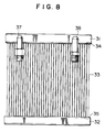
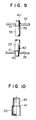
A conventional multi-tube heat exchanger is constructed, for example, as shown in Figs. 8-10. In Fig. 8, a plurality of heat transfer tubes 33 each having a circular cross section are fluidly interconnected between an upper tank 31 and a lower tank 32. Connecting portions between tubes 33 and tanks 31 and 32 are structured, for example, as shown in Figs. 9 and 10. Each end portion of each heat transfer tube 33 is drawn, and a taper portion 41 and a contracted diameter portion 42 are formed. The respective contracted diameter portions 42 are inserted into holes 39 and 40 defined on walls 34 and 35 of upper and lower tanks 31 and 32, and the tanks 31 and 32 are communicated to each other via heat transfer tubes 33 by brazing the inner peripheries of the holes 39 and 40 and the outer surfaces of the contracted diameter portions 42 of the tubes 33.
-
In such a heat exchanger, heat medium (for example, refrigerant) introduced through an inlet pipe 37 is circulated in the heat exchanger and thereafter discharged through an outlet pipe 38. Heat exchange is performed between the refrigerant flowing in heat transfer tubes 33 and air passing through gaps between the tubes 33.
-
In the above-described heat exchanger, insertion of heat transfer tubes 33 into holes 39 and 40 defined on walls 34 and 35 of upper and lower tanks 31 and 32 is facilitated by forming contracted diameter portions 42 on the end portions of each heat transfer tubes 33. Further, although the diameter of each taper portion 41 decreases as it approaches a corresponding contracted diameter portion 42, because the greatest diameter of the taper portion 41 is formed larger than the inner diameter of hole 39 or 40, the length of insertion of each heat transfer tube 33 into upper or lower tank 31 or 32 through hole 39 or 40 is maintained at a predetermined constant length.
-
In such a heat exchanger, however, taper portion 41 and contracted diameter portion 42 are formed on an end portion of each heat transfer tube 33, and the inner diameter of this portion becomes small as compared with that of other portions of the tube 33, as shown in Fig. 10. Therefore, the pressure loss of heat medium (for example, refrigerant) flowing in each heat transfer tube 33 increases at this portion.
-
Generally, the resistance P of a path having a path length"l" and an equivalent diameter (an inner diameter) "d" is represented by the following equation.
Where, "u" is a flow rate, "g" is an acceleration of gravity and "λ" is a coefficient.
-
Further, the relationship between a circulation amount of refrigerant G and a flow rate "u" is represented by the following equation.
Where, A is a cross-sectional area of a path.
-
When the circulation amount of refrigerant G is constant, the path length "l" is defined as an insertion length into a tank and the insertion length is the same for every tube having an arbitrary inner diameter (an inner diamenter: d
n ), from the above-described equations (1) and (2), the resistance P
n of a path defined by a tube diameter d
n and a cross-sectional area A n of the path is represented by the following equation.
-
Next, A
n will be explained. First, arrangement of tubes of a heat exchanger will be explained in reference to Fig. 12. The outer diameter of a tube is indicated by D, an arrangement pitch of tubes in an air-flow direction is indicated by X and an arrangement pitch of tubes in a direction perpendicular to the air-flow direction is indicated by Y. Where, a number of tubes capable of being arranged in a unit area of a tank wall is considered at a condition where X/D and Y/D are constant, respectively, even in a case where the outer diameter of a tube varies. In this case, if the outer diameter of a tube becomes small, the number of tubes N
n capable of being arranged in a unit area increases. Where, the cross-sectional area A
n of the path is calculated by A
n = (1/4) · π · d
n 2 × N
n . This "d
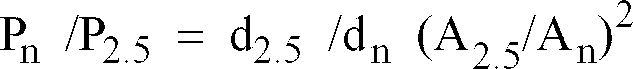
n " is determined at a condition where the thickness of a tube is constant even if the outer diameter of the tube varies. The thickness of a tube can be selected as a constant value in order to obtain a desired corrosion resistance even if the outer diameter of the tube varies. When the relationship between the diameter "d
n " of a tube and the resistance "P
n " of a path is determined as a ratio of the resistance to that at a condition of an inner diameter of 2.5 mm, the ratio of the path resistances is represented by the following equation.
The P n at a condition of P
2.5=1 is shown in Fig. 11.
-
As shown in Fig. 11, as the inner diameter of tube 33 decreases, the ratio of the path resistances at an insertion portion rapidly increases. Therefore, when the thickness of a tube is constant, if the outer diameter of the tube decreases, in a case where diameter contracted portions 42 are formed as described above, the pressure loss in the circuit of the heat exchanger may rapidly increase as well as the performance thereof may rapidly deteriorate. Particularly, this becomes remarkable in a range of an inner diameter of not more than 2 mm.
-
It would be desirable to provide a multi-tube heat exchanger having small-diameter heat transfer tubes which can prevent increase of pressure loss and indicate an excellent heat exchange ability.
-
A multi-tube heat exchanger according to the present invention includes a pair of tanks spaced from each other and a plurality of heat transfer tubes each having a circular cross section and fluidly interconnected between the pair of tanks. Each of the plurality of heat transfer tubes has a first radially expanded portion at a first end portion engaging an outer surface of a wall of a first tank of the pair of tanks.
-
Each heat transfer tube may have a second radially expanded portion at a second end portion engaging an outer surface of a wall of a second tank of the pair of tanks in addition to the first radially expanded portion.
-
The first or the second radially expanded portion may be formed as an annular protruded portion formed on an outer surface of the first or the second end portion. Alternatively, the first or the second radially expanded portion may be formed as a radially expanded taper portion formed on a tip portion of the first or the second end portion. In the latter case, the wall of the first or the second tank may be formed as a burr at a position connected with the first or the second end portion, and the radially expanded taper portion may be fitted onto an outer surface of the burr.
-
The present invention can be appropriately applied to a heat exchanger having heat transfer tubes with an inner diameter of not more than 2 mm.
-
In such a multi-tube heat exchanger, since a diameter contracted portion such as one in a conventional heat exchanger is not formed at an end portion of a heat transfer tube even if a radially expanded portion is formed, increase of pressure loss of a flowing heat medium in the tube can be prevented, particularly, effectively in a small-diameter tube such as one having a diameter of not more than 2 mm. Because the radially expanded portion engages an outer surface of a wall of a tank, the insertion length of the tube end portion into the tank can be precisely regulated, or a structure where the tube end portion is not inserted into the tank can be employed. As a result, a heat exchanger having a desired dimension can be obtained, and the pressure loss in the circuit of the heat exchanger can be further decreased, thereby achieving a high heat exchange performance.
-
When the radially expanded portion is formed as an annular protruded portion formed on an outer surface of the tube end portion, a diameter contracted portion is not formed at all, increase of pressure loss can be effectively prevented. Because the annular protruded portion is engaged to the outer surface of the tank, the insertion length of the tube end portion into the tank is easily and precisely set at a predetermined length.
-
When the radially expanded portion is formed as a radially expanded taper portion formed on a tip portion of the tube end portion and the radially expanded taper portion is fitted onto an outer surface of a burr formed on a tank wall at a position connected with the tube end portion, the tube end portion can be connected to the burr on the tank wall without being projected into the tank and without forming a diameter contracted portion. As a result, the flow in the tank can be smoothened as well as the pressure loss in the tank can be suppressed small, and therefore, increase of pressure loss as the whole of the heat exchanger can be prevented more effectively.
-
Further objects, features, and advantages of the present invention will be understood from the following detailed description of the embodiments of the present invention with reference to the appropriate figures.
-
Some embodiments of the invention will now be described with reference to the appropriate figures, which are given by way of example only, and are not intended to limit the present invention.
-
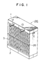
Fig. 1 is a perspective view of a multi-tube heat exchanger according to a first embodiment of the present invention.
-
Fig. 2 is an enlarged, partial, vertical sectional view of the heat exchanger depicted in Fig. 1, showing connecting portions of a heat transfer tube and tank walls.
-
Fig. 3 is an enlarged, partial, vertical sectional view of a connecting portion of an end portion of a heat transfer tube and a tank wall depicted in Fig. 2.
-
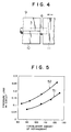
Fig. 4 is a side view of upper and lower dies and a jig for forming an radially expanded portion on a tube end portion of a tube depicted in Fig. 2.
-
Fig. 5 is a graph showing relationships between a pressure loss in a circuit and a circulation amount of refrigerant in the heat exchangers depicted in Figs. 1 and 8.
-
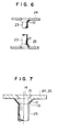
Fig. 6 is a partial, vertical sectional view of connecting portions of a heat transfer tube and tank walls in a heat exchanger according to a second embodiment of the present invention.
-
Fig. 7 is an enlarged, partial, vertical sectional view of a connecting portion of an end portion of a heat transfer tube and a tank wall depicted in Fig. 6.
-
Fig. 8 is an elevational view of a conventional heat exchanger.
-
Fig. 9 is an enlarged, partial, vertical sectional view of the heat exchanger depicted in Fig. 8, showing connecting portions of a heat transfer tube and tank walls.
-
Fig. 10 is an enlarged, partial, vertical sectional view of a connecting portion of an end portion of a heat transfer tube and a tank wall depicted in Fig. 9.
-
Fig. 11 is a graph showing a relationship between an inner diameter of a heat transfer tube and a ratio of path resistances.
-
Fig. 12 is a schematic plan view of arranged heat transfer tubes.
-
Referring to Figs. 1-3, a multi-tube heat exchanger 100 is provided according to a first embodiment of the present invention. Heat exchanger 100 includes a pair of tanks 1 and 2, for example, an upper tank 1 and a lower tank 2. A plurality of heat transfer tubes 3 each having a circular cross section and a small diameter (for example, refrigerant tubes) are fluidly interconnected between tanks 1 and 2. In this embodiment, at least heat transfer tubes 3 are made from an aluminum alloy, and fixed to tanks 1 and 2 by brazing. Inlet pipe 12 and outlet pipe 13 are connected to tank 1. In this embodiment, although a supporting plate 20 is provided at a position corresponding to a middle portion of each heat transfer tube 3 in the axial direction in order to support the tubes 3, this supporting plate 20 may be omitted. Heat exchange medium, for example, refrigerant, is introduced into tank 1 through inlet pipe 12, and after circulation through heat exchanger 100, the heat exchange medium flows out of tank 1 through outlet pipe 13. Heat exchange is performed between the refrigerant flowing in heat transfer tubes 3 and air passing through gaps between the tubes 3.
-
As depicted in Figs. 2 and 3, an annular protruded portion 6 provided as a radially expanded portion is formed at least on a first end portion 3a of heat transfer tube 3, in this embodiment, on each of first and second end portion 3a and 3b. The annular protruded portions 6 engage the outer surfaces of a tank wall 4 of tank 1 and a tank wall 5 of tank 2, respectively. These annular protruded portions 6 are formed on the outer surface of each heat transfer tube 3 at both end portions 3a and 3b. Tube insertion holes 7 and 8 are defined on tank walls 4 and 5, respectively. End portions 3a and 3b of each heat transfer tube 3 are inserted into tube insertion holes 7 and 8, respectively, and are projected into tanks 1 and 2 at predetermined insertion lengths, respectively.
-
Where, although a method for forming annular protruded portion 6 is not particularly restricted, for example, as shown in Fig. 4, the annular protruded portion 6 can be formed by holding a heat transfer tube 3 from both sides by an upper die 9 and a lower die 10 and pressing the tube end portion by a jig 11 in a direction shown by an arrow.
-
In such a multi-tube heat exchanger 100 thus constructed, since annular protruded portion 6 provided as a radially expanded portion is formed on each tube end portion but a diameter contracted portion is not formed as in a conventional heat exchanger, increase of pressure loss at a connecting portion of a heat transfer tube and a tank wall can be prevented. Further, the insertion length of each of tube end portions 3a and 3b is set to a predetermined desired length easily and precisely by engagement of annular protruded portion 6 to the outer surface of each of tank walls 4 and 5. As a result, a multi-tube heat exchanger 100 having a desired dimension and a high heat exchange performance can be realized.
-
Fig. 5 shows a relationship between a pressure loss in a circuit and a circulation amount of refrigerant for comparing the performance of the heat exchanger depicted in Figs. 1-3 with the performance of the conventional heat exchanger depicted in Figs. 8-10.
-
In heat exchanger 100 depicted in Figs. 1-3, each of heat transfer tubes 3 has an inner diameter of 2.4 mm at its tube end portion, and in the heat exchanger depicted in Figs. 8-10, each of heat transfer tubes 33 has an inner diameter of 1.8 mm at its diameter contracted tube end portion. The inner diameter of a tube portion except tube end portions is the same in both of the heat exchanger 100 of this embodiment and the conventional heat exchanger. The heat exchanger 100 of this embodiment indicates a pressure-loss property 51, and the conventional heat exchanger indicates a pressure-loss property 52. Thus, in the present invention, increase of pressure loss can be effectively prevented.
-
Figs. 6 and 7 show a structure of a connecting portion of tube end portions and tank walls in a multi-tube heat exchanger according to a second embodiment of the present invention. In this embodiment, a radially expanded taper portion 12 is formed as a radially expanded portion on each of tip portions of the tube end portions of each heat transfer tube 23. Each heat transfer tubes 23 has an inner diameter of not more than 2 mm and is made from an aluminum alloy. On each of tank walls 24 and 25, a burr 14 is formed at a position connected with each corresponding tube end portion. Burr 14 is formed as a shape along the shape of radially expanded taper portion 12. Radially expanded taper portion 12 is fitted onto an outer surface 15 of burr 14, and an inner surface 13 of the radially expanded taper portion 12 and the outer surface 15 of burr 14 are brazed to each other.
-
In this embodiment, because a diameter contracted portion is not formed on a tube end portion of heat transfer tube 23 as in a conventional heat exchanger, increase of pressure loss at a connecting portion of the tube end portion and a tank wall can be effectively prevented. Further, in this embodiment, because the tube end portion is not inserted into the interior of a tank, the flow in the tank can be smoothened as well as the pressure loss in the tank can be suppressed small, the pressure loss in the whole circuit of the heat exchanger can be suppressed smaller.
-
Although multi-tube heat exchangers arranged with tanks 1 and 2 in a vertical direction have been explained in the above-described embodiments, the arrangement direction of tanks may be in a horizontal or other directions.