US10197337B2 - Heat transfer sheet for rotary regenerative heat exchanger - Google Patents
Heat transfer sheet for rotary regenerative heat exchanger Download PDFInfo
- Publication number
- US10197337B2 US10197337B2 US14/926,920 US201514926920A US10197337B2 US 10197337 B2 US10197337 B2 US 10197337B2 US 201514926920 A US201514926920 A US 201514926920A US 10197337 B2 US10197337 B2 US 10197337B2
- Authority
- US
- United States
- Prior art keywords
- heat transfer
- sheet
- transfer sheet
- undulating surface
- flow
- Prior art date
- Legal status (The legal status is an assumption and is not a legal conclusion. Google has not performed a legal analysis and makes no representation as to the accuracy of the status listed.)
- Active, expires
Links
- 230000001172 regenerating effect Effects 0.000 title claims description 11
- 239000003546 flue gas Substances 0.000 claims description 30
- UGFAIRIUMAVXCW-UHFFFAOYSA-N Carbon monoxide Chemical compound [O+]#[C-] UGFAIRIUMAVXCW-UHFFFAOYSA-N 0.000 claims description 28
- 230000007704 transition Effects 0.000 claims description 3
- 239000007789 gas Substances 0.000 description 11
- 239000004071 soot Substances 0.000 description 8
- 238000004140 cleaning Methods 0.000 description 6
- 239000013529 heat transfer fluid Substances 0.000 description 5
- 238000011084 recovery Methods 0.000 description 5
- 238000002485 combustion reaction Methods 0.000 description 4
- 230000000694 effects Effects 0.000 description 3
- 230000035515 penetration Effects 0.000 description 3
- QAOWNCQODCNURD-UHFFFAOYSA-N Sulfuric acid Chemical compound OS(O)(=O)=O QAOWNCQODCNURD-UHFFFAOYSA-N 0.000 description 2
- 239000012530 fluid Substances 0.000 description 2
- 238000005192 partition Methods 0.000 description 2
- 229910000831 Steel Inorganic materials 0.000 description 1
- NINIDFKCEFEMDL-UHFFFAOYSA-N Sulfur Chemical compound [S] NINIDFKCEFEMDL-UHFFFAOYSA-N 0.000 description 1
- 238000007664 blowing Methods 0.000 description 1
- 150000001875 compounds Chemical class 0.000 description 1
- 238000010276 construction Methods 0.000 description 1
- 239000000446 fuel Substances 0.000 description 1
- 239000000463 material Substances 0.000 description 1
- 238000012986 modification Methods 0.000 description 1
- 230000004048 modification Effects 0.000 description 1
- 239000013618 particulate matter Substances 0.000 description 1
- 230000000750 progressive effect Effects 0.000 description 1
- 230000005855 radiation Effects 0.000 description 1
- 125000006850 spacer group Chemical group 0.000 description 1
- 239000010959 steel Substances 0.000 description 1
- 229910052717 sulfur Inorganic materials 0.000 description 1
- 239000011593 sulfur Substances 0.000 description 1
Images


Classifications
-
- F—MECHANICAL ENGINEERING; LIGHTING; HEATING; WEAPONS; BLASTING
- F28—HEAT EXCHANGE IN GENERAL
- F28D—HEAT-EXCHANGE APPARATUS, NOT PROVIDED FOR IN ANOTHER SUBCLASS, IN WHICH THE HEAT-EXCHANGE MEDIA DO NOT COME INTO DIRECT CONTACT
- F28D19/00—Regenerative heat-exchange apparatus in which the intermediate heat-transfer medium or body is moved successively into contact with each heat-exchange medium
- F28D19/04—Regenerative heat-exchange apparatus in which the intermediate heat-transfer medium or body is moved successively into contact with each heat-exchange medium using rigid bodies, e.g. mounted on a movable carrier
- F28D19/041—Regenerative heat-exchange apparatus in which the intermediate heat-transfer medium or body is moved successively into contact with each heat-exchange medium using rigid bodies, e.g. mounted on a movable carrier with axial flow through the intermediate heat-transfer medium
- F28D19/042—Rotors; Assemblies of heat absorbing masses
- F28D19/044—Rotors; Assemblies of heat absorbing masses shaped in sector form, e.g. with baskets
-
- F—MECHANICAL ENGINEERING; LIGHTING; HEATING; WEAPONS; BLASTING
- F24—HEATING; RANGES; VENTILATING
- F24H—FLUID HEATERS, e.g. WATER OR AIR HEATERS, HAVING HEAT-GENERATING MEANS, e.g. HEAT PUMPS, IN GENERAL
- F24H7/00—Storage heaters, i.e. heaters in which the energy is stored as heat in masses for subsequent release
- F24H7/02—Storage heaters, i.e. heaters in which the energy is stored as heat in masses for subsequent release the released heat being conveyed to a transfer fluid
-
- F—MECHANICAL ENGINEERING; LIGHTING; HEATING; WEAPONS; BLASTING
- F28—HEAT EXCHANGE IN GENERAL
- F28D—HEAT-EXCHANGE APPARATUS, NOT PROVIDED FOR IN ANOTHER SUBCLASS, IN WHICH THE HEAT-EXCHANGE MEDIA DO NOT COME INTO DIRECT CONTACT
- F28D11/00—Heat-exchange apparatus employing moving conduits
- F28D11/02—Heat-exchange apparatus employing moving conduits the movement being rotary, e.g. performed by a drum or roller
-
- F—MECHANICAL ENGINEERING; LIGHTING; HEATING; WEAPONS; BLASTING
- F28—HEAT EXCHANGE IN GENERAL
- F28D—HEAT-EXCHANGE APPARATUS, NOT PROVIDED FOR IN ANOTHER SUBCLASS, IN WHICH THE HEAT-EXCHANGE MEDIA DO NOT COME INTO DIRECT CONTACT
- F28D19/00—Regenerative heat-exchange apparatus in which the intermediate heat-transfer medium or body is moved successively into contact with each heat-exchange medium
-
- F—MECHANICAL ENGINEERING; LIGHTING; HEATING; WEAPONS; BLASTING
- F28—HEAT EXCHANGE IN GENERAL
- F28F—DETAILS OF HEAT-EXCHANGE AND HEAT-TRANSFER APPARATUS, OF GENERAL APPLICATION
- F28F3/00—Plate-like or laminated elements; Assemblies of plate-like or laminated elements
- F28F3/02—Elements or assemblies thereof with means for increasing heat-transfer area, e.g. with fins, with recesses, with corrugations
- F28F3/025—Elements or assemblies thereof with means for increasing heat-transfer area, e.g. with fins, with recesses, with corrugations the means being corrugated, plate-like elements
Definitions
- the devices described herein relate to heat transfer sheets of the type found in rotary regenerative heat exchangers.
- Rotary regenerative heat exchangers are commonly used to recover heat from flue gases exiting a furnace, steam generator or flue gas treatment equipment.
- Conventional rotary regenerative heat exchangers have a rotor mounted in a housing that defines a flue gas inlet duct and a flue gas outlet duct for the flow of heated flue gases through the heat exchanger.
- the housing further defines another set of inlet ducts and outlet ducts for the flow of gas streams that receive the recovered heat energy.
- the rotor has radial partitions or diaphragms defining compartments therebetween for supporting baskets or frames to hold heat transfer sheets.
- the heat transfer sheets are stacked in the baskets or frames. Typically, a plurality of sheets are stacked in each basket or frame. The sheets are closely stacked in spaced relationship within the basket or frame to define passageways between the sheets for the flow of gases. Examples of heat transfer element sheets are provided U.S. Pat. Nos. 2,596,642; 2,940,736; 4,363,222; 4,396,058; 4,744,410; 4,553,458; 6,019,160; and 5,836,379.
- Hot gas is directed through the heat exchanger to transfer heat to the sheets.
- the recovery gas stream air side flow
- the recovery gas stream consists of combustion air that is heated and supplied to a furnace or steam generator.
- the recovery gas stream shall be referred to as combustion air or air.
- the sheets are stationary and the flue gas and the recovery gas ducts are rotated.
- a heat transfer sheet having utility in rotary regenerative heat exchangers is described. Gas flow is accommodated across the heat transfer sheet from a leading edge to a trailing edge.
- the heat transfer sheet is defined in part by a plurality of sheet spacing features such as ribs (also known as “notches”) or flat portions extending substantially parallel to the direction of the flow of a heat transfer fluid such as air or flue gas.
- the sheet spacing features form spacers between adjacent heat transfer sheets.
- the heat transfer sheet also includes undulating surfaces extending between adjacent sheet spacing features, with each undulating surface being defined by lobes (also known as “undulations” or “corrugations”).
- the lobes of the different undulating surfaces extend at an angle A u relative to the sheet spacing features, the angle A u being different for at least a portion of the undulating surfaces, thereby providing different surface geometries on the same heat transfer sheet.
- the angle A u may also change for each of the lobes to provide a continuously varying surface geometry.
- FIG. 1 is a partially cut-away perspective view of a prior art rotary regenerative heat exchanger.
- FIG. 2 is a top plan view of a basket including three prior art heat transfer sheets.
- FIG. 3 is a perspective view of a portion of three prior art heat transfer sheets shown in a stacked configuration.
- FIG. 4 is a side elevational view of a prior art heat transfer sheet.
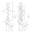
- FIG. 5 is a side elevational view of a heat transfer sheet according to one embodiment of the present invention having two different surface geometries on the same sheet.
- FIG. 6 is a cross-sectional elevation view of a portion of the heat transfer sheet, as taken at section VI-VI of FIG. 5 .
- FIG. 7 is a cross-sectional elevation view of a portion of the heat transfer sheet, as taken at section VII-VII of FIG. 5 .
- FIG. 8 is a side elevational view of an embodiment of a heat transfer sheet showing another arrangement of two different surface geometries on the same sheet.
- FIG. 9 is a side elevational view of another heat transfer sheet showing three or more different surface geometries on the same sheet.
- FIG. 10 is a side elevational view of yet another embodiment of a heat transfer sheet showing a surface geometry that varies continuously over the length of the sheet.
- FIG. 11 is a cross-sectional elevation view of a portion of another embodiment of three heat transfer sheets according to the present invention in stacked relationship.
- FIG. 12 is a cross-sectional elevation view of a portion of another embodiment of three heat transfer sheets in stacked relationship.
- FIG. 13 is a side elevational view of a heat transfer sheet according to one embodiment of the present invention having two different surface geometries on the same sheet.
- FIG. 14 illustrates portions of the heat transfer sheets of FIGS. 6 and 7 in a side by side format.
- a rotary regenerative heat exchanger generally designated by the reference number 10 , has a rotor 12 mounted in a housing 14 .
- the housing 14 defines a flue gas inlet duct 20 and a flue gas outlet duct 22 for accommodating the flow of a heated flue gas stream 36 through the heat exchanger 10 .
- the housing 14 further defines an air inlet duct 24 and an air outlet duct 26 to accommodate the flow of combustion air 38 through the heat exchanger 10 .
- the rotor 12 has radial partitions 16 or diaphragms defining compartments 17 therebetween for supporting baskets (frames) 40 of heat transfer sheets (also known as “heat transfer elements”).
- the heat exchanger 10 is divided into an air sector and a flue gas sector by sector plates 28 , which extend across the housing 14 adjacent the upper and lower faces of the rotor 12 . While FIG. 1 depicts a single air stream 38 , multiple air streams may be accommodated, such as tri-sector and quad-sector configurations. These provide multiple preheated air streams that may be directed for different uses.
- a sheet basket 40 (hereinafter “basket 40 ” includes a frame 41 into which heat transfer sheets 42 are stacked. While only a limited number of heat transfer sheets 42 are shown, it will be appreciated that the basket 40 will typically be filled with heat transfer sheets 42 . As also seen in FIG. 2 , the heat transfer sheets 42 are closely stacked in spaced relationship within the basket 40 to form passageways 44 between adjacent heat transfer sheets 42 . During operation, air or flue gas flows through the passageways 44 .
- the heated flue gas stream 36 is directed through the gas sector of the heat exchanger 10 and transfers heat to the heat transfer sheets 42 .
- the heat transfer sheets 42 are then rotated about axis 18 to the air sector of the heat exchanger 10 , where the combustion air 38 is directed over the heat transfer sheets 42 and is thereby heated.
- heat transfer sheets 42 are shown in a stacked relationship.
- heat transfer sheets 42 are steel planar members that have been shaped to include one or more ribs 50 (also known as “notches”) and undulating surfaces 52 defined in part by undulation peaks 53 .
- the undulation peaks 53 extend upward and downward in an alternating fashion (also known as “corrugations”).
- the heat transfer sheets 42 also include a plurality of larger ribs 50 each having rib peaks 51 that are positioned at generally equally spaced intervals and operate to maintain spacing between adjacent heat transfer sheets 42 when stacked adjacent to one another and cooperate to form sides of passageways ( 44 of FIG. 2 ). These accommodate the flow of air or flue gas between the heat transfer sheets 42 .
- the undulation peaks 53 defining the undulating surfaces 52 in the prior art heat transfer sheet 42 are of all the same height.
- the ribs 50 extend at a predetermined angle (e.g. 0 degrees) relative to the flow of air or flue gas through the rotor ( 12 of FIG. 1 ).
- the undulation peaks 53 defining the undulating surfaces 52 in the prior art are arranged at the same angle A u relative to the ribs and, thus, the same angle relative to the flow of air or flue gas indicated by the arrows marked “Air Flow”.
- the undulating surfaces 52 act, among other things, to increase turbulence in the air or flue gas flowing through the passageways ( 44 of FIG. 2 ) and thereby disrupt the thermal boundary layer at the surface of the heat transfer sheet 42 . In this manner, the undulating surfaces 52 improve heat transfer between the heat transfer sheet 42 and the air or flue gas.
- a novel heat transfer sheet 60 has a length L substantially parallel to a direction of heat transfer fluid (hereinafter “air or flue gas”) flow and extending from a leading edge 80 to a trailing edge 90 .
- air or flue gas heat transfer fluid
- leading edge and trailing edge are used herein for convenience. They relate to the flow of hot air across the sheet 60 indicated by the arrows and labeled “Air Flow”.
- the heat transfer sheet 60 may be used in place of conventional heat transfer sheets 42 in a rotary regenerative heat exchanger.
- heat transfer sheets 60 may be stacked and inserted in a basket 40 for use in a rotary regenerative heat exchanger.
- the heat transfer sheet 60 includes sheet spacing features 59 formed thereon, which effect the desired spacing between sheets 60 and form flow passages 61 between the adjacent heat transfer sheets 60 when the sheets 60 are stacked in the basket 40 ( FIG. 2 ).
- the sheet spacing features 59 extend in spaced relationship substantially along the length of the heat transfer sheet (L of FIG. 5 ) and substantially parallel to the direction of the flow of air or flue gas through the rotor of the heat exchanger.
- Each flow passage 61 extends along the entire length L of the sheet 60 , from the leading edge 80 to the trailing edge 90 , between adjacent ribs 62 .
- the sheet spacing features 59 are shown as ribs 62 .
- Each rib 62 is defined by a first lobe 64 and a second lobe 64 ′.
- the first lobe 64 defines a peak (apex) 66 that is directed outwardly from a peak 66 ′ defined by the second lobe 64 ′ in a generally opposite direction.
- the peaks 66 , 66 ′ of the ribs 62 engage the adjacent heat transfer sheets 60 to maintain the spacing between adjacent heat transfer sheets.
- the heat transfer sheets 60 may be arranged such that the ribs 62 on one heat transfer sheet are located about mid-way between the ribs 62 on the adjacent heat transfer sheets for support. As shown in FIG. 5 , the flow passages 61 define a straight portion that extends the entire length L between a first end and a second end. The straight portion is positioned over the undulating surfaces 68 .
- the sheet spacing features 59 may be of other shapes to effect the desired spacing between sheets 60 and form flow passages 61 between the adjacent heat transfer sheets 60 .
- the heat transfer sheet 60 may include sheet spacing features 59 in the form of longitudinally extending flat regions 88 that are substantially parallel to, and spaced equally with, ribs 62 of an adjacent heat transfer sheet, upon which the ribs 62 of the adjacent heat transfer sheet rest.
- the flat regions 88 extend substantially along the entire length L of the heat transfer sheet 60 .
- the sheet 60 may include alternating ribs 62 and flat regions 88 , which rest on the alternating ribs 62 and flat regions 88 of an adjacent sheet 60 .
- one heat transfer sheet 60 may include all longitudinally extending flat regions 88 , with the other heat transfer sheet 60 includes all ribs 62 .
- each undulating surface 68 extends substantially parallel to the other undulating surfaces 68 between the sheet spacing features 59 .
- each undulating surface 68 is defined by lobes (undulations or corrugations) 72 , 72 ′.
- Each lobe 72 , 72 ′ defines in part a U-shaped channel having respective peaks 74 , 74 ′, and each lobe 72 , 72 ′ extends along the heat transfer sheet 60 in a direction defined along the ridges of its peaks 74 , 74 ′ as shown in FIG. 5 .
- Each of the undulating surfaces 68 has a peak-to-peak height H u1 .
- the undulating surfaces 68 are in the flow passage 61 .
- each undulating surface 70 extends substantially parallel to the other undulating surfaces 70 between the sheet spacing features 59 .
- Each undulating surface 70 includes one lobe (undulation or corrugation) 76 projecting in an opposite direction from another lobe (undulation or corrugation) 76 ′.
- Each lobe 76 , 76 ′ defines in part a channel 61 having respective peaks 78 , 78 ′, and each lobe 76 , 76 ′ extends along the heat transfer sheet 60 in a direction defined along the ridges of its peaks 74 , 74 ′ as shown in FIG. 6 .
- Each of the undulating surfaces 70 has a peak-to-peak height of H u2 .
- the lobes 72 , 72 ′ of undulating surfaces 68 extend at different angles than the lobes 76 , 76 ′ of undulating surfaces 70 , with respect to the sheet spacing features 59 , as indicated by angles A u1 and A u2 , respectively.
- the sheet spacing features 59 are generally parallel to the main flow direction of the air or flue gas across the heat transfer sheet 60 .
- the channels of the undulating surfaces 68 extend substantially parallel to the direction of the sheet spacing features 59
- the channels of the undulating surfaces 70 are angled in the same direction as undulation peaks 78 .
- a u1 is zero degrees
- a u2 in this embodiment is approximately 45 degrees.
- the undulating surfaces 52 in conventional heat transfer sheets 42 all extend at the same angle, A u , relative to the adjacent sheet spacing features 59 .
- angles described here are only for illustrative purposes. It is to be understood that the invention encompasses a wide variety of angles.
- the length L 1 of the undulating surfaces 68 of FIG. 5 (and FIG. 8 ) may be selected based on factors such as heat transfer fluid flow, desired heat transfer, location of the zone where sulfuric acid, condensable compounds, and particulate matter collect on the heat transfer surface, and desired sootblower penetration for cleaning.
- Soot blowers have been used to clean heat transfer sheets. These deliver a blast of high-pressure air or steam through the passages ( 44 of FIG. 2, 61 of FIGS. 6, 7, 11, 12 ) between the stacked elements to dislodge particulate deposits from the surface of heat transfer sheets.
- L 1 may be a distance such that all or a portion of the deposit is located on the section of the heat transfer sheet that is substantially parallel to the direction of the flow of air or flue gas through the rotor of the heat exchanger ( 36 , 38 of FIG. 1 ).
- L 1 may be less than one-third of the entire length L of the heat transfer sheet 60 , and more preferably less than one-fourth of the entire length L of the heat transfer sheet 60 .
- This provides a sufficient amount of undulating surface 70 to develop turbulent flow of the heat transfer fluid and so that the turbulent flow continues across the undulating surface 70 .
- Undulating surface 70 is constructed to be sufficiently rigid to withstand the full range of operating conditions, including cleaning with a sootblower jet, for the heat transfer sheet 60 .
- the longer L 1 (and Li, L 3 ) should be for optimum performance. Also, the lower the gas outlet temperature from the air preheater, the longer L 1 (and L 2 , L 3 ) should be for optimum performance.
- H u1 and H u2 may be equal.
- H u1 and H u2 may differ.
- H u1 is less than H u2 (see FIG. 14 )
- both H u1 and H u2 are less than HL.
- the undulating surfaces 52 in conventional heat transfer sheets 42 are all of the same height.
- FIG. 5 allows for maintaining higher velocity and kinetic energy of the sootblower jet to a deeper location within flow passage ( 61 of FIGS. 6 and 7 ), which is expected to lead to better cleaning.
- FIG. 5 is believed to allow for better cleaning by a soot blower jet, or potentially cleaning a stickier deposit on the heat transfer surface since the undulating surfaces 68 are better aligned with a jet directed towards the leading edge 80 , thus allowing for greater penetration of the soot blower jet along the flow passages ( 61 of FIGS. 6, 7 ).
- the heat transfer sheet as described herein becomes more compatible with an infrared radiation (hot spot) detector.
- FIG. 5 proved to have low susceptibility to flutter during soot blowing tests.
- fluttering of the heat transfer sheets is undesirable as it causes excessive deformation of the sheets, plus it causes them to wear against each other and, thereby, reduce the useful life of the sheets.
- the undulating surfaces 68 are substantially aligned with the direction of the soot blower jet (Air Flow), the velocity and kinetic energy of the sootblower jet is preserved to a greater depth along the flow channel ( 61 of FIGS. 6 and 7 ). This results in more energy being available for removal of the deposit on the heat transfer surface.
- FIG. 8 shows another embodiment of a heat transfer sheet 160 that incorporates three surface geometries.
- heat transfer sheet 160 has a series of sheet spacing features 59 at spaced intervals that extend longitudinally and substantially parallel to the direction of the flow of the air or flue gas through the rotor of a heat exchanger.
- Heat transfer sheet 160 also includes undulating surfaces 68 and 70 , with undulating surfaces 68 being located on both a leading edge 80 and a trailing edge 90 of the heat transfer sheet 160 .
- the lobes 72 of undulating surfaces 68 extend in the first direction represented by angle A u1 relative to the sheet spacing features 59 .
- a u1 is zero since sheet spacing features 59 is parallel to lobes 72 .
- Lobes 76 of undulating surfaces 70 extend in the second direction A u2 relative to the sheet spacing features 59 .
- the present invention is not limited in this regard, however, as the undulating surfaces 68 at the trailing edge 90 of the sheet 60 may be angled differently from the undulating surfaces 68 at the leading edge 80 .
- the heights of the undulating surfaces 68 may also be varied relative to the heights of the undulating surfaces 70 .
- a sum of the length L 3 of the undulating surfaces 68 at the trailing edge 90 and the length L 2 of the undulating surfaces 68 at the leading edge 80 is less than one-half of the length L of the heat transfer sheet 60 .
- it is less than one-third of the entire L of the heat transfer sheet 60 .
- the heat transfer sheet 160 of FIG. 8 may be used, for example, where soot blowers are directed at both the leading and trailing edges 80 and 90 .
- the heat transfer sheet of the present invention may include any number of different surface geometries along the length of each flow passage 61 .
- FIG. 9 depicts a heat transfer sheet 260 that incorporates three different surface geometries.
- heat transfer sheet 260 includes sheet spacing features 59 at spaced intervals which extend longitudinally and parallel to the direction of the flow of air or flue gas through the rotor of a heat exchanger and defining flow passages 61 between adjacent sheets 260 .
- Heat transfer sheet 260 also includes undulating surfaces 68 , 70 and 71 with undulating surfaces 68 being located on a leading edge 80 .
- the lobes 72 of undulating surfaces 68 extend in a first direction represented by angle A u1 (parallel to the sheet spacing features 59 , as is shown, for example).
- the lobes 76 of undulating surfaces 70 extend across the heat transfer sheet 260 in a second direction at angle A u2 relative to the sheet spacing features 59
- the lobes 73 of undulating surfaces 71 extend across the heat transfer sheet 260 in a third direction at angle A u3 relative to the sheet spacing features 59 , which is different from A u2 and A u1 .
- a u3 maybe the negative (reflected) angle of A u2 relative to the sheet spacing features 59 .
- the heights H u1 and H u2 of undulating surfaces 68 , 70 , and 71 may be varied.
- undulating surfaces 70 and 71 alternate along the heat transfer sheet 260 , thereby providing for increased turbulence of the heat transfer fluid as it flows.
- the turbulence comes in contact with the heat transfer sheets 260 for a longer period of time and thus enhances heat transfer.
- the swirl flow also serves to mix the flowing fluid and provides a more uniform flow temperature.
- This turbulence is believed to enhance the heat transfer rate of the heat transfer sheets 60 with a minimal increase in pressure drop, while causing a significant increase in the amount of total heat transferred.
- a heat transfer sheet 360 incorporates a continuously varying surface geometry along a plurality of lobes 376 .
- heat transfer sheet 360 includes sheet spacing features 59 at spaced intervals which extend longitudinally and substantially parallel to the direction of the flow of the air or flue gas through the rotor of a heat exchanger and defining flow passages such as flow passages 61 of FIGS. 6 and 7 , between adjacent sheets 360 .
- Flow passages are created between the sheet spacing features 59 under lobes 376 of the undulating surface 368 .
- the lobes 376 become increasingly angled with respect to the sheet spacing features 59 over the length L of the sheet 360 from the leading edge 80 to the trailing edge 90 .
- This construction allows a soot blower jet to penetrate from the leading edge 80 a greater distance into the flow passages as compared with prior art designs.
- This design also exhibits greater heat transfer and fluid turbulence near the trailing edge 90 .
- the progressive angling of the undulating surfaces 368 avoids the need for a sharp transition to undulating surfaces of a different angle, while still permitting the undulating surfaces to be somewhat aligned with a soot blower jet to effect deeper jet penetration and better cleaning.
- the heights of the undulating surfaces 368 may also be varied along the length L of the heat transfer sheet 360 .
- FIG. 11 shows an alternative embodiment in which parts with the same numbers have the same function as those described in FIGS. 6 and 7 .
- flat portions 88 meet up with peaks 66 and 66 ′ creating a more effective seal between flow passages 61 on the left and right sides of each sheet spacing feature.
- Flow passages are referred to as a ‘closed channel’.
- FIG. 12 shows another alternative embodiment of the present invention in which parts with the same numbers have the same function as those described in the previous figures. This embodiment differs from FIG. 11 in that sheet spacing features 59 are only included on the center heat transfer sheet.
- FIG. 13 is a top plan view of a heat transfer sheet showing another arrangement of two different surface geometries on the same sheet. Parts with the same reference numbers as that of the previous figures perform the same function.
- This embodiment is similar to that of FIG. 5 .
- adjacent undulation surfaces 70 , 79 have peaks 78 , 81 that are angled in opposite directions with respect to sheet spacing features 59 .
- Undulation peaks 78 make an angle A u2 with respect to sheet spacing features 59 .
- Undulation peaks 81 make an angle A u4 with respect to sheet spacing features 59 .
- FIG. 13 is used for purposes of illustration, however, it should be noted that the invention covers many other embodiments that have adjacent undulated sections parallel lobes each oriented with the angles of their lobes aligned opposite each other.
Landscapes
- Engineering & Computer Science (AREA)
- Physics & Mathematics (AREA)
- Thermal Sciences (AREA)
- Mechanical Engineering (AREA)
- General Engineering & Computer Science (AREA)
- Chemical & Material Sciences (AREA)
- Combustion & Propulsion (AREA)
- Heat-Exchange Devices With Radiators And Conduit Assemblies (AREA)
- Air Supply (AREA)
Abstract
Description
Claims (5)
Priority Applications (2)
| Application Number | Priority Date | Filing Date | Title |
|---|---|---|---|
| US14/926,920 US10197337B2 (en) | 2009-05-08 | 2015-10-29 | Heat transfer sheet for rotary regenerative heat exchanger |
| US16/251,915 US10982908B2 (en) | 2009-05-08 | 2019-01-18 | Heat transfer sheet for rotary regenerative heat exchanger |
Applications Claiming Priority (2)
| Application Number | Priority Date | Filing Date | Title |
|---|---|---|---|
| US12/437,914 US9557119B2 (en) | 2009-05-08 | 2009-05-08 | Heat transfer sheet for rotary regenerative heat exchanger |
| US14/926,920 US10197337B2 (en) | 2009-05-08 | 2015-10-29 | Heat transfer sheet for rotary regenerative heat exchanger |
Related Parent Applications (1)
| Application Number | Title | Priority Date | Filing Date |
|---|---|---|---|
| US12/437,914 Continuation US9557119B2 (en) | 2009-05-08 | 2009-05-08 | Heat transfer sheet for rotary regenerative heat exchanger |
Related Child Applications (1)
| Application Number | Title | Priority Date | Filing Date |
|---|---|---|---|
| US16/251,915 Continuation US10982908B2 (en) | 2009-05-08 | 2019-01-18 | Heat transfer sheet for rotary regenerative heat exchanger |
Publications (2)
| Publication Number | Publication Date |
|---|---|
| US20160153726A1 US20160153726A1 (en) | 2016-06-02 |
| US10197337B2 true US10197337B2 (en) | 2019-02-05 |
Family
ID=42235419
Family Applications (3)
| Application Number | Title | Priority Date | Filing Date |
|---|---|---|---|
| US12/437,914 Expired - Fee Related US9557119B2 (en) | 2009-05-08 | 2009-05-08 | Heat transfer sheet for rotary regenerative heat exchanger |
| US14/926,920 Active 2029-08-04 US10197337B2 (en) | 2009-05-08 | 2015-10-29 | Heat transfer sheet for rotary regenerative heat exchanger |
| US16/251,915 Expired - Fee Related US10982908B2 (en) | 2009-05-08 | 2019-01-18 | Heat transfer sheet for rotary regenerative heat exchanger |
Family Applications Before (1)
| Application Number | Title | Priority Date | Filing Date |
|---|---|---|---|
| US12/437,914 Expired - Fee Related US9557119B2 (en) | 2009-05-08 | 2009-05-08 | Heat transfer sheet for rotary regenerative heat exchanger |
Family Applications After (1)
| Application Number | Title | Priority Date | Filing Date |
|---|---|---|---|
| US16/251,915 Expired - Fee Related US10982908B2 (en) | 2009-05-08 | 2019-01-18 | Heat transfer sheet for rotary regenerative heat exchanger |
Country Status (17)
| Country | Link |
|---|---|
| US (3) | US9557119B2 (en) |
| EP (2) | EP2667138B1 (en) |
| JP (2) | JP5656979B2 (en) |
| KR (2) | KR101316776B1 (en) |
| CN (2) | CN103994688B (en) |
| AU (2) | AU2010245218A1 (en) |
| BR (1) | BRPI1014805A8 (en) |
| CA (2) | CA2830686C (en) |
| DK (2) | DK2667138T3 (en) |
| ES (2) | ES2470670T3 (en) |
| IL (2) | IL215250A (en) |
| MX (1) | MX339981B (en) |
| PL (1) | PL2427712T3 (en) |
| SG (2) | SG185973A1 (en) |
| TW (2) | TWI548856B (en) |
| WO (1) | WO2010129092A1 (en) |
| ZA (2) | ZA201107086B (en) |
Cited By (1)
| Publication number | Priority date | Publication date | Assignee | Title |
|---|---|---|---|---|
| US11340025B2 (en) * | 2017-12-04 | 2022-05-24 | SWISS ROTORS Spolka z o.o. | Heat transmission roll for a rotary cylindrical heat exchanger |
Families Citing this family (17)
| Publication number | Priority date | Publication date | Assignee | Title |
|---|---|---|---|---|
| DE102006003317B4 (en) | 2006-01-23 | 2008-10-02 | Alstom Technology Ltd. | Tube bundle heat exchanger |
| US9557119B2 (en) | 2009-05-08 | 2017-01-31 | Arvos Inc. | Heat transfer sheet for rotary regenerative heat exchanger |
| US9644899B2 (en) * | 2011-06-01 | 2017-05-09 | Arvos, Inc. | Heating element undulation patterns |
| US9200853B2 (en) * | 2012-08-23 | 2015-12-01 | Arvos Technology Limited | Heat transfer assembly for rotary regenerative preheater |
| TWI496918B (en) * | 2013-02-05 | 2015-08-21 | Adpv Technology Ltd Intetrust | Gas release device for coating process |
| ES2707871T3 (en) * | 2013-09-19 | 2019-04-05 | Howden Uk Ltd | Heat exchange element profile with improved cleaning capacity characteristics |
| US10175006B2 (en) | 2013-11-25 | 2019-01-08 | Arvos Ljungstrom Llc | Heat transfer elements for a closed channel rotary regenerative air preheater |
| JP6280989B2 (en) | 2013-12-10 | 2018-02-14 | ホーデン トマセン コンプレッサーズ ビーブイ | Single seal ring stuffing box |
| EP2908080A1 (en) * | 2014-02-13 | 2015-08-19 | Ekocoil Oy | Heat exchanger structure for reducing accumulation of liquid and freezing |
| US10094626B2 (en) | 2015-10-07 | 2018-10-09 | Arvos Ljungstrom Llc | Alternating notch configuration for spacing heat transfer sheets |
| SE541591C2 (en) * | 2016-02-24 | 2019-11-12 | Alfa Laval Corp Ab | A heat exchanger plate for a plate heat exchanger, and a plate heat exchanger |
| DE102016205353A1 (en) * | 2016-03-31 | 2017-10-05 | Mahle International Gmbh | The stacked-plate heat exchanger |
| US10267517B2 (en) * | 2016-07-08 | 2019-04-23 | Arvos Ljungstrom Llc | Method and system for improving boiler effectiveness |
| TWI707121B (en) * | 2016-10-11 | 2020-10-11 | 美商傲華公司 | An alternating notch configuration for spacing heat transfer sheets |
| US10578367B2 (en) | 2016-11-28 | 2020-03-03 | Carrier Corporation | Plate heat exchanger with alternating symmetrical and asymmetrical plates |
| WO2018125134A1 (en) * | 2016-12-29 | 2018-07-05 | Arvos, Ljungstrom Llc. | A heat transfer sheet assembly with an intermediate spacing feature |
| US10837714B2 (en) * | 2017-06-29 | 2020-11-17 | Howden Uk Limited | Heat transfer elements for rotary heat exchangers |
Citations (189)
| Publication number | Priority date | Publication date | Assignee | Title |
|---|---|---|---|---|
| US682607A (en) | 1899-11-22 | 1901-09-17 | Joseph Eck | Roller for calendering-machines. |
| US1429149A (en) | 1920-10-18 | 1922-09-12 | Engineering Dev Company | Heat interchanger |
| GB177780A (en) | 1921-04-01 | 1923-02-15 | Armin Renyi | Improvements in rolling mills for manufacturing corrugated pasteboard, sheet metal and the like |
| US1450351A (en) | 1922-04-22 | 1923-04-03 | Beran Albert | Rolling mill for manufacturing corrugated pasteboard, sheet metal, and the like |
| US1477209A (en) | 1919-05-05 | 1923-12-11 | George Henry De Vore | Radiator for automobiles |
| US1524280A (en) | 1920-11-09 | 1925-01-27 | Ingersoll Rand Co | Condenser tube terminal |
| US1875188A (en) | 1932-01-27 | 1932-08-30 | Sherman Products Corp | Unit formed of sheet material |
| US1894956A (en) | 1929-01-16 | 1933-01-24 | Babcock & Wilcox Co | Air heater |
| US1915742A (en) | 1930-11-28 | 1933-06-27 | Manuf Generale Metallurg Sa | Heat exchange apparatus |
| FR775271A (en) | 1934-05-25 | 1934-12-22 | Cooling radiator for heat engine of motor cars or other similar applications | |
| US1987798A (en) | 1931-05-19 | 1935-01-15 | Ruppricht Siegfried | Thermal insulating material |
| US2023965A (en) | 1930-05-21 | 1935-12-10 | Ljungstroms Angturbin Ab | Heat transfer |
| US2042017A (en) | 1934-08-24 | 1936-05-26 | Orchard Paper Co | Decorative corrugated paper |
| US2102936A (en) | 1937-03-09 | 1937-12-21 | David C Bailey | Window glass guide |
| US2160677A (en) | 1937-09-15 | 1939-05-30 | Hippolyte W Romanoff | Reinforced corrugated sheet |
| US2313081A (en) | 1937-02-02 | 1943-03-09 | Jarvis C Marble | Heat exchange |
| US2432198A (en) | 1945-01-12 | 1947-12-09 | Air Preheater | Heat exchange surface for air preheaters |
| US2438851A (en) | 1943-11-01 | 1948-03-30 | Air Preheater | Plate arrangement for preheaters |
| US2596642A (en) | 1945-05-28 | 1952-05-13 | Jarvis C Marble | Heat exchanger |
| US2782009A (en) | 1952-03-14 | 1957-02-19 | Gen Motors Corp | Heat exchangers |
| US2796157A (en) | 1956-05-18 | 1957-06-18 | Charles R Ginsburg | Structural panel construction |
| FR1219505A (en) | 1958-03-25 | 1960-05-18 | Zd Y V I | Elastic connection of heat exchanger tubes to the heat exchanger base |
| US2940736A (en) | 1949-05-25 | 1960-06-14 | Svenska Rotor Maskiner Ab | Element set for heat exchangers |
| US2983486A (en) | 1958-09-15 | 1961-05-09 | Air Preheater | Element arrangement for a regenerative heat exchanger |
| US3019160A (en) | 1959-05-11 | 1962-01-30 | Diamond Alkali Co | Haloglycoluril bactericidal compositions for disinfecting and bleaching |
| US3111982A (en) | 1958-05-24 | 1963-11-26 | Gutehoffnungshuette Sterkrade | Corrugated heat exchange structures |
| US3158527A (en) | 1960-06-10 | 1964-11-24 | Crown Zellerbach Corp | Plaited structure and method of forming same |
| US3183963A (en) | 1963-01-31 | 1965-05-18 | Gen Motors Corp | Matrix for regenerative heat exchangers |
| GB992413A (en) | 1961-05-25 | 1965-05-19 | Howden James & Co Ltd | Improvements relating to rotary regenerative air preheaters for boiler plant |
| US3216494A (en) | 1960-07-20 | 1965-11-09 | Apv Co Ltd | Heat exchanger plate |
| US3240266A (en) | 1962-03-13 | 1966-03-15 | Atomic Energy Authority Uk | Heat exchangers |
| US3260511A (en) | 1962-07-20 | 1966-07-12 | Ici Ltd | Water cooling towers |
| US3262490A (en) | 1954-04-21 | 1966-07-26 | Chrysler Corp | Process for joining metallic surfaces and products made thereby |
| US3317222A (en) | 1964-04-16 | 1967-05-02 | Cons Edison Co New York Inc | Insert constructions for tubes of heat exchangers and condensers |
| US3372743A (en) | 1967-01-25 | 1968-03-12 | Pall Corp | Heat exchanger |
| US3373798A (en) | 1965-11-19 | 1968-03-19 | Gen Motors Corp | Regenerator matrix |
| US3415502A (en) | 1964-03-24 | 1968-12-10 | Munters Carl Georg | Liquid and gas contact body |
| US3452814A (en) | 1967-02-24 | 1969-07-01 | Gen Electric | Bell-end condenser tubes |
| US3490523A (en) | 1968-04-08 | 1970-01-20 | Us Health Education & Welfare | Transfer device |
| US3523058A (en) | 1968-04-05 | 1970-08-04 | Owens Illinois Inc | Fabricatable stiff-when-wet corrugated paperboard |
| US3532157A (en) | 1969-01-03 | 1970-10-06 | Gen Motors Corp | Regenerator disk |
| US3540529A (en) | 1967-02-17 | 1970-11-17 | Hitachi Ltd | Welded assembly of a tube and a tube sheet |
| US3542635A (en) | 1968-04-05 | 1970-11-24 | Chevron Res | Corrugated thermoplastic articles |
| US3574103A (en) | 1968-09-06 | 1971-04-06 | Atomic Energy Commission | Laminated cellular material form |
| US3674620A (en) | 1970-05-25 | 1972-07-04 | Butler Manufacturing Co | Reinforced plastic panel and method of making the same |
| US3726408A (en) | 1966-04-11 | 1973-04-10 | Wood M Sa | Structures of sheet materials made of asymmetric folds |
| US3759323A (en) | 1971-11-18 | 1973-09-18 | Caterpillar Tractor Co | C-flow stacked plate heat exchanger |
| GB1339542A (en) | 1970-03-20 | 1973-12-05 | Apv Co Ltd | Plate heat exchangers |
| US3825412A (en) | 1971-02-15 | 1974-07-23 | G Mullender | Production of pipe bend sheaths |
| US3830684A (en) | 1972-05-09 | 1974-08-20 | Hamon Sobelco Sa | Filling sheets for liquid-gas contact apparatus |
| US3887664A (en) | 1972-04-19 | 1975-06-03 | Ulrich Regehr | Contact body for the transfer of heat and/or substances |
| USRE28534E (en) | 1971-06-07 | 1975-08-26 | Stress oriented corrugations | |
| US3901309A (en) | 1974-05-16 | 1975-08-26 | Gen Motors Corp | Regenerator disk flexible rim |
| US3940966A (en) | 1973-12-05 | 1976-03-02 | Covrad Limited | Apparatus for shaping sheet material |
| US3941185A (en) | 1974-01-21 | 1976-03-02 | Henning Erik E | Heat accumulator |
| US3952077A (en) | 1970-05-07 | 1976-04-20 | Serck Industries Limited | Liquid cooler devices |
| US3963810A (en) | 1973-12-20 | 1976-06-15 | Aktiebolaget Svenska Flaktfabriken | Contact body for cooling towers |
| JPS52746A (en) | 1975-11-11 | 1977-01-06 | Mitsubishi Heavy Ind Ltd | Method of manufacturing gas nozzle for gas shielded welding torch |
| US4034135A (en) | 1975-11-20 | 1977-07-05 | Passmore Michael Edward Anthon | Rigid structure |
| US4049855A (en) | 1976-03-22 | 1977-09-20 | Scott Douglas Cogan | Boxcell core and panel |
| US4061183A (en) | 1977-02-16 | 1977-12-06 | General Motors Corporation | Regenerator matrix |
| US4098722A (en) | 1975-08-20 | 1978-07-04 | United Kingdom Atomic Energy Authority | Methods of fabricating bodies |
| US4125149A (en) | 1976-04-15 | 1978-11-14 | Apparatebau Rothemuhle Brandt & Kritzler | Heat exchange elements |
| US4144369A (en) | 1976-08-27 | 1979-03-13 | Redpath Dorman Long Limited | Composite deck panel |
| JPS5485547U (en) | 1977-11-30 | 1979-06-16 | ||
| CA1061653A (en) | 1975-06-16 | 1979-09-04 | Bernard J. Wallis | Apparatus for forming heat exchanger strips |
| US4182402A (en) | 1976-11-19 | 1980-01-08 | Balcke-Durr Aktiengesellschaft | Rotary regenerative air heater |
| US4202449A (en) | 1977-02-24 | 1980-05-13 | Anders Bendt | Protecting device for edges |
| GB1567239A (en) | 1976-05-13 | 1980-05-14 | Munters Ab Carl | Rotor for moisture and/or heat exchangers as well as method and apparatus for manufacture thereof |
| US4228847A (en) | 1978-02-16 | 1980-10-21 | Aktiebolaget Care Munters | Core for use in humidity exchangers and heat exchangers and method of making the same |
| JPS5675590U (en) | 1979-11-12 | 1981-06-20 | ||
| US4296050A (en) | 1977-05-12 | 1981-10-20 | Sulzer Brothers Ltd. | Packing element for an exchange column |
| US4320073A (en) | 1980-11-14 | 1982-03-16 | The Marley Company | Film fill sheets for water cooling tower having integral spacer structure |
| US4337287A (en) | 1979-11-02 | 1982-06-29 | Falkenberg Johan C | Corrugated toothed web strip with penetration stoppers for construction elements |
| US4343355A (en) | 1980-01-14 | 1982-08-10 | Caterpillar Tractor Co. | Low stress heat exchanger and method of making the same |
| US4344899A (en) | 1979-10-26 | 1982-08-17 | Hamon Sobelco, S.A. | Fill sheets for gas and liquid contact apparatus |
| JPS57154874U (en) | 1981-03-20 | 1982-09-29 | ||
| US4361426A (en) | 1981-01-22 | 1982-11-30 | Baltimore Aircoil Company, Inc. | Angularly grooved corrugated fill for water cooling tower |
| US4363222A (en) | 1979-01-19 | 1982-12-14 | Robinair Manufacturing Corporation | Environmental protection refrigerant disposal and charging system |
| US4374542A (en) | 1977-10-17 | 1983-02-22 | Bradley Joel C | Undulating prismoid modules |
| US4396058A (en) | 1981-11-23 | 1983-08-02 | The Air Preheater Company | Heat transfer element assembly |
| US4409274A (en) | 1982-02-24 | 1983-10-11 | Westvaco Corporation | Composite material |
| US4423772A (en) | 1980-08-28 | 1984-01-03 | Alfa-Laval Ab | Plate heat exchanger |
| US4449573A (en) | 1969-06-16 | 1984-05-22 | Svenska Rotor Maskiner Aktiebolag | Regenerative heat exchangers |
| US4472473A (en) | 1983-07-01 | 1984-09-18 | The United States Of America As Represented By The Administrator Of The National Aeronautics And Space Administration | Curved cap corrugated sheet |
| US4501318A (en) | 1982-09-29 | 1985-02-26 | Hebrank William H | Heat recovery and air preheating apparatus |
| US4512389A (en) | 1983-12-19 | 1985-04-23 | The Air Preheater Company, Inc. | Heat transfer element assembly |
| US4518544A (en) | 1983-01-20 | 1985-05-21 | Baltimore Aircoil Company, Inc. | Serpentine film fill packing for evaporative heat and mass exchange |
| EP0150913A2 (en) | 1984-02-01 | 1985-08-07 | General Motors Corporation | Roller tooling for forming corrugated strip |
| US4553458A (en) | 1984-03-28 | 1985-11-19 | The Air Preheater Company, Inc. | Method for manufacturing heat transfer element sheets for a rotary regenerative heat exchanger |
| US4605996A (en) | 1985-03-12 | 1986-08-12 | Crown Creative Industries | Knock down lamp shade |
| US4633936A (en) | 1982-11-30 | 1987-01-06 | Nilsson Sven M | Heat exchanger |
| US4668443A (en) | 1985-11-25 | 1987-05-26 | Brentwood Industries, Inc. | Contact bodies |
| JPS6293590U (en) | 1985-12-02 | 1987-06-15 | ||
| US4676934A (en) | 1985-09-27 | 1987-06-30 | Jaeger Products, Inc. | Structured WV packing elements |
| JPS62158996A (en) | 1985-12-28 | 1987-07-14 | Kawasaki Heavy Ind Ltd | Shell and tube type heat exchanger |
| US4689261A (en) | 1983-10-05 | 1987-08-25 | Ahnstroem Ove | Rounded corrugated sheet and method and apparatus for its manufacture |
| US4744410A (en) | 1987-02-24 | 1988-05-17 | The Air Preheater Company, Inc. | Heat transfer element assembly |
| US4750553A (en) | 1985-11-27 | 1988-06-14 | Krupp-Koppers Gmbh | Heat exchanger for cooling solid substance-containing gas |
| US4769968A (en) | 1987-03-05 | 1988-09-13 | The United States Of America As Represented By The Administrator Of The National Aeronautics And Space Administration | Truss-core corrugation for compressive loads |
| US4791773A (en) | 1987-02-02 | 1988-12-20 | Taylor Lawrence H | Panel construction |
| US4842920A (en) | 1986-08-04 | 1989-06-27 | "Hungaria" Muanyagfeldolgozo Vallalat | Plastics elements for inordinate film-flow packings |
| US4847019A (en) | 1987-05-26 | 1989-07-11 | Mcnab John L G | Cooling tower |
| US4857370A (en) | 1986-10-20 | 1989-08-15 | Raychem Corporation | Heat recoverable article |
| US4858684A (en) | 1987-05-12 | 1989-08-22 | Borsig Gmbh | Heat exchanger, especially for cooling cracked gas |
| US4862666A (en) | 1987-02-16 | 1989-09-05 | Plannja Ab | Profiled sheet for building purposes |
| US4876134A (en) | 1986-10-06 | 1989-10-24 | Ciba-Geigy Corporation | Laminated panel having a stainless steel foil core and a process for producing the panel |
| JPH01273996A (en) | 1988-04-25 | 1989-11-01 | Gadelius Kk | Laminate of thermal transmitting element |
| US4906510A (en) | 1988-07-20 | 1990-03-06 | Adolph Coors Company | Method and apparatus for forming a hinge for laminated corrugated material |
| US4915165A (en) | 1987-04-21 | 1990-04-10 | Alfa-Laval Thermal Ab | Plate heat exchanger |
| US4930569A (en) | 1989-10-25 | 1990-06-05 | The Air Preheater Company, Inc. | Heat transfer element assembly |
| US4950430A (en) | 1986-12-01 | 1990-08-21 | Glitsch, Inc. | Structured tower packing |
| US4953629A (en) | 1987-02-27 | 1990-09-04 | Svenska Rotor Maskiner Ab | Pack of heat transfer plates |
| US4974656A (en) | 1987-03-25 | 1990-12-04 | Verosol Usa Inc. | Shade and method for the manufacture thereof |
| US4981732A (en) | 1990-02-20 | 1991-01-01 | Charles Hoberman | Reversibly expandable structures |
| US5085268A (en) | 1980-11-14 | 1992-02-04 | Nilsson Sven M | Heat transmission roll and a method and an apparatus for manufacturing such a roll |
| US5101892A (en) | 1988-11-17 | 1992-04-07 | Kawasaki Jukogyo Kabushiki Kaisha | Heat exchanger |
| US5150596A (en) | 1991-07-11 | 1992-09-29 | General Motors Corporation | Heat transfer fin with dammed segments |
| US5308677A (en) | 1992-09-04 | 1994-05-03 | Douglas Renna | Package stuffing |
| US5314006A (en) | 1991-07-11 | 1994-05-24 | Apparatebau Rothemuhle Brandt & Kritler Gesellschaft mit beschrankter Haftung | Sheet metal heating package for regenerative heat exchangers as well as a method and apparatus for manufacture of profiled metal sheets for such sheet metal heating packages |
| US5314738A (en) | 1989-03-10 | 1994-05-24 | Hiroo Ichikawa | Reinforced composite corrugate body |
| US5318102A (en) | 1993-10-08 | 1994-06-07 | Wahlco Power Products, Inc. | Heat transfer plate packs and baskets, and their utilization in heat recovery devices |
| US5333482A (en) | 1992-10-30 | 1994-08-02 | Solar Turbines Incorporated | Method and apparatus for flattening portions of a corrugated plate |
| US5380579A (en) | 1993-10-26 | 1995-01-10 | Accurate Tool Company, Inc. | Honeycomb panel with interlocking core strips |
| US5413741A (en) | 1992-12-01 | 1995-05-09 | Koch Engineering Company, Inc. | Nested packing for distillation column |
| US5413872A (en) | 1991-08-23 | 1995-05-09 | Heinz Faigle Kg | Filling member |
| US5441793A (en) | 1993-03-10 | 1995-08-15 | Sulzer Chemtech Ag | Orderly packing for a column |
| US5489463A (en) | 1992-08-20 | 1996-02-06 | Paulson; Wallace S. | Non-stretch bending of sheet material to form cyclically variable cross-section members |
| JPH08101000A (en) | 1994-09-30 | 1996-04-16 | Hisaka Works Ltd | Plate heat exchanger |
| US5544703A (en) | 1993-05-18 | 1996-08-13 | Vicarb | Plate heat exchanger |
| USH1621H (en) | 1995-01-31 | 1996-12-03 | The United States Of America As Represented By The Secretary Of The Navy | Offset corrugated panel with curved corrugations for increased strength |
| US5598930A (en) | 1995-07-20 | 1997-02-04 | Advanced Wirecloth, Inc. | Shale shaker screen |
| US5600928A (en) | 1995-07-27 | 1997-02-11 | Uc Industries, Inc. | Roof vent panel |
| US5605655A (en) | 1994-04-11 | 1997-02-25 | Mitsubishi Jukogyo Kabushiki Kaisha | Gas-liquid contacting apparatus |
| US5609942A (en) | 1995-03-13 | 1997-03-11 | The United States Of America As Represented By The Secretary Of The Navy | Panel having cross-corrugated sandwich construction |
| US5647741A (en) | 1993-12-07 | 1997-07-15 | Chiyoda Corporation | Heat exchanger for combustion apparatus |
| US5667875A (en) | 1994-07-11 | 1997-09-16 | Usui Kokusai Sangyo Kabushiki Kaisha, Ltd. | Exhaust gas cleaning metallic substrate |
| JPH09280764A (en) | 1996-04-17 | 1997-10-31 | Hitachi Ltd | Plate type heat exchanger |
| EP0805331A2 (en) | 1996-04-30 | 1997-11-05 | Sanden Corporation | Multi-tube heat exchanger |
| WO1998014742A1 (en) | 1996-10-04 | 1998-04-09 | Abb Air Preheater, Inc. | Air preheater heat transfer surface |
| US5747140A (en) | 1995-03-25 | 1998-05-05 | Heerklotz; Siegfried | Flat upholstered body |
| WO1998022768A1 (en) | 1996-11-22 | 1998-05-28 | Abb Air Preheater, Inc. | Air preheater heat transfer surface |
| US5792539A (en) | 1996-07-08 | 1998-08-11 | Oceaneering International, Inc. | Insulation barrier |
| JPH10328861A (en) | 1997-05-29 | 1998-12-15 | Kawasaki Steel Corp | Laser lap welding method |
| WO1999014543A1 (en) | 1997-09-15 | 1999-03-25 | Abb Air Preheater, Inc. | Air preheater heat transfer surface |
| EP0945195A2 (en) | 1998-03-23 | 1999-09-29 | Calsonic Corporation | Molding roll for metal thin plate as catalyst carrier and molding roll apparatus |
| JPH11294986A (en) | 1998-04-10 | 1999-10-29 | Furukawa Electric Co Ltd:The | Heat transfer tube with internal groove |
| US5979050A (en) | 1997-06-13 | 1999-11-09 | Abb Air Preheater, Inc. | Air preheater heat transfer elements and method of manufacture |
| US6019160A (en) | 1998-12-16 | 2000-02-01 | Abb Air Preheater, Inc. | Heat transfer element assembly |
| WO2000049357A1 (en) | 1999-02-17 | 2000-08-24 | Abb Air Preheater, Inc. | Heat and mass transfer element assembly |
| US6145582A (en) | 1996-12-19 | 2000-11-14 | Steag Ag | Heat accumulator block for regenerated heat exchanger |
| US6212907B1 (en) | 2000-02-23 | 2001-04-10 | Praxair Technology, Inc. | Method for operating a cryogenic rectification column |
| US6251499B1 (en) | 1997-11-17 | 2001-06-26 | L'air Liquide, Societe Anonyme Pour L'etude Et L'exploitation Des Procedes Georges Claude | Corrugated strip for cross-corrugated packing and its use in on-board distillation columns |
| US6280824B1 (en) | 1999-01-29 | 2001-08-28 | 3M Innovative Properties Company | Contoured layer channel flow filtration media |
| US6280856B1 (en) | 1994-04-15 | 2001-08-28 | V. Kann Rasmussen Industri A/S | Deformable roof flashing material and a method of manufacturing such a material |
| EP1154143A1 (en) | 1999-01-20 | 2001-11-14 | Hino Motors, Ltd. | Egr cooler |
| US20020043362A1 (en) | 2000-09-23 | 2002-04-18 | George Wilson | Apparatus |
| US6478290B2 (en) | 1999-12-09 | 2002-11-12 | Praxair Technology, Inc. | Packing for mass transfer column |
| US6497130B2 (en) | 2000-02-11 | 2002-12-24 | Kemira Metalkat Oy | Method for corrugating a metal foil and packages of such foil |
| US20030024697A1 (en) | 2001-08-06 | 2003-02-06 | Toyoaki Matsuzaki | Heat transfer member and method for manufacturing same |
| US6516871B1 (en) | 1999-08-18 | 2003-02-11 | Alstom (Switzerland) Ltd. | Heat transfer element assembly |
| US6544628B1 (en) | 1999-09-15 | 2003-04-08 | Brentwood Industries, Inc. | Contact bodies and method and apparatus of making same |
| JP2003200223A (en) | 2001-12-11 | 2003-07-15 | Alstom (Swiss) Ltd | Manufacturing method of heat transfer element in rotary regenerative heat exchanger |
| US20030178173A1 (en) | 2002-03-22 | 2003-09-25 | Alstom (Switzerland) Ltd. | Heat transfer surface for air preheater |
| US6660402B2 (en) | 2001-09-14 | 2003-12-09 | Calsonic Kansei Corporation | Metal substrate |
| JP2004093036A (en) | 2002-08-30 | 2004-03-25 | Toyo Radiator Co Ltd | Plate type heat exchanger and its manufacturing method |
| US6730008B1 (en) | 2003-04-16 | 2004-05-04 | Shih Wen Liang | Differential shaft for a strip-producing machine |
| US6764532B1 (en) | 2003-03-03 | 2004-07-20 | General Motors Corporation | Method and apparatus for filtering exhaust particulates |
| US20050274012A1 (en) | 2003-02-06 | 2005-12-15 | Emitec Gesellschaft Fur Emisionstechnologie Mbh | Method and tool for producing structured sheet metal layers, method for producing a metal honeycomb body, and catalyst carrier body |
| US7044206B2 (en) | 2002-12-05 | 2006-05-16 | Packinox | Heat exchanger plate and a plate heat exchanger |
| US7117928B2 (en) | 2003-05-14 | 2006-10-10 | Inventor Precision Co., Ltd. | Heat sinks for a cooler |
| US20070017664A1 (en) | 2005-07-19 | 2007-01-25 | Beamer Henry E | Sheet metal pipe geometry for minimum pressure drop in a heat exchanger |
| WO2007012874A1 (en) | 2005-07-29 | 2007-02-01 | Howden Uk Limited | Heat exchange surface |
| EP1884732A2 (en) | 2006-08-02 | 2008-02-06 | Klingenburg GmbH | Rotary heat exchanger |
| US7347351B2 (en) | 2004-08-18 | 2008-03-25 | The Boeing Company | Apparatus and system for unitized friction stir welded structures and associated method |
| CN101210780A (en) | 2006-12-30 | 2008-07-02 | 卡特彼勒技术研发(中国)有限公司 | Cooling system with non-parallel cooling radiating flange |
| US20090065185A1 (en) | 2006-01-23 | 2009-03-12 | Alstom Technology Ltd. | Tube Bundle Heat Exchanger |
| US7555891B2 (en) | 2004-11-12 | 2009-07-07 | Board Of Trustees Of Michigan State University | Wave rotor apparatus |
| US7654067B2 (en) | 2006-04-11 | 2010-02-02 | Kuhn S.A. | Mower-conditioner equipped with first and second hollow rollers with reliefs |
| US20100258284A1 (en) | 2007-12-21 | 2010-10-14 | Alfa Laval Corporate Ab | Heat Exchanger |
| US20100282437A1 (en) | 2009-05-08 | 2010-11-11 | Birmingham James W | Heat transfer sheet for rotary regenerative heat exchanger |
| US20110042035A1 (en) | 2009-08-19 | 2011-02-24 | Alstom Technology Ltd | Heat transfer element for a rotary regenerative heat exchanger |
| US7938627B2 (en) | 2004-11-12 | 2011-05-10 | Board Of Trustees Of Michigan State University | Woven turbomachine impeller |
| WO2012000767A2 (en) | 2010-06-30 | 2012-01-05 | Sgl Carbon Se | Heat exchanger plate, plate heat exchanger provided therewith, and method for manufacturing a plate heat exchanger |
| US8296946B2 (en) | 2006-07-14 | 2012-10-30 | Emitec Gesellschaft Fuer Emissionstechnologie Mbh | Method for generating openings in a metal foil |
| US8323778B2 (en) | 2005-01-13 | 2012-12-04 | Webb Alan C | Environmentally resilient corrugated building products and methods of manufacture |
| US20120305217A1 (en) | 2011-06-01 | 2012-12-06 | Alstom Technology Ltd | Heating element undulation patterns |
| EP2700893A1 (en) | 2012-08-23 | 2014-02-26 | Alstom Technology Ltd | Heat transfer assembly for rotary regenerative preheater |
| US20150144293A1 (en) | 2013-11-25 | 2015-05-28 | Alstom Technology Ltd | Heat transfer elements for a closed channel rotary regenerative air preheater |
Family Cites Families (20)
| Publication number | Priority date | Publication date | Assignee | Title |
|---|---|---|---|---|
| JPS52746U (en) * | 1975-06-21 | 1977-01-06 | ||
| JPS5485547A (en) | 1977-12-20 | 1979-07-07 | Ishigaki Mech Ind | Method of and device for dehydrating muddy article |
| JPS5675590A (en) | 1979-11-22 | 1981-06-22 | Nisshin Steel Co Ltd | Electroliytic copper plating method |
| JPS57154847A (en) | 1981-03-20 | 1982-09-24 | Hitachi Ltd | Operating mechanism for tool |
| JPS599496A (en) * | 1982-06-26 | 1984-01-18 | ロツクウエル・インタ−ナシヨナル・コ−ポレ−シヨン | Single body plate in which inside for plate-fin type heat exchanger is changed into manifold |
| JPS61250497A (en) * | 1985-04-26 | 1986-11-07 | クラフタンラ−ゲン アクチエンゲゼルシヤフト | heat exchanger matrix |
| JPH0161593U (en) * | 1988-09-07 | 1989-04-19 | ||
| SE466171B (en) * | 1990-05-08 | 1992-01-07 | Alfa Laval Thermal Ab | PLATTERS WORKS AATMONISONING A PLATHER WAS ASTMINSTERING A DIVISION WAS A DIVISIONALLY DIVISED BY A FAULTY OF A PORTABLE WORTH PREPARING ACHIEVENING, |
| ES2123150T3 (en) * | 1993-07-05 | 1999-01-01 | Packinox Sa | PROCEDURE AND APPARATUS TO CONTROL REACTION TEMPERATURES. |
| JP3553237B2 (en) * | 1995-10-31 | 2004-08-11 | 三菱重工業株式会社 | Rotary regenerative heat exchanger |
| JPH09280761A (en) * | 1996-04-09 | 1997-10-31 | Abb Kk | Heat exchanger with a stack of heat transfer element plates |
| JPH10122781A (en) * | 1996-10-14 | 1998-05-15 | Daikin Ind Ltd | Plate heat exchanger |
| JP3331950B2 (en) * | 1998-02-27 | 2002-10-07 | ダイキン工業株式会社 | Plate heat exchanger |
| JP2000337789A (en) * | 1999-05-24 | 2000-12-08 | Nhk Spring Co Ltd | Brazing method of plate heat exchanger |
| JP2001116483A (en) * | 1999-10-22 | 2001-04-27 | Ebara Corp | Plate heat-exchanger |
| BRPI0415965B1 (en) * | 2003-10-28 | 2018-06-12 | MAHLE Behr GmbH & Co. KG | CURRENT CHANNEL FOR A HEAT EXCHANGER AND HEAT CHANGER WITH CURRENT CHANNELS |
| JP4614266B2 (en) * | 2004-07-23 | 2011-01-19 | 臼井国際産業株式会社 | Fins for fluid agitation, and heat transfer tubes and heat exchangers or heat exchange type gas cooling devices equipped with the fins |
| CN2859806Y (en) * | 2006-01-24 | 2007-01-17 | 北京工业大学 | Cross fluid flow pin-rib array minisize heat exchanger |
| ES2581065T3 (en) * | 2012-02-23 | 2016-08-31 | Bayer Intellectual Property Gmbh | Benzothienyl-pyrrolotriazines substituted and uses thereof |
| JP2014006787A (en) | 2012-06-26 | 2014-01-16 | Honda Motor Co Ltd | Feature point determination device, feature point determination method and program |
-
2009
- 2009-05-08 US US12/437,914 patent/US9557119B2/en not_active Expired - Fee Related
-
2010
- 2010-03-12 BR BRPI1014805A patent/BRPI1014805A8/en not_active IP Right Cessation
- 2010-03-12 DK DK13180839.6T patent/DK2667138T3/en active
- 2010-03-12 CN CN201410246094.0A patent/CN103994688B/en not_active Expired - Fee Related
- 2010-03-12 EP EP13180839.6A patent/EP2667138B1/en not_active Not-in-force
- 2010-03-12 MX MX2011010724A patent/MX339981B/en active IP Right Grant
- 2010-03-12 CN CN201080020288.9A patent/CN102422112B/en not_active Expired - Fee Related
- 2010-03-12 WO PCT/US2010/027076 patent/WO2010129092A1/en not_active Ceased
- 2010-03-12 SG SG2012082467A patent/SG185973A1/en unknown
- 2010-03-12 KR KR1020117022907A patent/KR101316776B1/en not_active Expired - Fee Related
- 2010-03-12 SG SG2011067691A patent/SG174884A1/en unknown
- 2010-03-12 JP JP2012509814A patent/JP5656979B2/en not_active Expired - Fee Related
- 2010-03-12 PL PL10709637T patent/PL2427712T3/en unknown
- 2010-03-12 CA CA2830686A patent/CA2830686C/en not_active Expired - Fee Related
- 2010-03-12 CA CA2759895A patent/CA2759895C/en not_active Expired - Fee Related
- 2010-03-12 EP EP10709637.2A patent/EP2427712B1/en not_active Not-in-force
- 2010-03-12 ES ES10709637.2T patent/ES2470670T3/en active Active
- 2010-03-12 AU AU2010245218A patent/AU2010245218A1/en not_active Abandoned
- 2010-03-12 KR KR1020137007826A patent/KR101309964B1/en not_active Expired - Fee Related
- 2010-03-12 ES ES13180839.6T patent/ES2553000T3/en active Active
- 2010-03-12 DK DK10709637.2T patent/DK2427712T3/en active
- 2010-05-07 TW TW102111604A patent/TWI548856B/en not_active IP Right Cessation
- 2010-05-07 TW TW099114713A patent/TWI398618B/en not_active IP Right Cessation
-
2011
- 2011-09-20 IL IL215250A patent/IL215250A/en not_active IP Right Cessation
- 2011-09-28 ZA ZA2011/07086A patent/ZA201107086B/en unknown
-
2012
- 2012-06-29 ZA ZA2012/04857A patent/ZA201204857B/en unknown
-
2014
- 2014-01-09 IL IL230376A patent/IL230376A/en not_active IP Right Cessation
- 2014-05-26 JP JP2014108278A patent/JP5908027B2/en active Active
-
2015
- 2015-10-29 US US14/926,920 patent/US10197337B2/en active Active
-
2016
- 2016-05-04 AU AU2016202857A patent/AU2016202857A1/en not_active Abandoned
-
2019
- 2019-01-18 US US16/251,915 patent/US10982908B2/en not_active Expired - Fee Related
Patent Citations (205)
| Publication number | Priority date | Publication date | Assignee | Title |
|---|---|---|---|---|
| US682607A (en) | 1899-11-22 | 1901-09-17 | Joseph Eck | Roller for calendering-machines. |
| US1477209A (en) | 1919-05-05 | 1923-12-11 | George Henry De Vore | Radiator for automobiles |
| US1429149A (en) | 1920-10-18 | 1922-09-12 | Engineering Dev Company | Heat interchanger |
| US1524280A (en) | 1920-11-09 | 1925-01-27 | Ingersoll Rand Co | Condenser tube terminal |
| GB177780A (en) | 1921-04-01 | 1923-02-15 | Armin Renyi | Improvements in rolling mills for manufacturing corrugated pasteboard, sheet metal and the like |
| US1450351A (en) | 1922-04-22 | 1923-04-03 | Beran Albert | Rolling mill for manufacturing corrugated pasteboard, sheet metal, and the like |
| US1894956A (en) | 1929-01-16 | 1933-01-24 | Babcock & Wilcox Co | Air heater |
| US2023965A (en) | 1930-05-21 | 1935-12-10 | Ljungstroms Angturbin Ab | Heat transfer |
| US1915742A (en) | 1930-11-28 | 1933-06-27 | Manuf Generale Metallurg Sa | Heat exchange apparatus |
| US1987798A (en) | 1931-05-19 | 1935-01-15 | Ruppricht Siegfried | Thermal insulating material |
| US1875188A (en) | 1932-01-27 | 1932-08-30 | Sherman Products Corp | Unit formed of sheet material |
| FR775271A (en) | 1934-05-25 | 1934-12-22 | Cooling radiator for heat engine of motor cars or other similar applications | |
| US2042017A (en) | 1934-08-24 | 1936-05-26 | Orchard Paper Co | Decorative corrugated paper |
| US2313081A (en) | 1937-02-02 | 1943-03-09 | Jarvis C Marble | Heat exchange |
| US2102936A (en) | 1937-03-09 | 1937-12-21 | David C Bailey | Window glass guide |
| US2160677A (en) | 1937-09-15 | 1939-05-30 | Hippolyte W Romanoff | Reinforced corrugated sheet |
| US2438851A (en) | 1943-11-01 | 1948-03-30 | Air Preheater | Plate arrangement for preheaters |
| US2432198A (en) | 1945-01-12 | 1947-12-09 | Air Preheater | Heat exchange surface for air preheaters |
| US2596642A (en) | 1945-05-28 | 1952-05-13 | Jarvis C Marble | Heat exchanger |
| US2940736A (en) | 1949-05-25 | 1960-06-14 | Svenska Rotor Maskiner Ab | Element set for heat exchangers |
| US2782009A (en) | 1952-03-14 | 1957-02-19 | Gen Motors Corp | Heat exchangers |
| US3262490A (en) | 1954-04-21 | 1966-07-26 | Chrysler Corp | Process for joining metallic surfaces and products made thereby |
| US2796157A (en) | 1956-05-18 | 1957-06-18 | Charles R Ginsburg | Structural panel construction |
| FR1219505A (en) | 1958-03-25 | 1960-05-18 | Zd Y V I | Elastic connection of heat exchanger tubes to the heat exchanger base |
| US3111982A (en) | 1958-05-24 | 1963-11-26 | Gutehoffnungshuette Sterkrade | Corrugated heat exchange structures |
| US2983486A (en) | 1958-09-15 | 1961-05-09 | Air Preheater | Element arrangement for a regenerative heat exchanger |
| US3019160A (en) | 1959-05-11 | 1962-01-30 | Diamond Alkali Co | Haloglycoluril bactericidal compositions for disinfecting and bleaching |
| US3158527A (en) | 1960-06-10 | 1964-11-24 | Crown Zellerbach Corp | Plaited structure and method of forming same |
| US3216494A (en) | 1960-07-20 | 1965-11-09 | Apv Co Ltd | Heat exchanger plate |
| GB992413A (en) | 1961-05-25 | 1965-05-19 | Howden James & Co Ltd | Improvements relating to rotary regenerative air preheaters for boiler plant |
| US3240266A (en) | 1962-03-13 | 1966-03-15 | Atomic Energy Authority Uk | Heat exchangers |
| US3260511A (en) | 1962-07-20 | 1966-07-12 | Ici Ltd | Water cooling towers |
| US3183963A (en) | 1963-01-31 | 1965-05-18 | Gen Motors Corp | Matrix for regenerative heat exchangers |
| US3415502A (en) | 1964-03-24 | 1968-12-10 | Munters Carl Georg | Liquid and gas contact body |
| US3317222A (en) | 1964-04-16 | 1967-05-02 | Cons Edison Co New York Inc | Insert constructions for tubes of heat exchangers and condensers |
| US3373798A (en) | 1965-11-19 | 1968-03-19 | Gen Motors Corp | Regenerator matrix |
| US3726408A (en) | 1966-04-11 | 1973-04-10 | Wood M Sa | Structures of sheet materials made of asymmetric folds |
| US3372743A (en) | 1967-01-25 | 1968-03-12 | Pall Corp | Heat exchanger |
| US3540529A (en) | 1967-02-17 | 1970-11-17 | Hitachi Ltd | Welded assembly of a tube and a tube sheet |
| US3452814A (en) | 1967-02-24 | 1969-07-01 | Gen Electric | Bell-end condenser tubes |
| US3523058A (en) | 1968-04-05 | 1970-08-04 | Owens Illinois Inc | Fabricatable stiff-when-wet corrugated paperboard |
| US3542635A (en) | 1968-04-05 | 1970-11-24 | Chevron Res | Corrugated thermoplastic articles |
| US3490523A (en) | 1968-04-08 | 1970-01-20 | Us Health Education & Welfare | Transfer device |
| US3574103A (en) | 1968-09-06 | 1971-04-06 | Atomic Energy Commission | Laminated cellular material form |
| US3532157A (en) | 1969-01-03 | 1970-10-06 | Gen Motors Corp | Regenerator disk |
| US4449573A (en) | 1969-06-16 | 1984-05-22 | Svenska Rotor Maskiner Aktiebolag | Regenerative heat exchangers |
| GB1339542A (en) | 1970-03-20 | 1973-12-05 | Apv Co Ltd | Plate heat exchangers |
| US3952077A (en) | 1970-05-07 | 1976-04-20 | Serck Industries Limited | Liquid cooler devices |
| US3674620A (en) | 1970-05-25 | 1972-07-04 | Butler Manufacturing Co | Reinforced plastic panel and method of making the same |
| US3825412A (en) | 1971-02-15 | 1974-07-23 | G Mullender | Production of pipe bend sheaths |
| USRE28534E (en) | 1971-06-07 | 1975-08-26 | Stress oriented corrugations | |
| US3759323A (en) | 1971-11-18 | 1973-09-18 | Caterpillar Tractor Co | C-flow stacked plate heat exchanger |
| US3887664A (en) | 1972-04-19 | 1975-06-03 | Ulrich Regehr | Contact body for the transfer of heat and/or substances |
| US3830684A (en) | 1972-05-09 | 1974-08-20 | Hamon Sobelco Sa | Filling sheets for liquid-gas contact apparatus |
| US3940966A (en) | 1973-12-05 | 1976-03-02 | Covrad Limited | Apparatus for shaping sheet material |
| US3963810A (en) | 1973-12-20 | 1976-06-15 | Aktiebolaget Svenska Flaktfabriken | Contact body for cooling towers |
| US3941185A (en) | 1974-01-21 | 1976-03-02 | Henning Erik E | Heat accumulator |
| US3901309A (en) | 1974-05-16 | 1975-08-26 | Gen Motors Corp | Regenerator disk flexible rim |
| CA1061653A (en) | 1975-06-16 | 1979-09-04 | Bernard J. Wallis | Apparatus for forming heat exchanger strips |
| US4098722A (en) | 1975-08-20 | 1978-07-04 | United Kingdom Atomic Energy Authority | Methods of fabricating bodies |
| JPS52746A (en) | 1975-11-11 | 1977-01-06 | Mitsubishi Heavy Ind Ltd | Method of manufacturing gas nozzle for gas shielded welding torch |
| US4034135A (en) | 1975-11-20 | 1977-07-05 | Passmore Michael Edward Anthon | Rigid structure |
| US4049855A (en) | 1976-03-22 | 1977-09-20 | Scott Douglas Cogan | Boxcell core and panel |
| US4125149A (en) | 1976-04-15 | 1978-11-14 | Apparatebau Rothemuhle Brandt & Kritzler | Heat exchange elements |
| GB1567239A (en) | 1976-05-13 | 1980-05-14 | Munters Ab Carl | Rotor for moisture and/or heat exchangers as well as method and apparatus for manufacture thereof |
| US4144369A (en) | 1976-08-27 | 1979-03-13 | Redpath Dorman Long Limited | Composite deck panel |
| US4182402A (en) | 1976-11-19 | 1980-01-08 | Balcke-Durr Aktiengesellschaft | Rotary regenerative air heater |
| US4061183A (en) | 1977-02-16 | 1977-12-06 | General Motors Corporation | Regenerator matrix |
| US4202449A (en) | 1977-02-24 | 1980-05-13 | Anders Bendt | Protecting device for edges |
| US4296050A (en) | 1977-05-12 | 1981-10-20 | Sulzer Brothers Ltd. | Packing element for an exchange column |
| US4296050B1 (en) | 1977-05-12 | 1996-04-23 | Sulzer Bros | Packing element for an exchange column |
| US4374542A (en) | 1977-10-17 | 1983-02-22 | Bradley Joel C | Undulating prismoid modules |
| JPS5485547U (en) | 1977-11-30 | 1979-06-16 | ||
| US4228847A (en) | 1978-02-16 | 1980-10-21 | Aktiebolaget Care Munters | Core for use in humidity exchangers and heat exchangers and method of making the same |
| US4363222A (en) | 1979-01-19 | 1982-12-14 | Robinair Manufacturing Corporation | Environmental protection refrigerant disposal and charging system |
| US4344899A (en) | 1979-10-26 | 1982-08-17 | Hamon Sobelco, S.A. | Fill sheets for gas and liquid contact apparatus |
| US4337287A (en) | 1979-11-02 | 1982-06-29 | Falkenberg Johan C | Corrugated toothed web strip with penetration stoppers for construction elements |
| JPS5675590U (en) | 1979-11-12 | 1981-06-20 | ||
| US4343355A (en) | 1980-01-14 | 1982-08-10 | Caterpillar Tractor Co. | Low stress heat exchanger and method of making the same |
| US4423772A (en) | 1980-08-28 | 1984-01-03 | Alfa-Laval Ab | Plate heat exchanger |
| US5085268A (en) | 1980-11-14 | 1992-02-04 | Nilsson Sven M | Heat transmission roll and a method and an apparatus for manufacturing such a roll |
| US4320073A (en) | 1980-11-14 | 1982-03-16 | The Marley Company | Film fill sheets for water cooling tower having integral spacer structure |
| US4361426A (en) | 1981-01-22 | 1982-11-30 | Baltimore Aircoil Company, Inc. | Angularly grooved corrugated fill for water cooling tower |
| JPS57154874U (en) | 1981-03-20 | 1982-09-29 | ||
| US4396058A (en) | 1981-11-23 | 1983-08-02 | The Air Preheater Company | Heat transfer element assembly |
| US4409274A (en) | 1982-02-24 | 1983-10-11 | Westvaco Corporation | Composite material |
| US4501318A (en) | 1982-09-29 | 1985-02-26 | Hebrank William H | Heat recovery and air preheating apparatus |
| US4633936A (en) | 1982-11-30 | 1987-01-06 | Nilsson Sven M | Heat exchanger |
| US4518544A (en) | 1983-01-20 | 1985-05-21 | Baltimore Aircoil Company, Inc. | Serpentine film fill packing for evaporative heat and mass exchange |
| US4472473A (en) | 1983-07-01 | 1984-09-18 | The United States Of America As Represented By The Administrator Of The National Aeronautics And Space Administration | Curved cap corrugated sheet |
| US4689261A (en) | 1983-10-05 | 1987-08-25 | Ahnstroem Ove | Rounded corrugated sheet and method and apparatus for its manufacture |
| US4512389A (en) | 1983-12-19 | 1985-04-23 | The Air Preheater Company, Inc. | Heat transfer element assembly |
| EP0150913A2 (en) | 1984-02-01 | 1985-08-07 | General Motors Corporation | Roller tooling for forming corrugated strip |
| US4553458A (en) | 1984-03-28 | 1985-11-19 | The Air Preheater Company, Inc. | Method for manufacturing heat transfer element sheets for a rotary regenerative heat exchanger |
| US4605996A (en) | 1985-03-12 | 1986-08-12 | Crown Creative Industries | Knock down lamp shade |
| US4676934A (en) | 1985-09-27 | 1987-06-30 | Jaeger Products, Inc. | Structured WV packing elements |
| US4668443A (en) | 1985-11-25 | 1987-05-26 | Brentwood Industries, Inc. | Contact bodies |
| US4750553A (en) | 1985-11-27 | 1988-06-14 | Krupp-Koppers Gmbh | Heat exchanger for cooling solid substance-containing gas |
| JPS6293590U (en) | 1985-12-02 | 1987-06-15 | ||
| JPS62158996A (en) | 1985-12-28 | 1987-07-14 | Kawasaki Heavy Ind Ltd | Shell and tube type heat exchanger |
| US4842920A (en) | 1986-08-04 | 1989-06-27 | "Hungaria" Muanyagfeldolgozo Vallalat | Plastics elements for inordinate film-flow packings |
| US4876134A (en) | 1986-10-06 | 1989-10-24 | Ciba-Geigy Corporation | Laminated panel having a stainless steel foil core and a process for producing the panel |
| US4857370A (en) | 1986-10-20 | 1989-08-15 | Raychem Corporation | Heat recoverable article |
| US4950430A (en) | 1986-12-01 | 1990-08-21 | Glitsch, Inc. | Structured tower packing |
| US4791773A (en) | 1987-02-02 | 1988-12-20 | Taylor Lawrence H | Panel construction |
| US4862666A (en) | 1987-02-16 | 1989-09-05 | Plannja Ab | Profiled sheet for building purposes |
| US4744410A (en) | 1987-02-24 | 1988-05-17 | The Air Preheater Company, Inc. | Heat transfer element assembly |
| US4953629A (en) | 1987-02-27 | 1990-09-04 | Svenska Rotor Maskiner Ab | Pack of heat transfer plates |
| US4769968A (en) | 1987-03-05 | 1988-09-13 | The United States Of America As Represented By The Administrator Of The National Aeronautics And Space Administration | Truss-core corrugation for compressive loads |
| US4974656A (en) | 1987-03-25 | 1990-12-04 | Verosol Usa Inc. | Shade and method for the manufacture thereof |
| US4915165A (en) | 1987-04-21 | 1990-04-10 | Alfa-Laval Thermal Ab | Plate heat exchanger |
| US4858684A (en) | 1987-05-12 | 1989-08-22 | Borsig Gmbh | Heat exchanger, especially for cooling cracked gas |
| US4847019A (en) | 1987-05-26 | 1989-07-11 | Mcnab John L G | Cooling tower |
| JPH01273996A (en) | 1988-04-25 | 1989-11-01 | Gadelius Kk | Laminate of thermal transmitting element |
| US4906510A (en) | 1988-07-20 | 1990-03-06 | Adolph Coors Company | Method and apparatus for forming a hinge for laminated corrugated material |
| US5101892A (en) | 1988-11-17 | 1992-04-07 | Kawasaki Jukogyo Kabushiki Kaisha | Heat exchanger |
| US5314738A (en) | 1989-03-10 | 1994-05-24 | Hiroo Ichikawa | Reinforced composite corrugate body |
| US4930569A (en) | 1989-10-25 | 1990-06-05 | The Air Preheater Company, Inc. | Heat transfer element assembly |
| US4981732A (en) | 1990-02-20 | 1991-01-01 | Charles Hoberman | Reversibly expandable structures |
| US5150596A (en) | 1991-07-11 | 1992-09-29 | General Motors Corporation | Heat transfer fin with dammed segments |
| US5314006A (en) | 1991-07-11 | 1994-05-24 | Apparatebau Rothemuhle Brandt & Kritler Gesellschaft mit beschrankter Haftung | Sheet metal heating package for regenerative heat exchangers as well as a method and apparatus for manufacture of profiled metal sheets for such sheet metal heating packages |
| US5413872A (en) | 1991-08-23 | 1995-05-09 | Heinz Faigle Kg | Filling member |
| US5489463A (en) | 1992-08-20 | 1996-02-06 | Paulson; Wallace S. | Non-stretch bending of sheet material to form cyclically variable cross-section members |
| US5308677A (en) | 1992-09-04 | 1994-05-03 | Douglas Renna | Package stuffing |
| US5333482A (en) | 1992-10-30 | 1994-08-02 | Solar Turbines Incorporated | Method and apparatus for flattening portions of a corrugated plate |
| US5413741A (en) | 1992-12-01 | 1995-05-09 | Koch Engineering Company, Inc. | Nested packing for distillation column |
| US5441793A (en) | 1993-03-10 | 1995-08-15 | Sulzer Chemtech Ag | Orderly packing for a column |
| US5544703A (en) | 1993-05-18 | 1996-08-13 | Vicarb | Plate heat exchanger |
| US5318102A (en) | 1993-10-08 | 1994-06-07 | Wahlco Power Products, Inc. | Heat transfer plate packs and baskets, and their utilization in heat recovery devices |
| US5380579A (en) | 1993-10-26 | 1995-01-10 | Accurate Tool Company, Inc. | Honeycomb panel with interlocking core strips |
| US5647741A (en) | 1993-12-07 | 1997-07-15 | Chiyoda Corporation | Heat exchanger for combustion apparatus |
| US5605655A (en) | 1994-04-11 | 1997-02-25 | Mitsubishi Jukogyo Kabushiki Kaisha | Gas-liquid contacting apparatus |
| US6280856B1 (en) | 1994-04-15 | 2001-08-28 | V. Kann Rasmussen Industri A/S | Deformable roof flashing material and a method of manufacturing such a material |
| US5667875A (en) | 1994-07-11 | 1997-09-16 | Usui Kokusai Sangyo Kabushiki Kaisha, Ltd. | Exhaust gas cleaning metallic substrate |
| JPH08101000A (en) | 1994-09-30 | 1996-04-16 | Hisaka Works Ltd | Plate heat exchanger |
| USH1621H (en) | 1995-01-31 | 1996-12-03 | The United States Of America As Represented By The Secretary Of The Navy | Offset corrugated panel with curved corrugations for increased strength |
| US5609942A (en) | 1995-03-13 | 1997-03-11 | The United States Of America As Represented By The Secretary Of The Navy | Panel having cross-corrugated sandwich construction |
| US5747140A (en) | 1995-03-25 | 1998-05-05 | Heerklotz; Siegfried | Flat upholstered body |
| US5598930A (en) | 1995-07-20 | 1997-02-04 | Advanced Wirecloth, Inc. | Shale shaker screen |
| US5600928A (en) | 1995-07-27 | 1997-02-11 | Uc Industries, Inc. | Roof vent panel |
| JPH09280764A (en) | 1996-04-17 | 1997-10-31 | Hitachi Ltd | Plate type heat exchanger |
| EP0805331A2 (en) | 1996-04-30 | 1997-11-05 | Sanden Corporation | Multi-tube heat exchanger |
| US5792539A (en) | 1996-07-08 | 1998-08-11 | Oceaneering International, Inc. | Insulation barrier |
| WO1998014742A1 (en) | 1996-10-04 | 1998-04-09 | Abb Air Preheater, Inc. | Air preheater heat transfer surface |
| US5803158A (en) | 1996-10-04 | 1998-09-08 | Abb Air Preheater, Inc. | Air preheater heat transfer surface |
| WO1998022768A1 (en) | 1996-11-22 | 1998-05-28 | Abb Air Preheater, Inc. | Air preheater heat transfer surface |
| US5836379A (en) | 1996-11-22 | 1998-11-17 | Abb Air Preheater, Inc. | Air preheater heat transfer surface |
| US6145582A (en) | 1996-12-19 | 2000-11-14 | Steag Ag | Heat accumulator block for regenerated heat exchanger |
| JPH10328861A (en) | 1997-05-29 | 1998-12-15 | Kawasaki Steel Corp | Laser lap welding method |
| US5979050A (en) | 1997-06-13 | 1999-11-09 | Abb Air Preheater, Inc. | Air preheater heat transfer elements and method of manufacture |
| US5983985A (en) | 1997-06-13 | 1999-11-16 | Abb Air Preheater, Inc. | Air preheater heat transfer elements and method of manufacture |
| WO1999014543A1 (en) | 1997-09-15 | 1999-03-25 | Abb Air Preheater, Inc. | Air preheater heat transfer surface |
| US5899261A (en) | 1997-09-15 | 1999-05-04 | Abb Air Preheater, Inc. | Air preheater heat transfer surface |
| JP2001516866A (en) | 1997-09-15 | 2001-10-02 | エービービー・エア・プレヒーター・インコーポレイテッド | Air preheater heat transfer surface |
| US6251499B1 (en) | 1997-11-17 | 2001-06-26 | L'air Liquide, Societe Anonyme Pour L'etude Et L'exploitation Des Procedes Georges Claude | Corrugated strip for cross-corrugated packing and its use in on-board distillation columns |
| EP0945195A2 (en) | 1998-03-23 | 1999-09-29 | Calsonic Corporation | Molding roll for metal thin plate as catalyst carrier and molding roll apparatus |
| JPH11294986A (en) | 1998-04-10 | 1999-10-29 | Furukawa Electric Co Ltd:The | Heat transfer tube with internal groove |
| US6019160A (en) | 1998-12-16 | 2000-02-01 | Abb Air Preheater, Inc. | Heat transfer element assembly |
| KR100417321B1 (en) | 1998-12-16 | 2004-02-05 | 알스톰 파워 인코포레이티드 | Heat transfer element assembly |
| EP1154143A1 (en) | 1999-01-20 | 2001-11-14 | Hino Motors, Ltd. | Egr cooler |
| US6280824B1 (en) | 1999-01-29 | 2001-08-28 | 3M Innovative Properties Company | Contoured layer channel flow filtration media |
| WO2000049357A1 (en) | 1999-02-17 | 2000-08-24 | Abb Air Preheater, Inc. | Heat and mass transfer element assembly |
| US6516871B1 (en) | 1999-08-18 | 2003-02-11 | Alstom (Switzerland) Ltd. | Heat transfer element assembly |
| US6544628B1 (en) | 1999-09-15 | 2003-04-08 | Brentwood Industries, Inc. | Contact bodies and method and apparatus of making same |
| US6478290B2 (en) | 1999-12-09 | 2002-11-12 | Praxair Technology, Inc. | Packing for mass transfer column |
| US6497130B2 (en) | 2000-02-11 | 2002-12-24 | Kemira Metalkat Oy | Method for corrugating a metal foil and packages of such foil |
| US6212907B1 (en) | 2000-02-23 | 2001-04-10 | Praxair Technology, Inc. | Method for operating a cryogenic rectification column |
| US20020043362A1 (en) | 2000-09-23 | 2002-04-18 | George Wilson | Apparatus |
| US20030024697A1 (en) | 2001-08-06 | 2003-02-06 | Toyoaki Matsuzaki | Heat transfer member and method for manufacturing same |
| US6660402B2 (en) | 2001-09-14 | 2003-12-09 | Calsonic Kansei Corporation | Metal substrate |
| JP2003200223A (en) | 2001-12-11 | 2003-07-15 | Alstom (Swiss) Ltd | Manufacturing method of heat transfer element in rotary regenerative heat exchanger |
| US20030178173A1 (en) | 2002-03-22 | 2003-09-25 | Alstom (Switzerland) Ltd. | Heat transfer surface for air preheater |
| JP2004093036A (en) | 2002-08-30 | 2004-03-25 | Toyo Radiator Co Ltd | Plate type heat exchanger and its manufacturing method |
| US7044206B2 (en) | 2002-12-05 | 2006-05-16 | Packinox | Heat exchanger plate and a plate heat exchanger |
| US20050274012A1 (en) | 2003-02-06 | 2005-12-15 | Emitec Gesellschaft Fur Emisionstechnologie Mbh | Method and tool for producing structured sheet metal layers, method for producing a metal honeycomb body, and catalyst carrier body |
| US6764532B1 (en) | 2003-03-03 | 2004-07-20 | General Motors Corporation | Method and apparatus for filtering exhaust particulates |
| US6730008B1 (en) | 2003-04-16 | 2004-05-04 | Shih Wen Liang | Differential shaft for a strip-producing machine |
| US7117928B2 (en) | 2003-05-14 | 2006-10-10 | Inventor Precision Co., Ltd. | Heat sinks for a cooler |
| US7347351B2 (en) | 2004-08-18 | 2008-03-25 | The Boeing Company | Apparatus and system for unitized friction stir welded structures and associated method |
| US7938627B2 (en) | 2004-11-12 | 2011-05-10 | Board Of Trustees Of Michigan State University | Woven turbomachine impeller |
| US7555891B2 (en) | 2004-11-12 | 2009-07-07 | Board Of Trustees Of Michigan State University | Wave rotor apparatus |
| US8323778B2 (en) | 2005-01-13 | 2012-12-04 | Webb Alan C | Environmentally resilient corrugated building products and methods of manufacture |
| US20070017664A1 (en) | 2005-07-19 | 2007-01-25 | Beamer Henry E | Sheet metal pipe geometry for minimum pressure drop in a heat exchanger |
| WO2007012874A1 (en) | 2005-07-29 | 2007-02-01 | Howden Uk Limited | Heat exchange surface |
| KR20080063271A (en) | 2005-07-29 | 2008-07-03 | 하우덴 유케이 리미티드 | Heat exchange surface |
| US20100218927A1 (en) | 2005-07-29 | 2010-09-02 | Jim Cooper | Heat exchange surface |
| US20090065185A1 (en) | 2006-01-23 | 2009-03-12 | Alstom Technology Ltd. | Tube Bundle Heat Exchanger |
| US7654067B2 (en) | 2006-04-11 | 2010-02-02 | Kuhn S.A. | Mower-conditioner equipped with first and second hollow rollers with reliefs |
| US8296946B2 (en) | 2006-07-14 | 2012-10-30 | Emitec Gesellschaft Fuer Emissionstechnologie Mbh | Method for generating openings in a metal foil |
| EP1884732A2 (en) | 2006-08-02 | 2008-02-06 | Klingenburg GmbH | Rotary heat exchanger |
| CN101210780A (en) | 2006-12-30 | 2008-07-02 | 卡特彼勒技术研发(中国)有限公司 | Cooling system with non-parallel cooling radiating flange |
| US20100258284A1 (en) | 2007-12-21 | 2010-10-14 | Alfa Laval Corporate Ab | Heat Exchanger |
| US20100282437A1 (en) | 2009-05-08 | 2010-11-11 | Birmingham James W | Heat transfer sheet for rotary regenerative heat exchanger |
| WO2010129092A1 (en) | 2009-05-08 | 2010-11-11 | Alstom Technology Ltd | Heat transfer sheet for rotary regenerative heat exchanger |
| CA2759895C (en) | 2009-05-08 | 2014-04-29 | Alstom Technology Ltd | Heat transfer sheet for rotary regenerative heat exchanger |
| EP2427712B1 (en) | 2009-05-08 | 2014-04-16 | Alstom Technology Ltd | Heat transfer sheet for rotary regenerative heat exchanger |
| US20140090822A1 (en) | 2009-08-19 | 2014-04-03 | Alstom Technology Ltd | Heat transfer element for a rotary regenerative heat exchanger |
| US20110042035A1 (en) | 2009-08-19 | 2011-02-24 | Alstom Technology Ltd | Heat transfer element for a rotary regenerative heat exchanger |
| WO2012000767A2 (en) | 2010-06-30 | 2012-01-05 | Sgl Carbon Se | Heat exchanger plate, plate heat exchanger provided therewith, and method for manufacturing a plate heat exchanger |
| US20130327513A1 (en) | 2010-06-30 | 2013-12-12 | Sgl Carbon Se | Heat exchanger plate, plate heat exchanger provided therewith and method for manufacturing a heat exchanger plate |
| US20120305217A1 (en) | 2011-06-01 | 2012-12-06 | Alstom Technology Ltd | Heating element undulation patterns |
| US20140054003A1 (en) | 2012-08-23 | 2014-02-27 | Alstom Technology Ltd. | Heat transfer assembly for rotary regenerative preheater |
| EP2700893A1 (en) | 2012-08-23 | 2014-02-26 | Alstom Technology Ltd | Heat transfer assembly for rotary regenerative preheater |
| US9200853B2 (en) | 2012-08-23 | 2015-12-01 | Arvos Technology Limited | Heat transfer assembly for rotary regenerative preheater |
| US20150144293A1 (en) | 2013-11-25 | 2015-05-28 | Alstom Technology Ltd | Heat transfer elements for a closed channel rotary regenerative air preheater |
Non-Patent Citations (2)
| Title |
|---|
| English translation of Notifications of Reasons for Refusal for Japanese Patent Application No. 2012-509814, dated Feb. 24, 2014. |
| International Search Report for corresponding PCT/US2018/056209 dated May 22, 2017. |
Cited By (1)
| Publication number | Priority date | Publication date | Assignee | Title |
|---|---|---|---|---|
| US11340025B2 (en) * | 2017-12-04 | 2022-05-24 | SWISS ROTORS Spolka z o.o. | Heat transmission roll for a rotary cylindrical heat exchanger |
Also Published As
Similar Documents
| Publication | Publication Date | Title |
|---|---|---|
| US10982908B2 (en) | Heat transfer sheet for rotary regenerative heat exchanger | |
| US9448015B2 (en) | Heat transfer element for a rotary regenerative heat exchanger | |
| CA2837089C (en) | Heating element undulation patterns | |
| JP7514866B2 (en) | Heat transfer elements for rotary heat exchangers | |
| RU2327930C1 (en) | Rotor nozzle |
Legal Events
| Date | Code | Title | Description |
|---|---|---|---|
| AS | Assignment |
Owner name: ARVOS, INC, NEW YORK Free format text: ASSIGNMENT OF ASSIGNORS INTEREST;ASSIGNORS:BIRMINGHAM, JAMES W.;MATTISON, GLENN D.;O'BOYLE, KEVIN J.;AND OTHERS;SIGNING DATES FROM 20160203 TO 20160218;REEL/FRAME:037871/0767 |
|
| AS | Assignment |
Owner name: ARVOS LJUNGSTROM LLC, NEW YORK Free format text: CHANGE OF NAME;ASSIGNOR:ARVOS INC.;REEL/FRAME:043989/0835 Effective date: 20170330 |
|
| STCF | Information on status: patent grant |
Free format text: PATENTED CASE |
|
| CC | Certificate of correction | ||
| AS | Assignment |
Owner name: LUCID TRUSTEE SERVICES LIMITED, UNITED KINGDOM Free format text: SECURITY INTEREST;ASSIGNOR:ARVOS LJUNGSTROM LLC;REEL/FRAME:055167/0923 Effective date: 20210205 |
|
| MAFP | Maintenance fee payment |
Free format text: PAYMENT OF MAINTENANCE FEE, 4TH YEAR, LARGE ENTITY (ORIGINAL EVENT CODE: M1551); ENTITY STATUS OF PATENT OWNER: LARGE ENTITY Year of fee payment: 4 |