JP5656979B2 - Heat transfer sheet for rotary regenerative heat exchanger - Google Patents
Heat transfer sheet for rotary regenerative heat exchanger Download PDFInfo
- Publication number
- JP5656979B2 JP5656979B2 JP2012509814A JP2012509814A JP5656979B2 JP 5656979 B2 JP5656979 B2 JP 5656979B2 JP 2012509814 A JP2012509814 A JP 2012509814A JP 2012509814 A JP2012509814 A JP 2012509814A JP 5656979 B2 JP5656979 B2 JP 5656979B2
- Authority
- JP
- Japan
- Prior art keywords
- heat transfer
- sheet
- transfer sheet
- wavy surface
- wavy
- Prior art date
- Legal status (The legal status is an assumption and is not a legal conclusion. Google has not performed a legal analysis and makes no representation as to the accuracy of the status listed.)
- Expired - Fee Related
Links
Images


Classifications
-
- F—MECHANICAL ENGINEERING; LIGHTING; HEATING; WEAPONS; BLASTING
- F28—HEAT EXCHANGE IN GENERAL
- F28D—HEAT-EXCHANGE APPARATUS, NOT PROVIDED FOR IN ANOTHER SUBCLASS, IN WHICH THE HEAT-EXCHANGE MEDIA DO NOT COME INTO DIRECT CONTACT
- F28D19/00—Regenerative heat-exchange apparatus in which the intermediate heat-transfer medium or body is moved successively into contact with each heat-exchange medium
- F28D19/04—Regenerative heat-exchange apparatus in which the intermediate heat-transfer medium or body is moved successively into contact with each heat-exchange medium using rigid bodies, e.g. mounted on a movable carrier
- F28D19/041—Regenerative heat-exchange apparatus in which the intermediate heat-transfer medium or body is moved successively into contact with each heat-exchange medium using rigid bodies, e.g. mounted on a movable carrier with axial flow through the intermediate heat-transfer medium
- F28D19/042—Rotors; Assemblies of heat absorbing masses
- F28D19/044—Rotors; Assemblies of heat absorbing masses shaped in sector form, e.g. with baskets
-
- F—MECHANICAL ENGINEERING; LIGHTING; HEATING; WEAPONS; BLASTING
- F24—HEATING; RANGES; VENTILATING
- F24H—FLUID HEATERS, e.g. WATER OR AIR HEATERS, HAVING HEAT-GENERATING MEANS, e.g. HEAT PUMPS, IN GENERAL
- F24H7/00—Storage heaters, i.e. heaters in which the energy is stored as heat in masses for subsequent release
- F24H7/02—Storage heaters, i.e. heaters in which the energy is stored as heat in masses for subsequent release the released heat being conveyed to a transfer fluid
-
- F—MECHANICAL ENGINEERING; LIGHTING; HEATING; WEAPONS; BLASTING
- F28—HEAT EXCHANGE IN GENERAL
- F28D—HEAT-EXCHANGE APPARATUS, NOT PROVIDED FOR IN ANOTHER SUBCLASS, IN WHICH THE HEAT-EXCHANGE MEDIA DO NOT COME INTO DIRECT CONTACT
- F28D11/00—Heat-exchange apparatus employing moving conduits
- F28D11/02—Heat-exchange apparatus employing moving conduits the movement being rotary, e.g. performed by a drum or roller
-
- F—MECHANICAL ENGINEERING; LIGHTING; HEATING; WEAPONS; BLASTING
- F28—HEAT EXCHANGE IN GENERAL
- F28D—HEAT-EXCHANGE APPARATUS, NOT PROVIDED FOR IN ANOTHER SUBCLASS, IN WHICH THE HEAT-EXCHANGE MEDIA DO NOT COME INTO DIRECT CONTACT
- F28D19/00—Regenerative heat-exchange apparatus in which the intermediate heat-transfer medium or body is moved successively into contact with each heat-exchange medium
-
- F—MECHANICAL ENGINEERING; LIGHTING; HEATING; WEAPONS; BLASTING
- F28—HEAT EXCHANGE IN GENERAL
- F28F—DETAILS OF HEAT-EXCHANGE AND HEAT-TRANSFER APPARATUS, OF GENERAL APPLICATION
- F28F3/00—Plate-like or laminated elements; Assemblies of plate-like or laminated elements
- F28F3/02—Elements or assemblies thereof with means for increasing heat-transfer area, e.g. with fins, with recesses, with corrugations
- F28F3/025—Elements or assemblies thereof with means for increasing heat-transfer area, e.g. with fins, with recesses, with corrugations the means being corrugated, plate-like elements
Landscapes
- Engineering & Computer Science (AREA)
- Physics & Mathematics (AREA)
- Thermal Sciences (AREA)
- Mechanical Engineering (AREA)
- General Engineering & Computer Science (AREA)
- Chemical & Material Sciences (AREA)
- Combustion & Propulsion (AREA)
- Heat-Exchange Devices With Radiators And Conduit Assemblies (AREA)
- Air Supply (AREA)
Description
以下に説明される装置は、回転再生式熱交換器において見られるタイプの熱伝達シートに関する。 The apparatus described below relates to a heat transfer sheet of the type found in rotary regenerative heat exchangers.
回転再生式熱交換器は、一般的には、加熱炉、蒸気発生器、もしくはガス処理装置から出て行く燃焼排ガスから熱を回収するために用いられる。従来の回転再生式熱交換器は、熱交換器を通過する加熱された燃焼排ガスの流れのための燃焼排ガス入口ダクトおよび燃焼排ガス出口ダクトを画定するハウジングの中に設置されるローターを有している。当該ハウジングはさらに、回収される熱エネルギーを受け取るガスの流れのための入口ダクトおよび出口ダクトの別のセットを画定する。当該ローターは、熱伝達シートを保持するためのバスケットもしくは枠を支持するための区画を画定する半径方向の仕切りもしくは隔壁をそれらの間に有している。 Rotational regenerative heat exchangers are commonly used to recover heat from flue gas exiting a heating furnace, steam generator, or gas treatment device. Conventional rotary regenerative heat exchangers have a rotor installed in a housing defining a flue gas inlet duct and a flue gas outlet duct for the flow of heated flue gas passing through the heat exchanger. Yes. The housing further defines another set of inlet and outlet ducts for the flow of gas that receives the recovered thermal energy. The rotor has a radial partition or partition between them defining a basket for holding the heat transfer sheet or a compartment for supporting the frame.
熱伝達シートは、バスケットもしくは枠の中に積み重ねられる。典型的には、複数のシートが各々のバスケットもしくは枠の中に積み重ねられる。当該シートは、ガスの流れのためのシートの間の通路を画定するバスケットもしくは枠の範囲内において、空間を挟むような関係で接近して積み重ねられる。熱伝達要素のシートの例は、米国特許番号2,596,642、2,940,736、4,363,222、4,396,058、4,744,410、4,553,458、6,019,160、および5,836,379において開示されている。 The heat transfer sheets are stacked in a basket or frame. Typically, multiple sheets are stacked in each basket or frame. The sheets are stacked close together in a space-to-space relationship within a basket or frame that defines a passage between the sheets for gas flow. Examples of heat transfer element sheets are U.S. Pat. Nos. 2,596,642, 2,940,736, 4,363,222, 4,396,058, 4,744,410, 4,553,458, 6, 019,160, and 5,836,379.
高温のガスは熱交換器の中を通過させられ、熱をシートに伝達する。ローターは回転するので、再生ガスの流れ(空気の側の流れ)は加熱されるシートの上に沿って導かれる。それによって、当該再生ガスは熱を与えられる。多くの例において、再生ガスの流れは、熱せられ加熱炉もしくは蒸気発生器へと供給される燃焼用空気から成る。以下、再生ガスの流れは、燃焼用空気もしくは単に空気として言及される。回転再生式熱交換器の他の形は、シートが固定されており、燃焼排ガスおよび再生ガスのダクトが回転する。 Hot gas is passed through the heat exchanger and transfers heat to the sheet. As the rotor rotates, the regeneration gas stream (air side stream) is directed along the heated sheet. Thereby, the regeneration gas is given heat. In many instances, the regeneration gas stream consists of combustion air that is heated and fed to a furnace or steam generator. Hereinafter, the regeneration gas stream is referred to as combustion air or simply air. In another form of the rotary regenerative heat exchanger, the seat is fixed, and the flue gas and the regeneration gas duct rotate.
一つの側面において、回転再生式熱交換器の中において有用性を有する熱伝達シートが説明される。ガスの流れは、熱伝達シートの先端から後端までの全長に渡る。熱伝達シートは、部分的に複数のシートを隔てる部材によって画定される。そのようなシートを隔てる部材は、例えば空気や燃焼ガスなどの熱伝達流体の流れの方向と実質的に平行に延伸する畝状の部材(または「V字形の部材」として知られる)、もしくは平らな部材である。シートを隔てる部材は、隣接する熱伝達シートの間のスペーサを形成する。熱伝達シートはまた、隣接するシートを隔てる部材の間を延伸する波状表面を有している。各々の波状表面は脈部(または「うねり」もしくは「ひだ」として知られる)によって画定されている。異なる波状表面の脈部は、シートを隔てる部材に対して角度Auで延伸する。角度Auは、波状表面の少なくとも一部分において異なっている。それによって、同じ熱伝達シートの上に異なった表面の幾何学的形状を与えている。角度Auはまた、各々の脈部において異なっており、その結果として連続的に表面の幾何学的形状が変化する。 In one aspect, a heat transfer sheet having utility in a rotary regenerative heat exchanger is described. The gas flow extends over the entire length from the front end to the rear end of the heat transfer sheet. The heat transfer sheet is defined by a member that partially separates the plurality of sheets. The member that separates such sheets can be a saddle-like member (or known as a “V-shaped member”) that extends substantially parallel to the direction of flow of a heat transfer fluid, such as air or combustion gas, or flat. It is an important member. The members separating the sheets form spacers between adjacent heat transfer sheets. The heat transfer sheet also has an undulating surface that extends between members separating adjacent sheets. Each wavy surface is defined by a pulse (or known as a “swell” or “fold”). The different corrugated surface ridges extend at an angle Au relative to the members separating the sheets. The angle Au is different in at least a part of the wavy surface. Thereby giving different surface geometries on the same heat transfer sheet. The angle Au is also different in each vein, resulting in a continuous change in surface geometry.
好ましい具体例の記述において説明される対象は、本願明細書の結論であるクレームにおいて特に指摘され、明確に主張される。上述の、そしてその他の特徴および利点は、以下の詳細な説明を以下のそれに伴う図面と組み合わせることによって明らかにされる。 The subject matter described in the description of the preferred embodiments is particularly pointed out and distinctly claimed in the concluding claims of the present specification. The foregoing and other features and advantages will become apparent from the following detailed description when taken in conjunction with the accompanying drawings.
図1に示されるように、回転再生式熱交換器は、一般的に参照番号10により指定され、ハウジング14の内側に設置されるローター12を有している。ハウジング14は、熱交換器10を通過する加熱された燃焼排気ガス36の流れを収容するための燃焼排気ガスの入口ダクト20および燃焼排気ガスの出口ダクト22を画定する。ハウジング14はさらに、熱交換器10を通過する燃焼用空気38の流れを収容するための空気の入口ダクト24および空気の出口ダクト26を画定する。ローター12は、熱伝達シート(または「熱伝達要素」としても知られる)のバスケット(枠)40を支持するための小区分17を画定する半径方向の仕切り16もしくは隔膜を有している。熱交換器10は、扇形板28によって空気の区域と排気ガスの区域とに分割される。扇形板28は、ローター12の上面および下面に隣接するハウジング14を横断するように延伸する。図1が単一の空気の流れ38を描写する一方で、3つの区域および4つの区域の構成のような、多数の空気の流れが収容されるかもしれない。これらは、多数の予め加熱された空気の流れを提供し、それらはそれぞれ異なった用途に用いられるかもしれない。
As shown in FIG. 1, a rotary regenerative heat exchanger is generally designated by the
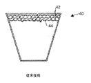
図2において示されるように、シートバスケット40(以下、単に「バスケット40」と呼ぶ)の一つの例は、熱伝達シート42がその中に積み重ねられる枠41を有している。限られた数の熱伝達シート42しか示されていないが、バスケット40は典型的には熱伝達シート42で満たされる、ということは理解されるべきである。図2においてまた見られるように、熱伝達シート42は、バスケット40の範囲内で空間を保った関係において近接して積み重ねられる。その結果として、隣接した熱伝達シート42の間の通路44が形成される。運転されている間において、空気もしくは排気ガスは、通路44を通って流れる。
As shown in FIG. 2, one example of a seat basket 40 (hereinafter simply referred to as “
図1および図2の両方に示されるように、加熱された排気ガスの流れ36は、熱交換器10のガスの区域を通るように仕向けられ、熱を熱伝達シート42に伝達する。熱伝達シート42は、その後、軸18の周りに回転して熱交換器10の空気の区域の所まで移動する。そこでは、燃焼用空気38が熱伝達シート42の上に沿って導かれ、そこで加熱される。
As shown in both FIGS. 1 and 2, the heated
図3および4においては、積み重ねられた状態の従来の熱伝達シート42が示されている。典型的には、熱伝達シート42は、1以上の畝50(または、「V字形の部材」としても知られる)および部分的には波打つような頂53によって画定された波状表面52を有するように形作られたスチールの平面部材である。波打つような頂53は、交互にうねるように(または、「波形」としても知られる)、上方および下方に延伸する。
3 and 4, a conventional
熱伝達シート42はまた、複数のより大きな畝50を有する。より大きな畝50は各々、畝の頂51を有しており、畝の頂51は一般的に等しい間隔で配置され、互いに隣接して積み重ねられた場合に隣接する熱伝達シート42の間の間隔が維持されるように機能する。そして、一緒になって、通路(図2の44)の側面を形成する。これらは、熱伝達シート42の間の空気もしくは排気ガスの流れを収容する。従来技術の熱伝達シート42において波状表面52を画定する波打つような頂53は、全て同じ高さである。図4において示されるように、より大きな畝50は、ローター(図1の12)を通過する空気もしくはガスの流れに対して予め決められた角度(例えば、0度)で延伸する。
The
従来技術において波状表面52を画定する波打つような頂53は、より大きな畝に対して同じ角度Auで配置されている。それゆえ、「空気の流れ」と記されている矢印によって指定される空気もしくは排気ガスの流れに対して同じ角度を保っている。波状表面52は、他のものの間で、通路(図2の44)を通過して流れる空気もしくは排気ガスの中の乱れを増加させるように、そしてそれにより熱伝達シート42の表面の温度境界層を乱すように機能する。このようなやり方で、波状表面52は、熱伝達シート42と空気もしくは排気ガスとの間の熱伝達を促進する。
In the prior art, the undulating
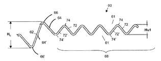
図5乃至7に示されるように、新規な熱伝達シート60は、熱伝達流体(以下、「空気もしくは排気ガス」と呼ぶ)の流れの方向に対して実質的に平行な長さLを有しており、先端80から後端90まで延伸する。「先端」および「後端」という用語は、以下便宜的に使用される。それらは、「空気の流れ」と記され矢印によって指定されるシート60を縦断する熱い空気の流れに関連している。
As shown in FIGS. 5-7, the novel
熱伝達シート60は、回転再生式熱交換器において従来技術の熱伝達シート42の代わりに用いられる。例えば、熱伝達シート60は、回転再生式熱交換器において用いられるために、バスケット40の中に積み重ねられ挿入されるかもしれない。
The
熱伝達シート60は、そこにおいて形成されるシート隔離部材59を有する。シート隔離部材59は、シート60がバスケット40(図2)に積み重ねられる場合に、シート60の間の望ましい空間の距離に影響を与え、隣接する熱伝達シート60の間の流路61を形成する。シート隔離部材59は、熱伝達シート(図5のL)の長さ方向に実質的に沿って、そして熱交換器のローターを通過する空気もしくは排気ガスの流れの方向に実質的に平行に、間隔を保つような関係において延伸している。各々の流路61は、先端80から後端90まで隣接する畝62の間を通って、シート60の全長Lに沿って延伸している。
The
図6および7に示される具体例において、シート隔離部材59は、畝62として示されている。各々の畝62は、第1の脈部64および第2の脈部64’によって画定される。第1の脈部64は、頂66’から外側に導かれる頂66(頂部)を画定している。そして、頂66’は、一般的に反対の方向にある第2の脈部64’によって画定されている。頂66と頂66’との間の一つの畝62の全体的な高さは、各々HLである。畝62の頂66と頂66’は、隣接する熱伝達シート60と係合し、隣接する熱伝達シートの間の間隔を維持する。熱伝達シート60は、一つの熱伝達シートの上の畝62が支持するための隣接する熱伝達シートの上の畝62の間の概ね半分に位置するように、配置される。
In the example shown in FIGS. 6 and 7, the
2つの異なる種類の波形を単一のシートの上に設置する方法は今まで知られていなかったので、これは産業における重要な進歩である。本発明は、波形の区域の間を連結させたり溶接したりすることを要せずにそれを成し遂げた。 This is an important advancement in the industry, as it has not been known until now how to place two different types of corrugations on a single sheet. The present invention accomplishes this without the need to connect or weld between corrugated areas.
シート隔離部材59は、シート60の間の望ましい間隔に影響を与え、隣接する熱伝達シート60の間の流路61を形成するために、その他の形をとるかもしれない、ということはまた熟考されることになる。
It is also contemplated that the
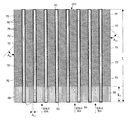
図11および12において示されるように、熱伝達シート60は、平板な領域88を長手方向に延伸させる形状のシート隔離部材59を有するかもしれない。平板な領域88は、隣接する熱伝達シートの畝62に対して実質的に平行であり、均等に間隔を隔てられている。その隣接する熱伝達シートの畝62上に、隣接する熱伝達シートの畝62が配置される。畝62のように、平板な領域88は、熱伝達シート60の全長Lに実質的に沿って延伸する。例えば、図11に示されるように、シート60は、交互に現れる畝62および平板な領域88を有するかもしれない。もう一つの方法として、図12に示されるように、一つの熱伝達シート60は、全ての長手方向に延伸する平板な領域88を有するかもしれない。この場合、他の熱伝達シート60は、全ての畝62を有する。
As shown in FIGS. 11 and 12, the
今度はまた図5乃至7に示されるように、いくつかの波状表面68および70は、シート隔離部材59の間の熱伝達シート60の上に配置される。各々の波状表面68は、シート隔離部材59の間の他の波状表面68に対して実質的に平行に延伸する。
In turn, as shown in FIGS. 5-7, several undulating
図6に示されるように、各々の波状表面68は、脈部(波形状もしくはひだ)72、72’によって画定される。各々の脈部72、72’は、図5において示されるように頂74、74’に沿って画定される方向において、熱伝達シート60に沿って延伸する。各々の波状表面68は、頂から頂までの高さがHu1である。
As shown in FIG. 6, each
図5および7に示されるように、各々の波状表面70は、シート隔離部材59の間の他の波状表面70と実質的に平行なように延伸している。各々の波状表面70は、他の脈部(波形状もしくはひだ)76’から反対の方向に突出している一つの脈部(波形状もしくはひだ)76を有している。各々の脈部76、76’は、各々の頂78、78’を有する流路61を部分的に画定する。そして、各々の脈部76、76’は、図6に示されるように、頂74、74’に沿って画定される方向において、熱伝達シート60に沿って延伸する。各々の波状表面70は、頂から頂までの高さがHu2である。
As shown in FIGS. 5 and 7, each
波状表面68の脈部72、72’は、波状表面70の脈部76、76’とは異なった角度において延伸している。それは、シート隔離部材59に対してであり、各々は角度Au1および角度Au2によって示されている。
The
シート隔離部材59は、一般的に熱伝達シート60における空気もしくは排気ガスの主たる流れの方向に対して平行である。図5に示されるように、波状表面68の流路は、シート隔離部材59の方向と実質的に平行に延伸している。そして、波状表面70の流路は、波形状の頂78として同じ方向において角度が付けられている。示されるように、もしAu1がゼロ度であるならば、この具体例におけるAu2は約45度である。対照的に、図4に示されるように、従来技術の熱伝達シート42における波状表面52は皆、隣接するシート隔離部材59に対して同一の角度Auで延伸する。
The
ここで説明される角度は、実施例を示すためにのみ設けられている。本発明は、広い多様な角度を包含する、ということが理解されるべきである。 The angles described here are provided only to illustrate the examples. It should be understood that the present invention encompasses a wide variety of angles.
図5(および図8)の波状表面68の長さL1は、熱伝達流体の流れ、望ましい熱伝達、その領域の位置などのような要素に基づいて選ばれるかもしれない。そこにおいては、硫酸、濃縮された物質、および粒子状物質が、熱伝達の表面にたまり、清掃のために望ましい煤煙ブロワの浸食が生じる。煤煙ブロワは、熱伝達シートを清掃するために用いられてきた。これらは高い圧力の空気もしくは蒸気の突風を、積み重ねられた要素の間の流路(図2の44、図6、7、11、12の61)に流し、熱伝達シートの表面から粒子の沈着を除去する。作動中において熱伝達の表面の上に形成されるであろう沈着物を除去することを助けるために、全てのもしくは一部分の沈着物が、熱交換器のローターを通過する空気もしくは排気ガス(図1の36、38)の流れの方向に実質的に平行な熱伝達シートの区域に位置するように、L1の距離を選択することが望ましいだろう。しかしながら、好ましくは、L1は熱伝達シート60の全長Lの3分の1未満、さらに望ましくは熱伝達シート60の全長Lの4分の1未満であるかもしれない。このことは、十分な量の波状表面70をもたらし、熱伝達流体の流れを乱流として発達させる。その結果として、乱流は、波状表面70の全長に渡り続くことになる。波状表面70は、運転条件の全ての範囲において耐えられるように十分に硬く作られるべきである。それには、熱伝達シート60に対する煤煙ブロワの噴流による清掃も含まれる。
The length L 1 of the
ここで説明される長さは、実施例を示すためにのみ設けられている。本発明が広い多様な長さおよび長さの比率を包含する、ということは理解されるべきである。 The lengths described here are provided only to illustrate the examples. It should be understood that the present invention encompasses a wide variety of lengths and length ratios.
一般的に、燃料中の硫黄の量が多いほど、最適な性能を発揮するためにより長いL1(およびL2、L3)が採用されるべきである。また、空気を予熱する機器からのガスの出口温度が低ければ低いほど、最適な性能を発揮するためにより長いL1(およびL2、L3)が採用されるべきである。 In general, the greater the amount of sulfur in the fuel, the longer L 1 (and L 2 , L 3 ) should be employed for optimal performance. Also, the lower the exit temperature of the gas from the equipment that preheats the air, the longer L 1 (and L 2 , L 3 ) should be employed to achieve optimal performance.
再び図6および7を参照して、Hu1およびHu2は同じであるかもしれない、ということは熟考されるべきである。あるいは、Hu1およびHu2は異なるかもしれない。例えば、Hu1がHu2よりも短かもしれないが、Hu1およびHu2は両方ともHLよりも短い。対照的に、図4に示されるように、従来技術の熱伝達シート42における波状表面52は、皆同じ高さである。
Referring again to FIGS. 6 and 7, it should be considered that H u1 and H u2 may be the same. Alternatively, H u1 and H u2 may be different. For example, H u1 may be shorter than H u2 , but H u1 and H u2 are both shorter than H L. In contrast, as shown in FIG. 4, the
本発明者たちによる数値流体力学のモデリングは、図5の具体例が流路(図6および7の61)の範囲内におけるより深い位置に対してより高い煤煙ブロワの噴流の速度および運動エネルギーを維持することを許容する、ということを示した。それは、より良い清掃をもたらすことが予期される。 The modeling of computational fluid dynamics by the inventors has shown that the embodiment of FIG. 5 shows higher jet blower jet velocity and kinetic energy for deeper positions within the flow path (61 in FIGS. 6 and 7). It was shown that it was allowed to maintain. It is expected to provide better cleaning.
図5の具体例は、煤煙ブロワの噴流によるより良い清掃を可能にすると思われ、もしくは潜在的に熱伝達の表面の上のより粘性の高い沈着物を清掃することを可能にすると思われる。なぜならば、波状表面68は、先端80へ向けられる噴流とより上手くその方向が揃っており、それにより流路(図6、7の61)に沿った煤煙ブロワの噴流のより大きな浸食を可能とするからである。
The embodiment of FIG. 5 may allow better cleaning with a jet of smoke blower, or potentially allow cleaning of more viscous deposits on heat transfer surfaces. This is because the
さらに、波状表面68の形状が熱伝達シート60の間のより良い見通し線を提供する場合、ここで説明される熱伝達シートは赤外線(ホットスポット)探知器とより一貫性のあるものとなる。
Further, if the shape of the
図5の具体例は、煤煙ブロワ試験において振動に対して影響を受けにくいことを証明した。一般的に、熱伝達シートの振動は望ましくない。なぜなら、それはシートの過剰な変形をもたらすからである。それに加えて、それはシートが互いに擦れて、それゆえシートの有効寿命の減少をもたらすためである。波状表面68の方向は実質的に煤煙ブロワの噴流(空気の流れ)の方向と揃っているので、煤煙ブロワの噴流の速度および運動エネルギーは、流路(図6および7の61)に沿ったより深い位置に対して失われずに保持されている。これは、より多くのエネルギーが熱伝達の表面の上の沈着物を除去するために利用可能であることをもたらす。
The example of FIG. 5 proved to be less susceptible to vibration in the soot blower test. In general, vibration of the heat transfer sheet is undesirable. This is because it leads to excessive deformation of the sheet. In addition, it is because the sheets rub against each other, thus reducing the useful life of the sheet. Since the direction of the
図8は、3つの表面の幾何学的形状を組み合わせる熱伝達シート160の別の具体例を示している。熱伝達シート60に類似したやり方において、熱伝達シート160は、一連のシート隔離部材59を間隔を置いて有している。その一連のシート隔離部材59は、長手方向に延伸し、熱交換器を通過する空気もしくは排気ガスの流れの方向に対して実質的に平行である。
FIG. 8 shows another embodiment of a
熱伝達シート160はまた、波状表面68および70を有している。ここで、波状表面68は、熱伝達シート160の先端80および後端90の両方の上に配置されている。図6乃至8において示されるように、波状表面68の脈部72は、シート隔離部材59に対して角度Au1によって表現される第1の方向へ延伸している。ここで、Au1はゼロである。なぜなら、シート隔離部材59は、脈部72と平行だからである。波状表面70の脈部76は、シート隔離部材59に対して第2の方向Au2において延伸している。
The
しかしながら、本発明は、これによって限定されるものでなく、シート60の後端90における波状表面68は、先端80における波状表面68と異なるように角度を付けられているかもしれない。波状表面68の高さもまた、波状表面70の高さと比較して異なるかもしれない。例えば、後端90における波状表面68の長さL3と先端80における波状表面68の長さL2との和は、熱伝達シート60の長さLの2分の1よりも短い。好ましくは、それは、熱伝達シート60の全長Lの3分の1以下である。図8の熱伝達シート160が、例えば、用いられるかもしれない。そこにおいては、煤煙ブロワは先端80および後端90の両方に向けられているかもしれない。
However, the present invention is not so limited, and the
本発明の熱伝達シートは、各々の流路61の長さに沿っていくつかの異なる数の表面の幾何学的形状を有するかもしれない。例えば、図9は、3つの異なる表面の幾何学的形状を組み合わせた熱伝達シート260を描写している。熱伝達シート60および160に類似したやり方で、熱伝達シート260は一定の間隔でシート隔離部材59を有している。このシート隔離部材59は、長手方向でありかつ熱交換器のローターを通過する空気もしくは排気ガスの流れの方向に対して平行な方向に延伸し、隣接するシート260の間の流路61を画定する。
The heat transfer sheet of the present invention may have several different numbers of surface geometries along the length of each
熱伝達シート260はまた、波状表面68、70、および71を有する。ここで、波状表面68は、先端80の上に配置されている。示されるように、波状表面68の脈部72は、角度Au1によって代表される第1の方向(示されるように、例えば、シート隔離部材59に対して平行)に延伸する。波状表面70の脈部76は、シート隔離部材59に対して角度Au2の第2の方向において、熱伝達シート260の一部分に渡って延伸している。そして、波状表面71の脈部73は、シート隔離部材59に対して角度Au3の第3の方向において、熱伝達シート260の一部分に渡って延伸している。ここで、Au3は、Au2やAu1と異なっている。例えば、Au3は、シート隔離部材59に対してAu2とは反対側の(反射するような)角度であるかもしれない。ここにおいて開示される他の具体例と同じように、波状表面68、70、および71の高さHu1およびHu2は、異なっているかもしれない。
The
図示されるように、波状表面70および71は、熱伝達シート260に沿って交互に行ったり来たりする。それによって、熱伝達流体が流れるに従ってその乱れが増加する。流体の乱れは熱伝達シート260に対してより長い時間だけ接触することにより生じ、それゆえ熱伝達を促進する。旋回流はまた、流れている流体を混合するのに役立ち、より一様な流れの温度を提供する。
As shown, the
この乱流は、最小の圧力降下を伴って熱伝達シート60の熱伝達率を高めると信じられている。一方で、伝達される総熱量を著しく高める。
This turbulence is believed to increase the heat transfer rate of the
図10に示されるように、熱伝達シート360は、複数の脈部376に沿って連続的に変化する表面の幾何学的形状を組み入れる。熱伝達シート60、160、および260に類似するやり方で、熱伝達シート360は間隔を置いてシート隔離部材59を有する。このシート隔離部材59は、長手方向でありかつ熱交換器のローターを通過する空気もしくは排気ガスの流れの方向に実質的に平行な方向に延伸し、隣接するシート360の間の図6および7の流路61などのような流路を画定する。
As shown in FIG. 10, the
(図6、7、11、および12の流路61に類似する)流路は、波状表面368の脈部376の下のシート隔離部材59の間に設けられる。脈部376は、先端80から後端90までのシート360の全長Lに渡り、シート隔離部材59に対して徐々に角度を増していくようになる。この構成は、従来技術の設計と比較して、煤煙ブロワの噴流が先端80から流路のより深い距離まで浸食することを可能にする。
A flow path (similar to the
この設計はまた、後端90の近くにおいてより大きな熱伝達および流体の乱れを披瀝する。波状表面368における漸進的な角度の変化は、異なる角度の波状表面に対して鋭く遷移することの必要性を回避することができる。一方、今までのものと同様に、波状表面が煤煙ブロワの噴流と協力して、より深い浸食およびより優れた清掃を可能にすることができる。波状表面368の高さはまた、熱伝達シート360の全長Lにそって変化するかもしれない。
This design also demonstrates greater heat transfer and fluid turbulence near the
図11は、同じ参照番号を伴った部分が図6および7において説明されたものと同じ機能を有する代替的な具体例を示している。この具体例において、平板な部分88は頂66および66’と接触しており、各々のシート隔離部材の左側および右側の上の流路61の間のより効果的な密封を生み出している。流路は、「閉じた流路」として言及される。
FIG. 11 shows an alternative embodiment in which parts with the same reference numbers have the same functions as those described in FIGS. In this embodiment, the
図12は、同じ参照番号を伴った部分が前の図面において説明されたものと同じ機能を有する別の代替的な具体例を示している。この具体例は、シート隔離部材59が中央の熱伝達シートの上にのみ設けられているという点において、図11と異なる。
FIG. 12 shows another alternative embodiment in which parts with the same reference numbers have the same functions as those described in the previous drawings. This example differs from FIG. 11 in that the
図13は、同じシート上に2つの異なる表面の幾何学的形状が配置された別の例を示す熱伝達シートの上面図である。前の図面のものと同じ参照番号が付されている部分は、同じ機能を有する。この具体例は、図5のものと類似している。この具体例において、隣接する波状表面70、79は、シート隔離部材59に関して反対側となる角度を付けられた頂78、81を有する。波のような頂78は、シート隔離部材59に対して角度Au2を有する。波のような頂81は、シート隔離部材59に対して角度Au4を有する。
FIG. 13 is a top view of a heat transfer sheet showing another example in which two different surface geometries are arranged on the same sheet. Parts denoted by the same reference numerals as those in the previous drawings have the same functions. This example is similar to that of FIG. In this embodiment, adjacent
しかしながら、図13は、次のことを図示する目的で用いられる。すなわち、本発明は、互いに反対側に並べられた脈部の角度を伴って各々方向付けられた隣接する波のような平行な脈部の区域を有する、ということは記述されるべきである。 However, FIG. 13 is used to illustrate: That is, it should be described that the present invention has areas of parallel veins, such as adjacent waves, each oriented with angles of the veins arranged opposite to each other.
本発明が例示的な具体例に関して説明されてきた一方で、本発明の技術的思想の範囲内において様々な変形例が作られ、また各要素が他の異なる要素によって代替され得るということが、当業者によって理解されるだろう。それに加えて、特定の装置、状況、もしくは材料に当てはめるために、本発明の技術的思想の範囲内で、多くの修正が行なわれ得ることが、当業者によって理解されるだろう。それゆえ、本発明は、本発明を実行するために熟考されたベストモードとして開示された特定の具体例に限定されるものではない、ということが意図されている。また、本発明は添付されているクレームの範囲内に含まれる全ての具体例を含むだろう、ということも意図されている。 While the invention has been described in terms of exemplary embodiments, it will be understood that various modifications may be made within the scope of the invention and that each element may be replaced by other different elements. It will be understood by those skilled in the art. In addition, it will be appreciated by those skilled in the art that many modifications may be made within the scope of the inventive concept to apply to a particular device, situation, or material. Therefore, it is intended that the invention is not limited to the specific embodiments disclosed as the best mode contemplated for carrying out the invention. It is also intended that the present invention will include all embodiments that fall within the scope of the appended claims.
10…回転再生式熱交換器、12…ローター、14…ハウジング、16…仕切り、17…小区分、18…軸、20…燃焼排気ガスの入口ダクト、22…燃焼排気ガスの出口ダクト、24…空気の入口ダクト、26…空気の出口ダクト、28…扇形板、36…燃焼排気ガス、38…燃焼用空気、40…バスケット、42…熱伝達シート、44…熱伝達シートの間の通路、50…畝、51…頂、52…波状表面、53…頂、59…シート隔離部材、60…熱伝達シート、61…流路、62…畝、64…脈部、64’…脈部、66…頂、66’…頂、68…波状表面、70…波状表面、72…脈部、72’…脈部、74…頂、74’…頂、76…脈部、76’…脈部、78…頂、78’…頂、79…波状表面、80…先端、81…頂、88…平板な領域、90…後端、160…熱伝達シート、260・・・熱伝達シート、360…熱伝達シート、368…波状表面、376…脈部
DESCRIPTION OF
Claims (13)
ガスの流れの方向に対して平行に延伸し、且つ前記熱伝達シートに沿って前記熱伝達シートの先端から前記先端とは反対の後端への一方向に延伸し、隣接する熱伝達シートとの間に流路の一部を画定する複数のシート隔離部材と、
互いに隣接する2つの前記シート隔離部材の間の各々に各々配置される複数の波状表面と
を備え、
前記複数の波状表面は、
前記熱伝達シートに沿って前記一方向に延伸し、前記シート隔離部材に対し第1の角度をなして互いに平行な複数の脈部によって所定の距離で形成される第1の波状表面と、
前記熱伝達シートに沿って、直接隣接する2つの前記シート隔離部材の間に連続して延伸し、前記シート隔離部材に対して前記第1の角度と異なる第2の角度をなして互いに平行な複数の脈部によって形成される第2の波状表面と
を含み、
前記複数の脈部は、直接隣接する2つの前記シート隔離部材の間に配置され且つ前記シート隔離部材よりも高さが低い頂をそれぞれ有し、
前記第1の波状表面の脈部は前記第1の角度をなして前記シート隔離部材に対し平行であり、前記第2の波状表面の脈部は、前記第2の角度をなして前記シート隔離部材に対し傾斜し、
前記熱伝達シートの表面上に形成されるであろう沈着物を除去することを助けるために、全てのもしくは一部分の沈着物が、前記熱伝達シートのうち、前記第1の波状表面の脈部を含む区域であって、前記回転再生式熱交換器を通過するガスの流れの方向に実質的に平行な区域に位置するように、前記第1の波状表面の前記所定の距離が選択される、
回転再生式熱交換器のための熱伝達シート。 A heat transfer sheet for a rotary regenerative heat exchanger,
Extending parallel to the direction of gas flow , and extending in one direction along the heat transfer sheet from the front end of the heat transfer sheet to the rear end opposite to the front end, and adjacent heat transfer sheets; A plurality of sheet isolating members defining a portion of the flow path between
A plurality of corrugated surfaces respectively disposed between each of the two sheet separating members adjacent to each other;
The plurality of wavy surfaces are
A first wavy surface formed at a predetermined distance by a plurality of veins extending in one direction along the heat transfer sheet and parallel to each other at a first angle with respect to the sheet separating member ;
Along the heat transfer sheet, it extends continuously between the two adjacent sheet separating members, and is parallel to each other at a second angle different from the first angle with respect to the sheet separating member. A second wavy surface formed by a plurality of veins,
Each of the plurality of veins is arranged between two directly adjacent sheet separating members and has a peak that is lower than the sheet separating member;
The ridges of the first wavy surface are parallel to the sheet separating member at the first angle , and the ridges of the second wavy surface are formed at the second angle to isolate the sheet. Inclined with respect to the member,
In order to help remove deposits that would have formed on the surface of the heat transfer sheet, all or a portion of the deposits of the heat transfer sheet may be a ridge of the first wavy surface. And the predetermined distance of the first corrugated surface is selected to be located in an area substantially parallel to the direction of gas flow through the rotary regenerative heat exchanger ,
Heat transfer sheet for rotary regenerative heat exchanger.
請求項1に記載の熱伝達シート。 The heat transfer sheet according to claim 1, wherein the first wavy surface is connected to the second wavy surface, and a flow path formed by the wavy surface is fluidly continuous and aligned.
請求項2に記載の熱伝達シート。 The heat transfer sheet according to claim 2, wherein the first wavy surface is located at an end of the heat transfer sheet.
前記シート隔離部材と平行である前記熱伝達シートに沿って延伸し、互いに平行な複数の脈部によって形成される第3の波状表面を含み、
前記第3の波状表面は前記熱伝達シートにおいて前記第1の波状表面とは反対側の端部に位置する
請求項2に記載の熱伝達シート。 The plurality of wavy surfaces are
Extending along the heat transfer sheet that is parallel to the sheet isolation member, and includes a third wavy surface formed by a plurality of pulses parallel to each other;
The heat transfer sheet according to claim 2, wherein the third wavy surface is located at an end of the heat transfer sheet opposite to the first wavy surface.
前記第2の波状表面を形成する脈部の各々は上側の頂および下側の頂を有し、
前記第1の波状表面の頂の間の平均的な距離は、前記第2の波状表面の頂の間の平均的な距離と異なる
請求項1に記載の熱伝達シート。 Each of the veins forming the first wavy surface has an upper apex and a lower apex;
Each of the veins forming the second wavy surface has an upper apex and a lower apex;
The heat transfer sheet according to claim 1, wherein an average distance between the tops of the first wavy surfaces is different from an average distance between the tops of the second wavy surfaces.
請求項1に記載の熱伝達シート。 The heat transfer sheet according to claim 1, wherein the sheet separating member has at least one of a flange portion and a flat portion.
ガスの流れの方向に対して平行に延伸し、且つ熱伝達シートに沿って前記熱伝達シートの先端から前記先端とは反対の後端への一方向に延伸し、隣接する熱伝達シートとの間に流路の第1の部分を画定する第1のシート隔離部材と、
前記第1のシート隔離部材に対して平行に延伸し、且つ前記熱伝達シートに沿って前記熱伝達シートの先端から前記先端とは反対の後端への一方向に延伸し、流路の第2の部分を画定する第2のシート隔離部材と、
前記第1のシート隔離部材と前記第2のシート隔離部材との間の前記熱伝達シートの上に連続して配置され、前記一方向において前記熱伝達シートに沿って延伸し前記第1のシート隔離部材および前記第2のシート隔離部材に対して第1の角度をなして互いに平行な複数の脈部によって形成され、流路の第3の部分を画定する第1の波状表面と、
前記第1のシート隔離部材と前記第2のシート隔離部材との間の前記熱伝達シートの上に所定の距離で配置され、前記熱伝達シートに沿って延伸し互いに平行な複数の脈部によって形成され、流路の第4の部分を画定する第2の波状表面と
を備え、
前記複数の脈部は、直接隣接する2つの前記シート隔離部材の間に配置され且つ前記シート隔離部材よりも高さが低い頂をそれぞれ有し、
前記第2の波状表面の脈部は前記第1のシート隔離部材および前記第2のシート隔離部材に対し平行であり、前記第1の波状表面の脈部は、前記第2の角度をなして前記シート隔離部材に対し傾斜し、
前記熱伝達シートの表面上に形成されるであろう沈着物を除去することを助けるために、全てのもしくは一部分の沈着物が、前記熱伝達シートのうち、前記第2の波状表面の脈部を含む区域であって、前記回転再生式熱交換器を通過するガスの流れの方向に実質的に平行な区域に位置するように、前記第2の波状表面の前記所定の距離が選択される、
回転再生式熱交換器のための熱伝達シート。 A heat transfer sheet for a rotary regenerative heat exchanger,
Extending parallel to the direction of gas flow , and extending in one direction along the heat transfer sheet from the front end of the heat transfer sheet to the rear end opposite to the front end. A first sheet isolation member defining a first portion of the flow path therebetween;
Extending parallel to the first sheet separating member and extending in one direction along the heat transfer sheet from the front end of the heat transfer sheet to the rear end opposite to the front end . A second sheet isolating member defining two portions;
The first sheet is continuously disposed on the heat transfer sheet between the first sheet isolation member and the second sheet isolation member, and extends along the heat transfer sheet in the one direction. A first wavy surface formed by a plurality of veins parallel to each other at a first angle with respect to the isolation member and the second sheet isolation member; and defining a third portion of the flow path;
A plurality of ridges disposed at a predetermined distance on the heat transfer sheet between the first sheet isolation member and the second sheet isolation member, extending along the heat transfer sheet and parallel to each other A second wavy surface formed and defining a fourth portion of the flow path,
Each of the plurality of veins is arranged between two directly adjacent sheet separating members and has a peak that is lower than the sheet separating member;
The ridges of the second wavy surface are parallel to the first sheet isolation member and the second sheet isolation member, and the ridges of the first wavy surface form the second angle. Inclined with respect to the sheet separating member,
In order to help remove deposits that would have formed on the surface of the heat transfer sheet, all or a portion of the deposits of the heat transfer sheet may be a ridge of the second wavy surface. The predetermined distance of the second corrugated surface is selected to be located in an area that includes substantially parallel to a direction of gas flow through the rotary regenerative heat exchanger ,
Heat transfer sheet for rotary regenerative heat exchanger.
請求項7に記載の熱伝達シート。 The heat transfer sheet according to claim 7 , wherein the second wavy surface is located at an end of the heat transfer sheet.
前記第3の波状表面は、互いに平行であり、前記第1のシート隔離部材および前記第2のシート隔離部材と平行な前記熱伝達シートに沿って延伸する複数の脈部によって形成され、
前記第3の波状表面は、前記熱伝達シートにおける前記第2の波状表面とは反対側の端部に位置し、
前記第1の波状表面は前記第2の波状表面と前記第3の波状表面との間に位置する
請求項7に記載の熱伝達シート。 A third corrugated surface disposed on the heat transfer sheet between the first sheet isolation member and the second sheet isolation member and defining a fifth portion of the flow path;
The third wavy surface is formed by a plurality of veins extending along the heat transfer sheet that are parallel to each other and parallel to the first sheet isolation member and the second sheet isolation member;
The third wavy surface is located at an end of the heat transfer sheet opposite to the second wavy surface;
The heat transfer sheet according to claim 7 , wherein the first wavy surface is located between the second wavy surface and the third wavy surface.
請求項7に記載の熱伝達シート。 A plurality of first wavy surfaces; and a plurality of fourth wavy surfaces arranged alternately with the plurality of first wavy surfaces, wherein the fourth wavy surfaces are parallel to each other. The heat transfer sheet according to claim 7 , wherein the pulsation part included in the first undulating surface and the pulsation part included in the fourth undulating surface extend at different angles.
請求項7に記載の熱伝達シート。 The heat transfer sheet according to claim 7 , wherein a height between the tops of the veins forming the first wavy surface is different from a height between the tops of the veins forming the second wavy surface.
請求項7に記載の熱伝達シート。 The heat transfer sheet according to claim 7 , wherein each of the first sheet isolation member and the second sheet isolation member has at least one of a flange portion and a flat portion.
請求項7に記載の熱伝達シート。 The heat transfer sheet according to claim 7 , wherein the sheet isolation member has a flat portion that forms a closed flow path.
Applications Claiming Priority (3)
| Application Number | Priority Date | Filing Date | Title |
|---|---|---|---|
| US12/437,914 | 2009-05-08 | ||
| US12/437,914 US9557119B2 (en) | 2009-05-08 | 2009-05-08 | Heat transfer sheet for rotary regenerative heat exchanger |
| PCT/US2010/027076 WO2010129092A1 (en) | 2009-05-08 | 2010-03-12 | Heat transfer sheet for rotary regenerative heat exchanger |
Related Child Applications (1)
| Application Number | Title | Priority Date | Filing Date |
|---|---|---|---|
| JP2014108278A Division JP5908027B2 (en) | 2009-05-08 | 2014-05-26 | Heat transfer sheet for rotary regenerative heat exchanger |
Publications (3)
| Publication Number | Publication Date |
|---|---|
| JP2012526262A JP2012526262A (en) | 2012-10-25 |
| JP2012526262A5 JP2012526262A5 (en) | 2013-10-10 |
| JP5656979B2 true JP5656979B2 (en) | 2015-01-21 |
Family
ID=42235419
Family Applications (2)
| Application Number | Title | Priority Date | Filing Date |
|---|---|---|---|
| JP2012509814A Expired - Fee Related JP5656979B2 (en) | 2009-05-08 | 2010-03-12 | Heat transfer sheet for rotary regenerative heat exchanger |
| JP2014108278A Active JP5908027B2 (en) | 2009-05-08 | 2014-05-26 | Heat transfer sheet for rotary regenerative heat exchanger |
Family Applications After (1)
| Application Number | Title | Priority Date | Filing Date |
|---|---|---|---|
| JP2014108278A Active JP5908027B2 (en) | 2009-05-08 | 2014-05-26 | Heat transfer sheet for rotary regenerative heat exchanger |
Country Status (17)
| Country | Link |
|---|---|
| US (3) | US9557119B2 (en) |
| EP (2) | EP2667138B1 (en) |
| JP (2) | JP5656979B2 (en) |
| KR (2) | KR101316776B1 (en) |
| CN (2) | CN102422112B (en) |
| AU (2) | AU2010245218A1 (en) |
| BR (1) | BRPI1014805A8 (en) |
| CA (2) | CA2759895C (en) |
| DK (2) | DK2667138T3 (en) |
| ES (2) | ES2553000T3 (en) |
| IL (2) | IL215250A (en) |
| MX (1) | MX339981B (en) |
| PL (1) | PL2427712T3 (en) |
| SG (2) | SG174884A1 (en) |
| TW (2) | TWI398618B (en) |
| WO (1) | WO2010129092A1 (en) |
| ZA (2) | ZA201107086B (en) |
Families Citing this family (18)
| Publication number | Priority date | Publication date | Assignee | Title |
|---|---|---|---|---|
| DE102006003317B4 (en) | 2006-01-23 | 2008-10-02 | Alstom Technology Ltd. | Tube bundle heat exchanger |
| US9557119B2 (en) | 2009-05-08 | 2017-01-31 | Arvos Inc. | Heat transfer sheet for rotary regenerative heat exchanger |
| US9644899B2 (en) * | 2011-06-01 | 2017-05-09 | Arvos, Inc. | Heating element undulation patterns |
| US9200853B2 (en) * | 2012-08-23 | 2015-12-01 | Arvos Technology Limited | Heat transfer assembly for rotary regenerative preheater |
| TWI496918B (en) * | 2013-02-05 | 2015-08-21 | Adpv Technology Ltd Intetrust | Gas release device for coating process |
| MX368708B (en) * | 2013-09-19 | 2019-10-11 | Howden Uk Ltd | Heat exchange element profile with enhanced cleanability features. |
| US10175006B2 (en) | 2013-11-25 | 2019-01-08 | Arvos Ljungstrom Llc | Heat transfer elements for a closed channel rotary regenerative air preheater |
| US9856983B2 (en) | 2013-12-10 | 2018-01-02 | Howden Thomassen Compressors Bv | Single seal ring stuffing box |
| EP2908080A1 (en) * | 2014-02-13 | 2015-08-19 | Ekocoil Oy | Heat exchanger structure for reducing accumulation of liquid and freezing |
| US10094626B2 (en) * | 2015-10-07 | 2018-10-09 | Arvos Ljungstrom Llc | Alternating notch configuration for spacing heat transfer sheets |
| SE541591C2 (en) * | 2016-02-24 | 2019-11-12 | Alfa Laval Corp Ab | A heat exchanger plate for a plate heat exchanger, and a plate heat exchanger |
| DE102016205353A1 (en) * | 2016-03-31 | 2017-10-05 | Mahle International Gmbh | The stacked-plate heat exchanger |
| US10267517B2 (en) * | 2016-07-08 | 2019-04-23 | Arvos Ljungstrom Llc | Method and system for improving boiler effectiveness |
| TWI707121B (en) * | 2016-10-11 | 2020-10-11 | 美商傲華公司 | An alternating notch configuration for spacing heat transfer sheets |
| US10578367B2 (en) | 2016-11-28 | 2020-03-03 | Carrier Corporation | Plate heat exchanger with alternating symmetrical and asymmetrical plates |
| WO2018125134A1 (en) * | 2016-12-29 | 2018-07-05 | Arvos, Ljungstrom Llc. | A heat transfer sheet assembly with an intermediate spacing feature |
| US10837714B2 (en) | 2017-06-29 | 2020-11-17 | Howden Uk Limited | Heat transfer elements for rotary heat exchangers |
| PL235069B1 (en) * | 2017-12-04 | 2020-05-18 | Ts Group Spolka Z Ograniczona Odpowiedzialnoscia | Coil for transmission of heat for the rotary, cylindrical heat exchanger |
Family Cites Families (209)
| Publication number | Priority date | Publication date | Assignee | Title |
|---|---|---|---|---|
| US682607A (en) | 1899-11-22 | 1901-09-17 | Joseph Eck | Roller for calendering-machines. |
| US1477209A (en) | 1919-05-05 | 1923-12-11 | George Henry De Vore | Radiator for automobiles |
| US1429149A (en) | 1920-10-18 | 1922-09-12 | Engineering Dev Company | Heat interchanger |
| US1524280A (en) | 1920-11-09 | 1925-01-27 | Ingersoll Rand Co | Condenser tube terminal |
| GB177780A (en) | 1921-04-01 | 1923-02-15 | Armin Renyi | Improvements in rolling mills for manufacturing corrugated pasteboard, sheet metal and the like |
| US1450351A (en) | 1922-04-22 | 1923-04-03 | Beran Albert | Rolling mill for manufacturing corrugated pasteboard, sheet metal, and the like |
| US1894956A (en) | 1929-01-16 | 1933-01-24 | Babcock & Wilcox Co | Air heater |
| US2023965A (en) | 1930-05-21 | 1935-12-10 | Ljungstroms Angturbin Ab | Heat transfer |
| US1915742A (en) | 1930-11-28 | 1933-06-27 | Manuf Generale Metallurg Sa | Heat exchange apparatus |
| US1987798A (en) | 1931-05-19 | 1935-01-15 | Ruppricht Siegfried | Thermal insulating material |
| US1875188A (en) | 1932-01-27 | 1932-08-30 | Sherman Products Corp | Unit formed of sheet material |
| FR775271A (en) | 1934-05-25 | 1934-12-22 | Cooling radiator for heat engine of motor cars or other similar applications | |
| US2042017A (en) | 1934-08-24 | 1936-05-26 | Orchard Paper Co | Decorative corrugated paper |
| US2313081A (en) | 1937-02-02 | 1943-03-09 | Jarvis C Marble | Heat exchange |
| US2102936A (en) | 1937-03-09 | 1937-12-21 | David C Bailey | Window glass guide |
| US2160677A (en) | 1937-09-15 | 1939-05-30 | Hippolyte W Romanoff | Reinforced corrugated sheet |
| US2438851A (en) | 1943-11-01 | 1948-03-30 | Air Preheater | Plate arrangement for preheaters |
| US2432198A (en) | 1945-01-12 | 1947-12-09 | Air Preheater | Heat exchange surface for air preheaters |
| SE127755C1 (en) * | 1945-05-28 | 1950-03-28 | Ljungstroms Angturbin Ab | Element set for heat exchangers |
| US2940736A (en) * | 1949-05-25 | 1960-06-14 | Svenska Rotor Maskiner Ab | Element set for heat exchangers |
| US2782009A (en) | 1952-03-14 | 1957-02-19 | Gen Motors Corp | Heat exchangers |
| US3262490A (en) | 1954-04-21 | 1966-07-26 | Chrysler Corp | Process for joining metallic surfaces and products made thereby |
| US2796157A (en) | 1956-05-18 | 1957-06-18 | Charles R Ginsburg | Structural panel construction |
| FR1219505A (en) | 1958-03-25 | 1960-05-18 | Zd Y V I | Elastic connection of heat exchanger tubes to the heat exchanger base |
| US3111982A (en) * | 1958-05-24 | 1963-11-26 | Gutehoffnungshuette Sterkrade | Corrugated heat exchange structures |
| US2983486A (en) | 1958-09-15 | 1961-05-09 | Air Preheater | Element arrangement for a regenerative heat exchanger |
| US3019160A (en) | 1959-05-11 | 1962-01-30 | Diamond Alkali Co | Haloglycoluril bactericidal compositions for disinfecting and bleaching |
| US3158527A (en) | 1960-06-10 | 1964-11-24 | Crown Zellerbach Corp | Plaited structure and method of forming same |
| GB959020A (en) | 1960-07-20 | 1964-05-27 | Apv Co Ltd | A new or improved heat exchanger plate |
| GB992413A (en) | 1961-05-25 | 1965-05-19 | Howden James & Co Ltd | Improvements relating to rotary regenerative air preheaters for boiler plant |
| GB984719A (en) | 1962-03-13 | 1965-03-03 | Atomic Energy Authority Uk | Improvements in or relating to heat exchangers |
| US3260511A (en) | 1962-07-20 | 1966-07-12 | Ici Ltd | Water cooling towers |
| US3183963A (en) * | 1963-01-31 | 1965-05-18 | Gen Motors Corp | Matrix for regenerative heat exchangers |
| SE307964B (en) | 1964-03-24 | 1969-01-27 | C Munters | |
| US3317222A (en) | 1964-04-16 | 1967-05-02 | Cons Edison Co New York Inc | Insert constructions for tubes of heat exchangers and condensers |
| US3373798A (en) | 1965-11-19 | 1968-03-19 | Gen Motors Corp | Regenerator matrix |
| US3550423A (en) | 1966-04-11 | 1970-12-29 | Wood Marc Sa | Method of making a sheet of material having asymmetrical folds |
| US3372743A (en) | 1967-01-25 | 1968-03-12 | Pall Corp | Heat exchanger |
| GB1196562A (en) | 1967-02-17 | 1970-07-01 | Hitachi Ltd | Welded Assembly of a Tube and a Tube Sheet |
| US3452814A (en) | 1967-02-24 | 1969-07-01 | Gen Electric | Bell-end condenser tubes |
| US3523058A (en) | 1968-04-05 | 1970-08-04 | Owens Illinois Inc | Fabricatable stiff-when-wet corrugated paperboard |
| US3542635A (en) | 1968-04-05 | 1970-11-24 | Chevron Res | Corrugated thermoplastic articles |
| US3490523A (en) | 1968-04-08 | 1970-01-20 | Us Health Education & Welfare | Transfer device |
| US3574103A (en) | 1968-09-06 | 1971-04-06 | Atomic Energy Commission | Laminated cellular material form |
| US3532157A (en) | 1969-01-03 | 1970-10-06 | Gen Motors Corp | Regenerator disk |
| US4449573A (en) * | 1969-06-16 | 1984-05-22 | Svenska Rotor Maskiner Aktiebolag | Regenerative heat exchangers |
| GB1339542A (en) | 1970-03-20 | 1973-12-05 | Apv Co Ltd | Plate heat exchangers |
| BE788776A (en) | 1970-05-07 | 1973-01-02 | Serck Industries Ltd | LIQUID COOLING DEVICE |
| US3674620A (en) | 1970-05-25 | 1972-07-04 | Butler Manufacturing Co | Reinforced plastic panel and method of making the same |
| AT319672B (en) | 1971-02-15 | 1975-01-10 | Muellender Gernot | Process for the production of foil sheets for lining pipe elbows |
| USRE28534E (en) | 1971-06-07 | 1975-08-26 | Stress oriented corrugations | |
| US3759323A (en) | 1971-11-18 | 1973-09-18 | Caterpillar Tractor Co | C-flow stacked plate heat exchanger |
| DE2219130C2 (en) | 1972-04-19 | 1974-06-20 | Ulrich Dr.-Ing. 5100 Aachen Regehr | CONTACT BODY FOR HEAT AND / OR SUBSTANCE EXCHANGE |
| US3830684A (en) | 1972-05-09 | 1974-08-20 | Hamon Sobelco Sa | Filling sheets for liquid-gas contact apparatus |
| GB1485369A (en) | 1973-12-05 | 1977-09-08 | Covrad Ltd | Apparatus for shaping sheet material |
| SE385971B (en) | 1973-12-20 | 1976-07-26 | Svenska Flaektfabriken Ab | CONTACT BODY FOR WATER AND AIR, MAINLY INTENDED FOR COOLING TOWER AND HUMIDIFIER |
| NO137706L (en) | 1974-01-21 | |||
| US3901309A (en) | 1974-05-16 | 1975-08-26 | Gen Motors Corp | Regenerator disk flexible rim |
| CA1061653A (en) | 1975-06-16 | 1979-09-04 | Bernard J. Wallis | Apparatus for forming heat exchanger strips |
| JPS52746U (en) * | 1975-06-21 | 1977-01-06 | ||
| GB1531134A (en) | 1975-08-20 | 1978-11-01 | Atomic Energy Authority Uk | Methods of fabricating bodies and to bodies so fabricated |
| JPS52746A (en) | 1975-11-11 | 1977-01-06 | Mitsubishi Heavy Ind Ltd | Method of manufacturing gas nozzle for gas shielded welding torch |
| US4034135A (en) | 1975-11-20 | 1977-07-05 | Passmore Michael Edward Anthon | Rigid structure |
| US4049855A (en) | 1976-03-22 | 1977-09-20 | Scott Douglas Cogan | Boxcell core and panel |
| DE2616816C3 (en) * | 1976-04-15 | 1983-12-01 | Apparatebau Rothemühle Brandt + Kritzler GmbH, 5963 Wenden | Heating plate package for regenerative heat exchangers |
| SE450166B (en) | 1976-05-13 | 1987-06-09 | Munters Ab Carl | ROTATING REGENERATIVE MIXTURERS CONSISTING OF FOLDED LAYERS AND SETS AND APPARATUS FOR ITS MANUFACTURING |
| GB1585471A (en) | 1976-08-27 | 1981-03-04 | Redpath Dorman Long Ltd | Composite decks |
| JPS6036554B2 (en) | 1976-11-19 | 1985-08-21 | アパラ−テバウ・ロ−テミュ−レ・ブラント・ウント・クリツレル | Regenerative air preheater |
| US4061183A (en) * | 1977-02-16 | 1977-12-06 | General Motors Corporation | Regenerator matrix |
| DK142944C (en) | 1977-02-24 | 1981-10-05 | A Bendt | EDGE PROTECTION ORGANIZATION |
| CH617357A5 (en) | 1977-05-12 | 1980-05-30 | Sulzer Ag | |
| US4374542A (en) | 1977-10-17 | 1983-02-22 | Bradley Joel C | Undulating prismoid modules |
| JPS6222787Y2 (en) * | 1977-11-30 | 1987-06-10 | ||
| JPS5485547A (en) | 1977-12-20 | 1979-07-07 | Ishigaki Mech Ind | Method of and device for dehydrating muddy article |
| SE423143B (en) | 1978-02-16 | 1982-04-13 | Munters Ab Carl | ROTOR OR SIMILAR BODY FOR MOISTURE AND / OR HEAT EXCHANGERS AND SET FOR ITS MANUFACTURING |
| US4363222A (en) * | 1979-01-19 | 1982-12-14 | Robinair Manufacturing Corporation | Environmental protection refrigerant disposal and charging system |
| FR2468404A1 (en) | 1979-10-26 | 1981-05-08 | Hamon Sobelco Sa | RUNOFF SHEET FOR LIQUID AND GAS CONTACT PLANT FILLING DEVICE |
| NO144461C (en) | 1979-11-02 | 1981-09-02 | J Caspar Falkenberg | CORRUGATED, TEATED STEPS FOR BUILDING ELEMENTS |
| JPS5675590U (en) * | 1979-11-12 | 1981-06-20 | ||
| JPS5675590A (en) | 1979-11-22 | 1981-06-22 | Nisshin Steel Co Ltd | Electroliytic copper plating method |
| US4343355A (en) | 1980-01-14 | 1982-08-10 | Caterpillar Tractor Co. | Low stress heat exchanger and method of making the same |
| SE444719B (en) | 1980-08-28 | 1986-04-28 | Alfa Laval Ab | PLATE HEAT EXCHANGERS WITH CORRUGATED PLATES WHICH THE CORRUGATORS SUPPOSE THE ACCESSIBLE PLATES AND THE CORRUGGES IN THE STUDY AREA CONSIDERED TO REDUCE THE DISTANCE BETWEEN TWO PLATES |
| US4320073A (en) | 1980-11-14 | 1982-03-16 | The Marley Company | Film fill sheets for water cooling tower having integral spacer structure |
| US5085268A (en) | 1980-11-14 | 1992-02-04 | Nilsson Sven M | Heat transmission roll and a method and an apparatus for manufacturing such a roll |
| US4361426A (en) | 1981-01-22 | 1982-11-30 | Baltimore Aircoil Company, Inc. | Angularly grooved corrugated fill for water cooling tower |
| JPS57154847A (en) | 1981-03-20 | 1982-09-24 | Hitachi Ltd | Operating mechanism for tool |
| JPS57154874U (en) * | 1981-03-20 | 1982-09-29 | ||
| US4396058A (en) * | 1981-11-23 | 1983-08-02 | The Air Preheater Company | Heat transfer element assembly |
| US4409274A (en) | 1982-02-24 | 1983-10-11 | Westvaco Corporation | Composite material |
| JPS599496A (en) * | 1982-06-26 | 1984-01-18 | ロツクウエル・インタ−ナシヨナル・コ−ポレ−シヨン | Single body plate in which inside for plate-fin type heat exchanger is changed into manifold |
| US4501318A (en) | 1982-09-29 | 1985-02-26 | Hebrank William H | Heat recovery and air preheating apparatus |
| SE8206809L (en) | 1982-11-30 | 1984-05-31 | Sven Melker Nilsson | VERMEVEXLARE |
| US4518544A (en) | 1983-01-20 | 1985-05-21 | Baltimore Aircoil Company, Inc. | Serpentine film fill packing for evaporative heat and mass exchange |
| US4472473A (en) | 1983-07-01 | 1984-09-18 | The United States Of America As Represented By The Administrator Of The National Aeronautics And Space Administration | Curved cap corrugated sheet |
| DK8404709A (en) | 1983-10-05 | 1985-04-06 | ||
| US4512389A (en) * | 1983-12-19 | 1985-04-23 | The Air Preheater Company, Inc. | Heat transfer element assembly |
| EP0150913A2 (en) | 1984-02-01 | 1985-08-07 | General Motors Corporation | Roller tooling for forming corrugated strip |
| US4553458A (en) * | 1984-03-28 | 1985-11-19 | The Air Preheater Company, Inc. | Method for manufacturing heat transfer element sheets for a rotary regenerative heat exchanger |
| US4605996A (en) | 1985-03-12 | 1986-08-12 | Crown Creative Industries | Knock down lamp shade |
| JPS61250497A (en) * | 1985-04-26 | 1986-11-07 | クラフタンラ−ゲン アクチエンゲゼルシヤフト | Heat exchanger matrix |
| US4676934A (en) | 1985-09-27 | 1987-06-30 | Jaeger Products, Inc. | Structured WV packing elements |
| US4668443A (en) | 1985-11-25 | 1987-05-26 | Brentwood Industries, Inc. | Contact bodies |
| DE3541887A1 (en) | 1985-11-27 | 1987-06-04 | Krupp Koppers Gmbh | HEAT EXCHANGER FOR COOLING SOLIDS CONTAINING GASES |
| JPS6293590U (en) | 1985-12-02 | 1987-06-15 | ||
| JPS62158996A (en) | 1985-12-28 | 1987-07-14 | Kawasaki Heavy Ind Ltd | Shell and tube type heat exchanger |
| ATA177787A (en) | 1986-08-04 | 1991-08-15 | Mueanyagfel Dolgozo Vall | SPHERICAL OR CIRCULAR FILLING ELEMENT MADE OF PLASTIC WITH CENTRAL FLOW OPENING FOR DISORDERED FILLINGS OF BIOLOGICAL DRIP BODIES |
| GB2195953A (en) | 1986-10-06 | 1988-04-20 | Ciba Geigy Ag | Laminated panel having a stainless steel foil core |
| GB8625126D0 (en) | 1986-10-20 | 1986-11-26 | Raychem Sa Nv | Heat recoverable article |
| US4950430A (en) | 1986-12-01 | 1990-08-21 | Glitsch, Inc. | Structured tower packing |
| US4791773A (en) | 1987-02-02 | 1988-12-20 | Taylor Lawrence H | Panel construction |
| SE459672B (en) | 1987-02-16 | 1989-07-24 | Plannja Ab | PROFILED PLATE FOR BUILDING END |
| US4744410A (en) * | 1987-02-24 | 1988-05-17 | The Air Preheater Company, Inc. | Heat transfer element assembly |
| SE455883B (en) * | 1987-02-27 | 1988-08-15 | Svenska Rotor Maskiner Ab | KIT OF TRANSFER TRANSFER PLATES, WHICH THE DOUBLE LOADERS OF THE PLATES HAVE A SPECIFIC INBOUND ORIENTATION |
| US4769968A (en) | 1987-03-05 | 1988-09-13 | The United States Of America As Represented By The Administrator Of The National Aeronautics And Space Administration | Truss-core corrugation for compressive loads |
| US4974656A (en) | 1987-03-25 | 1990-12-04 | Verosol Usa Inc. | Shade and method for the manufacture thereof |
| SE458806B (en) | 1987-04-21 | 1989-05-08 | Alfa Laval Thermal Ab | PLATE HEAT EXCHANGER WITH DIFFERENT FLOW RESISTANCE FOR MEDIA |
| DE3715713C1 (en) | 1987-05-12 | 1988-07-21 | Borsig Gmbh | Heat exchanger in particular for cooling cracked gases |
| NZ224766A (en) | 1987-05-26 | 1990-04-26 | John Leslie Graham Mcnab | Cooling tower pack |
| JP2670512B2 (en) | 1988-04-25 | 1997-10-29 | エービービー株式会社 | Heat transfer element plate stack |
| US4906510A (en) | 1988-07-20 | 1990-03-06 | Adolph Coors Company | Method and apparatus for forming a hinge for laminated corrugated material |
| JPH0161593U (en) * | 1988-09-07 | 1989-04-19 | ||
| JPH0730213Y2 (en) | 1988-11-17 | 1995-07-12 | 川崎重工業株式会社 | Heat exchanger |
| WO1990010537A1 (en) | 1989-03-10 | 1990-09-20 | Hiroo Ichikawa | Reinforced composite corrugated body |
| US4930569A (en) * | 1989-10-25 | 1990-06-05 | The Air Preheater Company, Inc. | Heat transfer element assembly |
| US4981732A (en) | 1990-02-20 | 1991-01-01 | Charles Hoberman | Reversibly expandable structures |
| SE466171B (en) * | 1990-05-08 | 1992-01-07 | Alfa Laval Thermal Ab | PLATTERS WORKS AATMONISONING A PLATHER WAS ASTMINSTERING A DIVISION WAS A DIVISIONALLY DIVISED BY A FAULTY OF A PORTABLE WORTH PREPARING ACHIEVENING, |
| US5150596A (en) | 1991-07-11 | 1992-09-29 | General Motors Corporation | Heat transfer fin with dammed segments |
| DE4122949A1 (en) | 1991-07-11 | 1993-01-14 | Rothemuehle Brandt Kritzler | HEATING SHEET PACKAGE FOR REGENERATIVE HEAT EXCHANGER AND METHOD AND DEVICE FOR PRODUCING PROFILE SHEETS FOR SUCH HEATING SHEET PACKAGES |
| ATA166091A (en) | 1991-08-23 | 1996-02-15 | Faigle Heinz Kg | FILLING BODY |
| US5337592A (en) | 1992-08-20 | 1994-08-16 | Paulson Wallace S | Non-stretch bending of sheet material to form cyclically variable cross-section members |
| US5308677A (en) | 1992-09-04 | 1994-05-03 | Douglas Renna | Package stuffing |
| US5333482A (en) | 1992-10-30 | 1994-08-02 | Solar Turbines Incorporated | Method and apparatus for flattening portions of a corrugated plate |
| EP0671963B1 (en) | 1992-12-01 | 1998-10-07 | Sulzer Chemtech AG | Nested packing for an exchange column |
| DE59309783D1 (en) | 1993-03-10 | 1999-10-21 | Sulzer Chemtech Ag Winterthur | Ordered column packing |
| US5598930A (en) | 1995-07-20 | 1997-02-04 | Advanced Wirecloth, Inc. | Shale shaker screen |
| FR2705445B1 (en) | 1993-05-18 | 1995-07-07 | Vicarb Sa | Plate heat exchanger. |
| EP0767000B1 (en) * | 1993-07-05 | 2001-10-10 | Packinox | Catalytic process and apparatus for controlling reaction temperatures |
| US5318102A (en) * | 1993-10-08 | 1994-06-07 | Wahlco Power Products, Inc. | Heat transfer plate packs and baskets, and their utilization in heat recovery devices |
| US5380579A (en) | 1993-10-26 | 1995-01-10 | Accurate Tool Company, Inc. | Honeycomb panel with interlocking core strips |
| JP3450067B2 (en) | 1993-12-07 | 2003-09-22 | 千代田化工建設株式会社 | Heat exchanger for combustion apparatus, regenerator for heat exchanger, and method for preheating oxidant for combustion |
| TW259725B (en) | 1994-04-11 | 1995-10-11 | Mitsubishi Heavy Ind Ltd | |
| DK44194A (en) | 1994-04-15 | 1995-10-16 | Rasmussen Kann Ind As | Deformable sheet material, in particular for roofing purposes, and method of making such material |
| JPH0824670A (en) | 1994-07-11 | 1996-01-30 | Usui Internatl Ind Co Ltd | Metallic honeycomb body for purifying exhaust gas |
| JPH08101000A (en) | 1994-09-30 | 1996-04-16 | Hisaka Works Ltd | Plate-type heat exchanger |
| USH1621H (en) | 1995-01-31 | 1996-12-03 | The United States Of America As Represented By The Secretary Of The Navy | Offset corrugated panel with curved corrugations for increased strength |
| US5609942A (en) | 1995-03-13 | 1997-03-11 | The United States Of America As Represented By The Secretary Of The Navy | Panel having cross-corrugated sandwich construction |
| DE29505064U1 (en) | 1995-03-25 | 1996-07-25 | Heerklotz, Siegfried, Dipl.-Ing., 49143 Bissendorf | Flat cushion body |
| US5600928A (en) | 1995-07-27 | 1997-02-11 | Uc Industries, Inc. | Roof vent panel |
| JP3553237B2 (en) * | 1995-10-31 | 2004-08-11 | 三菱重工業株式会社 | Rotary regenerative heat exchanger |
| JPH09280761A (en) * | 1996-04-09 | 1997-10-31 | Abb Kk | Heat exchanger having laminated body of heat transfer element prate |
| JP3451160B2 (en) | 1996-04-17 | 2003-09-29 | 株式会社 日立インダストリイズ | Plate heat exchanger |
| JPH09296994A (en) | 1996-04-30 | 1997-11-18 | Sanden Corp | Heat exchanger |
| US5792539A (en) | 1996-07-08 | 1998-08-11 | Oceaneering International, Inc. | Insulation barrier |
| US5803158A (en) * | 1996-10-04 | 1998-09-08 | Abb Air Preheater, Inc. | Air preheater heat transfer surface |
| JPH10122781A (en) * | 1996-10-14 | 1998-05-15 | Daikin Ind Ltd | Plate type heat exchanger |
| US5836379A (en) | 1996-11-22 | 1998-11-17 | Abb Air Preheater, Inc. | Air preheater heat transfer surface |
| DE19652999C2 (en) | 1996-12-19 | 1999-06-24 | Steag Ag | Heat storage block for regenerative heat exchangers |
| JPH10328861A (en) | 1997-05-29 | 1998-12-15 | Kawasaki Steel Corp | Laser lap welding method |
| US5979050A (en) | 1997-06-13 | 1999-11-09 | Abb Air Preheater, Inc. | Air preheater heat transfer elements and method of manufacture |
| US5899261A (en) | 1997-09-15 | 1999-05-04 | Abb Air Preheater, Inc. | Air preheater heat transfer surface |
| FR2771025B1 (en) | 1997-11-17 | 2000-01-28 | Air Liquide | CORRUGATED STRIP FOR CROSS-CORRUGATED TRIM AND ITS APPLICATION TO ON-BOARD DISTILLATION COLUMNS |
| JP3331950B2 (en) * | 1998-02-27 | 2002-10-07 | ダイキン工業株式会社 | Plate heat exchanger |
| EP0945195B1 (en) | 1998-03-23 | 2005-11-30 | Calsonic Kansei Corporation | Molding roll for metal thin plate as catalyst carrier |
| JPH11294986A (en) | 1998-04-10 | 1999-10-29 | Furukawa Electric Co Ltd:The | Heat transfer tube having grooved inner surface |
| US6019160A (en) * | 1998-12-16 | 2000-02-01 | Abb Air Preheater, Inc. | Heat transfer element assembly |
| JP2000213425A (en) | 1999-01-20 | 2000-08-02 | Hino Motors Ltd | Egr cooler |
| US6280824B1 (en) | 1999-01-29 | 2001-08-28 | 3M Innovative Properties Company | Contoured layer channel flow filtration media |
| US6179276B1 (en) | 1999-02-17 | 2001-01-30 | Abb Air Preheater, Inc. | Heat and mass transfer element assembly |
| JP2000337789A (en) * | 1999-05-24 | 2000-12-08 | Nhk Spring Co Ltd | Method for brazing plate type heat exchanger |
| US6516871B1 (en) | 1999-08-18 | 2003-02-11 | Alstom (Switzerland) Ltd. | Heat transfer element assembly |
| ATE254751T1 (en) | 1999-09-15 | 2003-12-15 | Brentwood Ind Inc | CONTACT BODY AND METHOD AND DEVICE FOR PRODUCING SAME |
| JP2001116483A (en) * | 1999-10-22 | 2001-04-27 | Ebara Corp | Plate heat-exchanger |
| US6478290B2 (en) * | 1999-12-09 | 2002-11-12 | Praxair Technology, Inc. | Packing for mass transfer column |
| SE513927C2 (en) | 2000-02-11 | 2000-11-27 | Sven Melker Nilsson | Method of folding metal foil and foil packages of such foil |
| US6212907B1 (en) * | 2000-02-23 | 2001-04-10 | Praxair Technology, Inc. | Method for operating a cryogenic rectification column |
| GB0023427D0 (en) | 2000-09-23 | 2000-11-08 | Smiths Industries Plc | Apparatus |
| JP3650910B2 (en) * | 2001-08-06 | 2005-05-25 | 株式会社ゼネシス | Heat transfer part and heat transfer part forming method |
| JP2003080083A (en) | 2001-09-14 | 2003-03-18 | Calsonic Kansei Corp | Metallic catalyst support |
| JP4055411B2 (en) | 2001-12-11 | 2008-03-05 | アルストム テクノロジー リミテッド | Manufacturing method of heat transfer element in rotary regenerative heat exchanger |
| US20030178173A1 (en) * | 2002-03-22 | 2003-09-25 | Alstom (Switzerland) Ltd. | Heat transfer surface for air preheater |
| JP4207184B2 (en) | 2002-08-30 | 2009-01-14 | 株式会社ティラド | Plate type heat exchanger and manufacturing method thereof |
| FR2848292B1 (en) | 2002-12-05 | 2005-03-04 | Packinox Sa | THERMAL EXCHANGER PLATE AND PLATE HEAT EXCHANGER |
| DE10304814C5 (en) | 2003-02-06 | 2009-07-02 | Emitec Gesellschaft Für Emissionstechnologie Mbh | Method and tool for producing structured sheet metal layers; The catalyst support body |
| US6764532B1 (en) | 2003-03-03 | 2004-07-20 | General Motors Corporation | Method and apparatus for filtering exhaust particulates |
| US6730008B1 (en) | 2003-04-16 | 2004-05-04 | Shih Wen Liang | Differential shaft for a strip-producing machine |
| TWI267337B (en) | 2003-05-14 | 2006-11-21 | Inventor Prec Co Ltd | Heat sink |
| EP1682842B1 (en) * | 2003-10-28 | 2014-06-04 | Behr GmbH & Co. KG | Flow channel for a heat exchanger, and heat exchanger comprising such flow channels |
| JP4614266B2 (en) * | 2004-07-23 | 2011-01-19 | 臼井国際産業株式会社 | Fins for fluid agitation, and heat transfer tubes and heat exchangers or heat exchange type gas cooling devices equipped with the fins |
| US7347351B2 (en) | 2004-08-18 | 2008-03-25 | The Boeing Company | Apparatus and system for unitized friction stir welded structures and associated method |
| US7555891B2 (en) | 2004-11-12 | 2009-07-07 | Board Of Trustees Of Michigan State University | Wave rotor apparatus |
| EP2302170A1 (en) | 2004-11-12 | 2011-03-30 | Board of Trustees of Michigan State University | Turbomachine system and method of operation |
| US8323778B2 (en) | 2005-01-13 | 2012-12-04 | Webb Alan C | Environmentally resilient corrugated building products and methods of manufacture |
| US20070017664A1 (en) | 2005-07-19 | 2007-01-25 | Beamer Henry E | Sheet metal pipe geometry for minimum pressure drop in a heat exchanger |
| GB2429054A (en) | 2005-07-29 | 2007-02-14 | Howden Power Ltd | A heating surface element |
| DE102006003317B4 (en) | 2006-01-23 | 2008-10-02 | Alstom Technology Ltd. | Tube bundle heat exchanger |
| CN2859806Y (en) * | 2006-01-24 | 2007-01-17 | 北京工业大学 | Cross fluid flow pin-rib array minisize heat exchanger |
| FR2899430B1 (en) | 2006-04-11 | 2010-03-19 | Kuhn Sa | MOWER-CONDITIONER CONDITIONER ROLLER, METHOD FOR MANUFACTURING SUCH ROLLER, AND MOWER-CONDITIONER EQUIPPED WITH SUCH ROLLER |
| DE102006032861A1 (en) | 2006-07-14 | 2008-01-17 | Emitec Gesellschaft Für Emissionstechnologie Mbh | Production of openings in a metal foil and honeycomb body produced therewith for the treatment of exhaust gas |
| DE102006035958A1 (en) | 2006-08-02 | 2008-02-07 | Klingenburg Gmbh | Rotary heat exchanger |
| CN101210780B (en) | 2006-12-30 | 2010-10-20 | 卡特彼勒公司 | Cooling system with non-parallel cooling radiating flange |
| SE532714C2 (en) | 2007-12-21 | 2010-03-23 | Alfa Laval Corp Ab | Plate heat exchanger device and plate heat exchanger |
| US9557119B2 (en) | 2009-05-08 | 2017-01-31 | Arvos Inc. | Heat transfer sheet for rotary regenerative heat exchanger |
| US8622115B2 (en) | 2009-08-19 | 2014-01-07 | Alstom Technology Ltd | Heat transfer element for a rotary regenerative heat exchanger |
| DE102010030781A1 (en) | 2010-06-30 | 2012-01-05 | Sgl Carbon Se | Heat exchanger plate, thus provided plate heat exchanger and method for producing a plate heat exchanger |
| US9644899B2 (en) | 2011-06-01 | 2017-05-09 | Arvos, Inc. | Heating element undulation patterns |
| ES2581065T3 (en) * | 2012-02-23 | 2016-08-31 | Bayer Intellectual Property Gmbh | Benzothienyl-pyrrolotriazines substituted and uses thereof |
| JP2014006787A (en) | 2012-06-26 | 2014-01-16 | Honda Motor Co Ltd | Feature point determination device, feature point determination method and program |
| US9200853B2 (en) | 2012-08-23 | 2015-12-01 | Arvos Technology Limited | Heat transfer assembly for rotary regenerative preheater |
| US10175006B2 (en) | 2013-11-25 | 2019-01-08 | Arvos Ljungstrom Llc | Heat transfer elements for a closed channel rotary regenerative air preheater |
-
2009
- 2009-05-08 US US12/437,914 patent/US9557119B2/en active Active
-
2010
- 2010-03-12 KR KR1020117022907A patent/KR101316776B1/en active IP Right Grant
- 2010-03-12 DK DK13180839.6T patent/DK2667138T3/en active
- 2010-03-12 MX MX2011010724A patent/MX339981B/en active IP Right Grant
- 2010-03-12 PL PL10709637T patent/PL2427712T3/en unknown
- 2010-03-12 ES ES13180839.6T patent/ES2553000T3/en active Active
- 2010-03-12 SG SG2011067691A patent/SG174884A1/en unknown
- 2010-03-12 ES ES10709637.2T patent/ES2470670T3/en active Active
- 2010-03-12 CA CA2759895A patent/CA2759895C/en not_active Expired - Fee Related
- 2010-03-12 CN CN201080020288.9A patent/CN102422112B/en not_active Expired - Fee Related
- 2010-03-12 DK DK10709637.2T patent/DK2427712T3/en active
- 2010-03-12 SG SG2012082467A patent/SG185973A1/en unknown
- 2010-03-12 CA CA2830686A patent/CA2830686C/en not_active Expired - Fee Related
- 2010-03-12 JP JP2012509814A patent/JP5656979B2/en not_active Expired - Fee Related
- 2010-03-12 BR BRPI1014805A patent/BRPI1014805A8/en not_active IP Right Cessation
- 2010-03-12 EP EP13180839.6A patent/EP2667138B1/en not_active Not-in-force
- 2010-03-12 EP EP10709637.2A patent/EP2427712B1/en not_active Not-in-force
- 2010-03-12 AU AU2010245218A patent/AU2010245218A1/en not_active Abandoned
- 2010-03-12 CN CN201410246094.0A patent/CN103994688B/en not_active Expired - Fee Related
- 2010-03-12 KR KR1020137007826A patent/KR101309964B1/en active IP Right Grant
- 2010-03-12 WO PCT/US2010/027076 patent/WO2010129092A1/en active Application Filing
- 2010-05-07 TW TW099114713A patent/TWI398618B/en not_active IP Right Cessation
- 2010-05-07 TW TW102111604A patent/TWI548856B/en not_active IP Right Cessation
-
2011
- 2011-09-20 IL IL215250A patent/IL215250A/en not_active IP Right Cessation
- 2011-09-28 ZA ZA2011/07086A patent/ZA201107086B/en unknown
-
2012
- 2012-06-29 ZA ZA2012/04857A patent/ZA201204857B/en unknown
-
2014
- 2014-01-09 IL IL230376A patent/IL230376A/en not_active IP Right Cessation
- 2014-05-26 JP JP2014108278A patent/JP5908027B2/en active Active
-
2015
- 2015-10-29 US US14/926,920 patent/US10197337B2/en active Active
-
2016
- 2016-05-04 AU AU2016202857A patent/AU2016202857A1/en not_active Abandoned
-
2019
- 2019-01-18 US US16/251,915 patent/US10982908B2/en active Active
Also Published As
Similar Documents
| Publication | Publication Date | Title |
|---|---|---|
| JP5656979B2 (en) | Heat transfer sheet for rotary regenerative heat exchanger | |
| AU2016202769B2 (en) | Heat transfer element for a rotary regenerative heat exchanger | |
| JP6180407B2 (en) | Heating element wavy pattern | |
| JP2002537540A (en) | Heat transfer element assembly |
Legal Events
| Date | Code | Title | Description |
|---|---|---|---|
| A521 | Request for written amendment filed |
Free format text: JAPANESE INTERMEDIATE CODE: A523 Effective date: 20130312 |
|
| A621 | Written request for application examination |
Free format text: JAPANESE INTERMEDIATE CODE: A621 Effective date: 20130312 |
|
| A521 | Request for written amendment filed |
Free format text: JAPANESE INTERMEDIATE CODE: A523 Effective date: 20130823 |
|
| RD03 | Notification of appointment of power of attorney |
Free format text: JAPANESE INTERMEDIATE CODE: A7423 Effective date: 20130918 |
|
| RD04 | Notification of resignation of power of attorney |
Free format text: JAPANESE INTERMEDIATE CODE: A7424 Effective date: 20130919 |
|
| A977 | Report on retrieval |
Free format text: JAPANESE INTERMEDIATE CODE: A971007 Effective date: 20140205 |
|
| A131 | Notification of reasons for refusal |
Free format text: JAPANESE INTERMEDIATE CODE: A131 Effective date: 20140224 |
|
| A521 | Request for written amendment filed |
Free format text: JAPANESE INTERMEDIATE CODE: A523 Effective date: 20140526 |
|
| TRDD | Decision of grant or rejection written | ||
| A01 | Written decision to grant a patent or to grant a registration (utility model) |
Free format text: JAPANESE INTERMEDIATE CODE: A01 Effective date: 20141027 |
|
| A61 | First payment of annual fees (during grant procedure) |
Free format text: JAPANESE INTERMEDIATE CODE: A61 Effective date: 20141125 |
|
| R150 | Certificate of patent or registration of utility model |
Ref document number: 5656979 Country of ref document: JP Free format text: JAPANESE INTERMEDIATE CODE: R150 |
|
| R250 | Receipt of annual fees |
Free format text: JAPANESE INTERMEDIATE CODE: R250 |
|
| S111 | Request for change of ownership or part of ownership |
Free format text: JAPANESE INTERMEDIATE CODE: R313113 |
|
| R360 | Written notification for declining of transfer of rights |
Free format text: JAPANESE INTERMEDIATE CODE: R360 |
|
| R360 | Written notification for declining of transfer of rights |
Free format text: JAPANESE INTERMEDIATE CODE: R360 |
|
| R371 | Transfer withdrawn |
Free format text: JAPANESE INTERMEDIATE CODE: R371 |
|
| S111 | Request for change of ownership or part of ownership |
Free format text: JAPANESE INTERMEDIATE CODE: R313113 |
|
| R350 | Written notification of registration of transfer |
Free format text: JAPANESE INTERMEDIATE CODE: R350 |
|
| R250 | Receipt of annual fees |
Free format text: JAPANESE INTERMEDIATE CODE: R250 |
|
| R250 | Receipt of annual fees |
Free format text: JAPANESE INTERMEDIATE CODE: R250 |
|
| LAPS | Cancellation because of no payment of annual fees |