EP0639860B1 - Mémoire semi-conductrice rémanente - Google Patents
Mémoire semi-conductrice rémanente Download PDFInfo
- Publication number
- EP0639860B1 EP0639860B1 EP94115451A EP94115451A EP0639860B1 EP 0639860 B1 EP0639860 B1 EP 0639860B1 EP 94115451 A EP94115451 A EP 94115451A EP 94115451 A EP94115451 A EP 94115451A EP 0639860 B1 EP0639860 B1 EP 0639860B1
- Authority
- EP
- European Patent Office
- Prior art keywords
- floating gate
- channel region
- memory
- control gate
- memory cells
- Prior art date
- Legal status (The legal status is an assumption and is not a legal conclusion. Google has not performed a legal analysis and makes no representation as to the accuracy of the status listed.)
- Expired - Lifetime
Links
- 239000004065 semiconductor Substances 0.000 title claims description 13
- 239000000758 substrate Substances 0.000 claims description 17
- 238000000034 method Methods 0.000 claims description 2
- 238000006073 displacement reaction Methods 0.000 description 9
- 238000004519 manufacturing process Methods 0.000 description 8
- 229910021420 polycrystalline silicon Inorganic materials 0.000 description 6
- 229920005591 polysilicon Polymers 0.000 description 6
- 230000006386 memory function Effects 0.000 description 5
- 238000009792 diffusion process Methods 0.000 description 3
- 238000010586 diagram Methods 0.000 description 2
- 230000000694 effects Effects 0.000 description 2
- XUIMIQQOPSSXEZ-UHFFFAOYSA-N Silicon Chemical compound [Si] XUIMIQQOPSSXEZ-UHFFFAOYSA-N 0.000 description 1
- 230000002950 deficient Effects 0.000 description 1
- 230000001419 dependent effect Effects 0.000 description 1
- 230000010354 integration Effects 0.000 description 1
- 239000011159 matrix material Substances 0.000 description 1
- 238000012986 modification Methods 0.000 description 1
- 230000004048 modification Effects 0.000 description 1
- 230000002093 peripheral effect Effects 0.000 description 1
- 229910052710 silicon Inorganic materials 0.000 description 1
- 239000010703 silicon Substances 0.000 description 1
Images


Classifications
-
- H—ELECTRICITY
- H10—SEMICONDUCTOR DEVICES; ELECTRIC SOLID-STATE DEVICES NOT OTHERWISE PROVIDED FOR
- H10B—ELECTRONIC MEMORY DEVICES
- H10B41/00—Electrically erasable-and-programmable ROM [EEPROM] devices comprising floating gates
- H10B41/10—Electrically erasable-and-programmable ROM [EEPROM] devices comprising floating gates characterised by the top-view layout
-
- H—ELECTRICITY
- H01—ELECTRIC ELEMENTS
- H01L—SEMICONDUCTOR DEVICES NOT COVERED BY CLASS H10
- H01L29/00—Semiconductor devices adapted for rectifying, amplifying, oscillating or switching, or capacitors or resistors with at least one potential-jump barrier or surface barrier, e.g. PN junction depletion layer or carrier concentration layer; Details of semiconductor bodies or of electrodes thereof ; Multistep manufacturing processes therefor
- H01L29/66—Types of semiconductor device ; Multistep manufacturing processes therefor
- H01L29/68—Types of semiconductor device ; Multistep manufacturing processes therefor controllable by only the electric current supplied, or only the electric potential applied, to an electrode which does not carry the current to be rectified, amplified or switched
- H01L29/76—Unipolar devices, e.g. field effect transistors
- H01L29/772—Field effect transistors
- H01L29/78—Field effect transistors with field effect produced by an insulated gate
-
- G—PHYSICS
- G11—INFORMATION STORAGE
- G11C—STATIC STORES
- G11C16/00—Erasable programmable read-only memories
- G11C16/02—Erasable programmable read-only memories electrically programmable
- G11C16/04—Erasable programmable read-only memories electrically programmable using variable threshold transistors, e.g. FAMOS
- G11C16/0483—Erasable programmable read-only memories electrically programmable using variable threshold transistors, e.g. FAMOS comprising cells having several storage transistors connected in series
-
- H—ELECTRICITY
- H01—ELECTRIC ELEMENTS
- H01L—SEMICONDUCTOR DEVICES NOT COVERED BY CLASS H10
- H01L29/00—Semiconductor devices adapted for rectifying, amplifying, oscillating or switching, or capacitors or resistors with at least one potential-jump barrier or surface barrier, e.g. PN junction depletion layer or carrier concentration layer; Details of semiconductor bodies or of electrodes thereof ; Multistep manufacturing processes therefor
- H01L29/66—Types of semiconductor device ; Multistep manufacturing processes therefor
- H01L29/68—Types of semiconductor device ; Multistep manufacturing processes therefor controllable by only the electric current supplied, or only the electric potential applied, to an electrode which does not carry the current to be rectified, amplified or switched
- H01L29/76—Unipolar devices, e.g. field effect transistors
- H01L29/772—Field effect transistors
- H01L29/78—Field effect transistors with field effect produced by an insulated gate
- H01L29/788—Field effect transistors with field effect produced by an insulated gate with floating gate
- H01L29/7881—Programmable transistors with only two possible levels of programmation
- H01L29/7883—Programmable transistors with only two possible levels of programmation charging by tunnelling of carriers, e.g. Fowler-Nordheim tunnelling
-
- H—ELECTRICITY
- H01—ELECTRIC ELEMENTS
- H01L—SEMICONDUCTOR DEVICES NOT COVERED BY CLASS H10
- H01L29/00—Semiconductor devices adapted for rectifying, amplifying, oscillating or switching, or capacitors or resistors with at least one potential-jump barrier or surface barrier, e.g. PN junction depletion layer or carrier concentration layer; Details of semiconductor bodies or of electrodes thereof ; Multistep manufacturing processes therefor
- H01L29/66—Types of semiconductor device ; Multistep manufacturing processes therefor
- H01L29/68—Types of semiconductor device ; Multistep manufacturing processes therefor controllable by only the electric current supplied, or only the electric potential applied, to an electrode which does not carry the current to be rectified, amplified or switched
- H01L29/76—Unipolar devices, e.g. field effect transistors
- H01L29/772—Field effect transistors
- H01L29/78—Field effect transistors with field effect produced by an insulated gate
- H01L29/788—Field effect transistors with field effect produced by an insulated gate with floating gate
- H01L29/7881—Programmable transistors with only two possible levels of programmation
- H01L29/7884—Programmable transistors with only two possible levels of programmation charging by hot carrier injection
- H01L29/7885—Hot carrier injection from the channel
-
- H—ELECTRICITY
- H10—SEMICONDUCTOR DEVICES; ELECTRIC SOLID-STATE DEVICES NOT OTHERWISE PROVIDED FOR
- H10B—ELECTRONIC MEMORY DEVICES
- H10B41/00—Electrically erasable-and-programmable ROM [EEPROM] devices comprising floating gates
- H10B41/30—Electrically erasable-and-programmable ROM [EEPROM] devices comprising floating gates characterised by the memory core region
- H10B41/35—Electrically erasable-and-programmable ROM [EEPROM] devices comprising floating gates characterised by the memory core region with a cell select transistor, e.g. NAND
-
- H—ELECTRICITY
- H10—SEMICONDUCTOR DEVICES; ELECTRIC SOLID-STATE DEVICES NOT OTHERWISE PROVIDED FOR
- H10B—ELECTRONIC MEMORY DEVICES
- H10B69/00—Erasable-and-programmable ROM [EPROM] devices not provided for in groups H10B41/00 - H10B63/00, e.g. ultraviolet erasable-and-programmable ROM [UVEPROM] devices
Definitions
- the present invention relates to a non-volatile semiconductor memory according to the preamble of claim 1, which is known from JP-A-62 54 962.
- a ROM the storage contents of memory cells of which can be electrically erased and changed, is known as an EEPROM (electrically erasable programmable ROM).
- EEPROM electrically erasable programmable ROM
- EEPROM can be used more easily since data are erased with electric signals while being mounted on a circuit board, so that demand for use with various control circuits, memory cards or the line are rapidly increasing.
- a large scale EEPROM in particular which is used when changing date in a floppy disk has been recently desired.
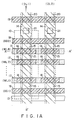
- Figs. 1A to 1C show the structure of the memory array of a conventional NAND type EEPROM suitable for large scale integration.
- Fig. 1A is a plane view of the pattern.
- Fig. 1B is a cross section along line A-A' of Fig. 1A
- Fig. 1C is a cross section along line B-B' of Fig. 1A.
- a portion enclosed by a broken line and indicated at 10 represents one NAND basic block.
- this NAND basic block 10 is partitioned from other NAND basic blocks disposed in the right/left direction as viewed in Fig. 1B by field oxide films 12, 12, ...
- the vertical cross section of the NAND basic block 10 is as shown in Fig.
- reference numeral 11 represents a p-type silicon semiconductor substrate, 13 a common source region made of an n + diffusion layer and shared by respective basic blocks 10, 14 a drain region of the NAND basic block 10 which region is also made of an n + diffusion layer, 15, 15, ... source/drain regions of memory cells within the NAND basic block 10 which regions are made of n + diffusion layers, 16, 16, ... floating gates made of a first polysilicon, 17, 17, ...
- ONO oxide-nitride-oxide
- This gate oxide film 25 may be of the ONO three-layered structure which is formed at the time of forming the gate oxide film 23.
- the select gate transistors 18 and 19 are made of only the second polysilicon layer without using the first polysilicon layer.
- each NAND basic block 10 is formed with ten transistors (memory cells and select gate transistors) 31 to 40 which will be described later in detail.
- the transistors 31 to 40 are turned on and off by means of gates 17 to 19 of respective channels.
- the on/off of the transistors 32 to 39 is controlled in dependence upon whether each floating gate 16 has electrons or holes.
- Each floating gate 16 stores “1” or "0” in dependence on whether it has electrons or holes.
- the number of control gates 17, 17, ... provided for each NAND basic block 10 is, for example, eight.
- Each control gate is formed continuously to cover a plurality of floating gates 16, 16, ... positioned under the control gate. Namely, as seen from Figs. 1A and 1B in particular, the width (width in the up/down direction as viewed in Fig. 1A) of each floating gate 16, 16, ... is the same as that of each control gate 17, 17, ..., and the length (length in the right/left direction as viewed in Fig. 1A) of each floating gate 16, 16, ... is formed shorter than the width of each NAND basic block.
- the memory cell array is constructed by disposing the NAND basic blocks 10 in matrix in the up/down right/left directions as viewed in Fig. 1A.
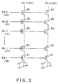
- the equivalent circuit of the NAND basic block 10 is shown in Fig. 2.
- Fig. 2 two NAND basic blocks 10 and 10 disposed right and left are shown.
- the equivalent circuit of each NAND basic block 10 is constructed such that between the source 13 and the data line 20 (DL1, DL2), the select gate transistor 31, eight memory cells 32 to 39, and select gate transistor 40 are serially connected.
- the transistors 31 and 40 are inputted with select gate signals SG1 and SG2, respectively, and word lines WL1 to WL8 are connected to the control gates 17 of the memory cells 32 to 39.
- data are erased by applying a high voltage, e.g., 15 V to the control gate 17 and connecting the source 15 and drain 15 to a 0 V ground potential.
- a high voltage e.g. 15 V
- the control gate 17 and the floating gate 16 are electrostatically coupled so that the potential of the floating gate 16 rises and electrons are injected from the source 15 or drain 15 into the floating gate 16 via the gate oxide film 22.
- This is called an erase state, and the stored data at this state is defined as a "1" level.
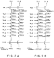
- the threshold voltage of the memory cell at this state becomes about 2 to 3 V as shown in the characteristic curves of Fig. 4.
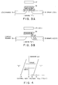
- Fig. 3B data are written by setting the control gate 17 at 0 V, making the source 15 in an open state, and applying a high voltage to the drain 15. In this case, electrons are emitted to the drain 15 from the floating gate 16, and the threshold voltage of the memory cell becomes about -5 V as shown in the characteristic curves of Fig. 4. the stored data at this state are defined as a "0" level.
- Data are erased by setting the data line DL1, DL2 to 0 V, SG1 to 5 V, SG2 to 15 V, and word lines WL1 to WL8 to 15 V. In this state, all the drains and sources of the memory cells 32 to 39 become 0 V so that all the data in the memory cells 32 to 29 are erased collectively.
- Data are written sequentially and selectively starting from the memory cell 32 (cell 1) nearest to the select gate transistor 31.
- SG1 is set to 0 V
- word line WL1 is set to 0 V
- all the other word lines WL2 to WL8 to 20 V so that the memory cell 32 is selected and data are written therein.
- the threshold voltage of the memory cell whose data have been erased is about 3 V, whereas that of the memory cells 33 to 39 (cell 2 to cell 8) with a high voltage being applied in a write state is about 5 V while taking the substrate effect into consideration.
- word lines WL1 and WL2 are set to 0 V, and all the other word lines WL3 to WL8 are set to 20 V.
- data writing is sequentially performed up to the memory cell 39 with voltages being set as shown in Table 1.
- data line DL1 is applied with 0 V or 10 V instead of 20 V. In this case, a voltage is not applied between the floating gate and the drain, or an applied voltage is small, so that data are not written.
- data writing is sequentially performed for eight memory cells starting from the memory cell 32 on the source side.
- the reason for this is that if data are written into a cell without using this data writing order, a high voltage (20 V) is applied to the word lines of the other cells already written, and 0 V is applied to the drain, to thereby produce an erase state and erase the date in the other cells.
- a high voltage (20 V) is applied to the word lines of the other cells already written, and 0 V is applied to the drain, to thereby produce an erase state and erase the date in the other cells.
- the other data line DL2 is applied with about 10 V which is an intermediate voltage between the write and erase operations. This is carried out for preventing erroneous data erase/write relative to the memory cells connected on the data line DL2.
- SG2 is set to 0 V and the word lines WL1 to WL8 are set to 0 V so as to prevent erroneous data erase/write.
- the data read operation from the NAND basic block is carried out in the following manner.
- Fig. 2 consider the case wherein data are read by selecting the memory cell 32 in the NAND basic block connected to the data lines DL1.
- DL1 is set to 1 V, SG1 and SG2 to 5 V, the selected word line WL1 to 0 V, and the other word lines WL2 to WL8 to 5 V.
- the non-selected data line DL2 becomes a floating state, and takes approximately 0 V. If the stored data in the selected memory cell 32 are of the "1" level (threshold voltage of +3 V), the control gate voltage is 0 V so that it takes an off-state.
- the selected NAND basic block 10 current will not flow between the data line DL1 and the ground potential so that the "1" level data are sensed with a sense amplifier (not shown) connected to the data line DL1.
- the stored data in the selected memory cell 32 is of "0" level (threshold voltage of -5 V)
- the memory cell 32 takes an on-state even if the control gate voltage is 0 V.
- the control gate voltages of the other memory cells 33 to 39 are 5 V and these memory cells 33 to 39 take an on-state irrespective of the stored data. Therefore, in this basic block, current flows between the data line DL1 and the ground potential so that the "0" level data are sensed with the sense amplifier.
- memory cells can be disposed at the pitch of the word lines (control gates 17), and only a single contact 21 is used for a plurality (e.g., eight) of memory cells, allowing a larger number of memory cells per unit area and providing a structure suitable for miniaturizing a large capacity memory.
- Such a conventional memory has the following problems.
- a first problem is as follows. Since a NAND basic block has a NAND type cell structure with a plurality of memory cells connected in series, it is necessary for reading data from a selected memory cell to turn on other non-selected and erased memory cells. It becomes necessary to therefore turn them on by using a 5 V gate voltage and to maintain the threshold voltage smaller than or equal to about 3 V (at least smaller than or equal to 5 V). Similarly, it is also necessary to maintain the threshold voltage of the selected and erased memory cell larger than or equal to about 1 V (at least larger than or equal to 0 V). It is difficult however, to uniformly erase all memory cells of a large capacity memory of large scale such as 1 M bits or 4 M bits as variation will necessarily occur. If such variation causes the threshold voltage of even one erased memory cell to move out of the range from 0 V to 3 V, then the memory becomes a defective one. It is very difficult to design and manufacture a memory capable of uniformly and reliably erase the data of all memory cells.
- a NAND basic block which includes a memory cell storing "0" level data. Also in this case, if the threshold voltage of a non-selected memory cell whose gate is applied with 5 V, is 3 V, it is not possible to make an on-current sufficiently large. For instance, in a NAND basic block designed on the basis of a 1 ⁇ m rule, a cell current only in the order of several ⁇ A flows during data reading, which is not suitable from the standpoint of increased speed.
- a second problem of such a conventional memory is the necessity of high voltage withstanding.
- the threshold voltage of the memory cells 33 to 39 is about 5 V so that a high voltage of 20 V becomes necessary to efficiently write data in the memory cell 32.
- a sufficiently high voltage withstand is required for peripheral circuits, while posing another problem of lowering the reliability due to voltage stress applied to memory cells.
- the JP-A-62 54962 discloses a transistor comprising one conductive type semiconductor substrate, a source region and a drain region having a conductive type reversed to said semiconductor substrate provided on said semiconductor substrate, a gate insulting film provided on a channel region between said source region and said drain region, a floating gate electrode which extends over and between said source region and said drain region and which is provided so as to cover a part of said gate insulating film, and a control gate electrode provided on said floating gate electrode and said channel region not covered with said floating gate electrode through an insulating film, wherein said floating gate electrode is provide so that a threshold voltage of said channel region not covered with said floating gate electrode and having no memory function is higher than a threshold voltage after writing a low level of said channel region covered with said floating gate electrode and having a memory function but lower than a threshold voltage after writing a high level.
- the threshold voltage after writing in the whole transistor does not exceed 1 V irrespective of the amount of electrons injected into the floating gate electrode. That is, the threshold voltage after writing is determined by the control of the threshold voltage of the channel region having no memory function under the control gate electrode instead of the amount of electrons injected into the floating gate electrode.
- the transistor structure disclosed in the JP-A-62 549 62 may be affected by mask alignment if used in a plurality of basic blocks of non-volatile semiconductor each having a plurality of those transistors connected in series.
- the JP-A-58 190069 discloses a non-volatile memory device comprising a semiconductor substrate, drain and source regions formed at required intervals on said semiconductor substrate, a floating gate on the region sandwiched between said drain and source regions, at least one side thereof being formed within the width of each region through an insulating layer so as to extend over the regions, and a control gate, or said floating gate, formed through an insulating layer so as to extend over the regions in the region sandwiched between said drain and source regions, wherein a thickness of an insulating corresponding portion between the control gate and the substrate at a portion where only the control gate is present is made larger than a thickness of an insulating layer corresponding portion between the floating gate and the substrate at a portion where said control gate and said floating gate are present.
- the width of the floating gate is smaller than that between source and drain, the presence of the transistor between source and drain where no floating gate is present, need not to be taken into account at the time of readout, whereas at the time of writing all transistor between source and drain are turned on.
- Figs. 5A and 5B shown the memory array of a NAND type EEPROM leading to the present invention, wherein Fig. 5A is a plan view of the pattern, and Fig. 5B is a cross section along line A-A' of Fig. 5A.
- Figs. 5A and 5B similar constitutional elements to those shown in Figs. 1A to 5B are represented by using identical reference numerals shown in Figs. 1A to 1C.
- the device shown Figs. 5A and 5B is applied with the same voltages shown in Table 1 (although a write voltage value is small and an erase voltage value is large) to perform erase, write and read operations.
- each floating gate 16 is displaced left in the extending direction of a control gate 17. With such displacement arrangement, each floating gate 16 covers not all the area of each memory cell (32 to 39) but a partial area thereof.
- the floating gate 16 overlaps the control gate 17 to form a floating gate transistor (39a), whereas at the remaining area, only the control gate 17 is present to form an enhancement type transistor (39b).
- Each memory cell is therefore constructed of a parallel connection of the above-described two types of transistors.
- the equivalent circuit of each NAND basic block 10 shown in Fig. 5A is therefore represented as shown in Fig. 6.
- the curve (b) shown in Fig. 7 indicates the characteristic of a memory cell in an erase state.
- the threshold voltage of a floating transistor e.g., transistor 32a shown in Fig. 6
- the threshold voltage of the enhancement type transistor 32b connected in parallel with the transistor 32a is 1 V as seen from the curve (b).
- the characteristic of the enhancement type transistor 32b becomes dominant as the characteristic of the memory cell 32, thus presenting the threshold voltage of 1 V.
- the enhancement type transistors 33b to 39b become dominant.
- the curve (c) shown in Fig. 7 represents the characteristic of a memory cell in a write state.
- the threshold voltage becomes about -5 V.
- the threshold voltage of an enhancement type transistor (e.g., 32b) in the write state remains 1 V which is the same as the case of the erase state
- the threshold voltage of a floating gate transistor (e.g., 32a) becomes about -5 V.
- the characteristic of a floating gate transistor becomes dominant as the characteristic of the memory cell, thereby presenting the threshold voltage of about -5 V.
- the threshold voltage in the erase state is determined by the enhancement type transistor. It is easy to design and manufacture enhancement type transistors having a threshold voltage of 1 V.
- the threshold voltage of floating gate transistors may take any value larger than or equal to 1 V (at least larger than or equal to 0 V), so that if data are erased sufficiently while considering threshold voltage variation, a large cell current can flow to thereby realize a stable characteristic.
- the erase, write and read operations of the NAND basic block is the same as that described with Table 1. It is necessary for a conventional memory to set the threshold voltage within the range from 1 V to 3 V in the erase state. Therefore, too high a voltage cannot be applied to the word line. For this reason, a relatively low voltage 15 V is applied to slowly erase data and carefully move to a desired threshold voltage.
- the threshold voltage in the erase state is determined by the enhancement type transistor so that it is not necessary to consider to what degree the threshold voltage of the floating gate transistor moves in the erase state. A voltage higher than convention, e.g. in the order of 17 V can therefore be applied to the word line to sufficiently erase data.
- the threshold voltage of an erased memory cell rises to about 5 V to that it is necessary to apply a high voltage 20 V to the control gate of a non-selected memory cell in order to apply 15 V to the drain of a selected memory cell.
- the threshold voltage in the erase state is as low as 1 V, or about 2 V if the substrate effect is considered, so that a voltage about 17 V lower than conventionally applied, can be applied to the control gate of a non-selected memory cell in order to obtain a voltage 15 V as conventionally obtained at the drain of a selected memory cell.
- Fig. 8 is a plan view of the pattern according to the first embodiment according to this invention.
- similar constitutional elements to those shown in Fig. 5A are represented by identical reference numerals.
- the different point of the embodiment shown in Fig. 8 from that shown in Fig. 5A is that each floating gate 16 is displaced right or left (in the extension direction of control gate 17) to be disposed in a so-called staggered arrangement. Namely, the positions of the floating gates 16 are alternately displaced for each word line and for each data line. With this arrangement, a large margin of displacement in mask alignment during manufacturing processes can be obtained. This will be explained while comparing with the case where the positions of the floating gates 16 are not displaced right or left as shown in Fig. 5A. In Fig.
- the transistor 32a in the on-state has a threshold voltage sufficiently negative so that it allows a sufficient current to flow as compared to the transistors 33b to 39b . Accordingly, assuming that the floating gates 16 displace to the right due to mask displacement, the enhancement type transistors 32b to 39b all allow a small current to flow as shown in Fig. 9A. If a memory is formed in such a manufacturing condition, the speed is lowered and in some cases the manufactured memory becomes a faulty one.
- the floating gates are displaced alternately for each word line. It is not necessary to use such an arrangement by all means.
- the displacement direction of the floating gate may be changed collectively for word lines WL1 to WL4 and word lines WL5 to WL8. By collectively displacing as above, the manufacturing technique becomes simple. It is also unnecessary that the same number of floating gates be displaced for each direction.
- the operation has been described with the definition that electrons are injected on the floating gate for the erase operation, and electrons withdrawn therefrom for the write operation.
- the operation may be described with the opposite definition that electrons are injected into the floating gate for the write operation, and electrons are withdrawn therefrom for the erase operation.
- all memory cells are collectively erased in the above embodiments, they may be erased for each word line by selectively applying a voltage to a word line during the erase operation.
- the invention is not limited tot he above embodiments, but various modifications may be possible which do not contradict the gist of this invention.
- an independent E type transistor is provided in parallel with a conventional floating gate transistor, with the arrangement that the control gate is used commonly and the channel portion is separately formed.
- a floating type non-volatile memory has been described, the gist of the present invention is not limited thereto, but a memory cell of a so-called MNOS (Metal-Nitride-Oxide-Semiconductor) type where electric charges are charged at the trap level is also included in this invention.
- MNOS Metal-Nitride-Oxide-Semiconductor
Claims (5)
- Mémoire rémanente à semi-conducteur comprenant :une pluralité de blocs (10) de base ayant chacun une pluralité de cellules de mémoire (32-39) rémanente agencées et connectées en série ;lesdites cellules de mémoire (32-39) ayant une paire de régions (13, 14, 15) de source et de drain chacune formée sur la superficie d'un substrat (11) semi-conducteur et entre lesquelles sont intercalées une région de canal, une grille (16) flottante formée au-dessus de ladite région de canal et capable de charger des charges électriques, et une grille (17) de commande formée au-dessus de ladite grille (16) flottante et de ladite région de canal ;ladite grille (16) flottante recouvrant une partie de ladite région de canal de façon qu'un transistor (39a) à grille flottante soit formé de telle manière que ladite grille (16) flottante et ladite grille (17) de commande soient disposées au-dessus de ladite région de canal, et qu'un transistor (39b) du type à enrichissement soit formé de telle manière que seule ladite grille (17) de commande soit disposée au-dessus de ladite région de canal, ledit transistor du type à enrichissement étant placé de façon adjacente au transistor à grille flottante dans la direction de l'étendue de ladite grille (17) de commande et ledit transistor (39a) à grille flottante et ledit transistor (39b) du type à enrichissement étant électriquement connectés l'un à l'autre en parallèle ; etla tension de seuil dudit transistor (39a) à grille flottante détermine la caractéristique de ladite cellule de mémoire dans l'un ou l'autre des états d'effacement ou d'écriture, tandis que la tension de seuil dudit transistor (39b) du type à enrichissement détermine la caractéristique de ladite cellule de mémoire dans l'autre desdits états ;
caractérisé en ce quepour au moins l'une desdites cellules de mémoire (32 - 39), ladite grille (16) flottante est déplacée dans la direction de l'étendue de ladite grille (17) de commande afin de recouvrir partiellement ladite région de canal sensiblement du centre de ladite région de canal à l'une des frontières de la région de canal dans la direction de l'étendue de ladite grille (17) de commande, et en ce que pour au moins une autre desdites cellules de mémoire (32 - 39), ladite grille (16) flottante est déplacée dans la direction de l'étendue de ladite grille (17) de commande pour recouvrir partiellement ladite région de canal sensiblement du centre de ladite région de canal à l'autre des frontières de la région de canal dans la direction de l'étendue de ladite grille (17) de commande. - Mémoire selon la revendication 1, dans laquelle ladite pluralité de cellules de mémoire (32 - 39) dans ledit bloc (10) de base sont divisées en une pluralité de groupes de cellules comprenant chacun un nombre choisi de cellules de mémoire (32 - 39), les grilles (16) flottantes de cellules de mémoire (32 - 39) appartenant au même groupe de cellules sont déplacées dans la même direction, et certains des groupes de cellules de ladite pluralité de groupes de cellules sont déplacés dans une direction opposée à celle de l'autre des groupes de cellules de ladite pluralité de groupes de cellules.
- Mémoire selon la revendication 2, dans laquelle ledit nombre choisi est égal à un.
- Mémoire selon la revendication 2, dans laquelle ledit nombre choisi est égal à deux ou plus.
- Procédé de mise en fonctionnement d'une mémoire selon l'une quelconque des revendications précédentes, comprenant les étapes de mise de ladite paire de régions de source (13) et de drain (14) du bloc (10) de base et/ou dudit substrat (11) à un potentiel plus élevé que celui de ladite grille (17) de commande de chacune desdites cellules de mémoire (32 - 39), de façon que des électrons se trouvant dans ladite grille flottante (16) soient déchargés dans lesdites régions de source (13) et de drain (14) du bloc de base et/ou dudit substrat (11) ;de mise de ladite grille de commande a un potentiel plus élevé que celui de ladite paire de régions de source (13) et de drain (14) du bloc (10) de base et/ou dudit substrat (11) de façon que des électrons provenant desdites régions de source (13) et de drain (14) du bloc (10) de base et/ou dudit substrat (11) soient injectés dans ladite grille (16) flottante.
Applications Claiming Priority (7)
| Application Number | Priority Date | Filing Date | Title |
|---|---|---|---|
| JP265370/88 | 1988-10-21 | ||
| JP63265370A JPH07105451B2 (ja) | 1988-10-21 | 1988-10-21 | 不揮発性半導体メモリ |
| JP26537088 | 1988-10-21 | ||
| JP22400689 | 1989-08-30 | ||
| JP224006/89 | 1989-08-30 | ||
| JP1224006A JPH0770627B2 (ja) | 1989-08-30 | 1989-08-30 | 不揮発性半導体メモリ |
| EP89910179A EP0419663B1 (fr) | 1988-10-21 | 1989-09-14 | Memoire a semi-conducteur remanente et procede de production |
Related Parent Applications (2)
| Application Number | Title | Priority Date | Filing Date |
|---|---|---|---|
| EP89910179A Division EP0419663B1 (fr) | 1988-10-21 | 1989-09-14 | Memoire a semi-conducteur remanente et procede de production |
| EP89910179.4 Division | 1989-09-14 |
Publications (2)
| Publication Number | Publication Date |
|---|---|
| EP0639860A1 EP0639860A1 (fr) | 1995-02-22 |
| EP0639860B1 true EP0639860B1 (fr) | 2000-06-28 |
Family
ID=26525796
Family Applications (2)
| Application Number | Title | Priority Date | Filing Date |
|---|---|---|---|
| EP89910179A Expired - Lifetime EP0419663B1 (fr) | 1988-10-21 | 1989-09-14 | Memoire a semi-conducteur remanente et procede de production |
| EP94115451A Expired - Lifetime EP0639860B1 (fr) | 1988-10-21 | 1989-09-14 | Mémoire semi-conductrice rémanente |
Family Applications Before (1)
| Application Number | Title | Priority Date | Filing Date |
|---|---|---|---|
| EP89910179A Expired - Lifetime EP0419663B1 (fr) | 1988-10-21 | 1989-09-14 | Memoire a semi-conducteur remanente et procede de production |
Country Status (5)
| Country | Link |
|---|---|
| US (3) | US5323039A (fr) |
| EP (2) | EP0419663B1 (fr) |
| KR (1) | KR940008228B1 (fr) |
| DE (2) | DE68929225T2 (fr) |
| WO (1) | WO1990004855A1 (fr) |
Families Citing this family (42)
| Publication number | Priority date | Publication date | Assignee | Title |
|---|---|---|---|---|
| WO1993011509A1 (fr) * | 1991-12-04 | 1993-06-10 | Citizen Watch Co., Ltd. | Support de donnees |
| JP2959066B2 (ja) * | 1990-07-11 | 1999-10-06 | 日本電気株式会社 | 不揮発性半導体記憶装置およびその駆動方法 |
| US5291440A (en) * | 1990-07-30 | 1994-03-01 | Nec Corporation | Non-volatile programmable read only memory device having a plurality of memory cells each implemented by a memory transistor and a switching transistor stacked thereon |
| DE4026408A1 (de) * | 1990-08-21 | 1992-02-27 | Philips Patentverwaltung | Elektrisch programmier- und loeschbarer halbleiterspeicher und verfahren zu seinem betrieb |
| DE4026409A1 (de) * | 1990-08-21 | 1992-02-27 | Philips Patentverwaltung | Elektrisch programmier- und loeschbarer halbleiterspeicher und verfahren zu seinem betrieb |
| US5321286A (en) * | 1991-11-26 | 1994-06-14 | Nec Corporation | Non-volatile semiconductor memory device having thin film memory transistors stacked over associated selecting transistors |
| FR2693308B1 (fr) * | 1992-07-03 | 1994-08-05 | Commissariat Energie Atomique | Memoire eeprom a triples grilles et son procede de fabrication. |
| US5350706A (en) * | 1992-09-30 | 1994-09-27 | Texas Instruments Incorporated | CMOS memory cell array |
| KR950013342B1 (ko) * | 1992-10-06 | 1995-11-02 | 삼성전자주식회사 | 반도체 메모리장치의 결함구제회로 |
| KR960006748B1 (ko) * | 1993-03-31 | 1996-05-23 | 삼성전자주식회사 | 고속동작 및 저전원공급전압에 적합한 쎌구조를 가지는 불휘발성 반도체 집적회로 |
| JP2825407B2 (ja) * | 1993-04-01 | 1998-11-18 | 株式会社東芝 | 不揮発性半導体記憶装置 |
| JP3450467B2 (ja) * | 1993-12-27 | 2003-09-22 | 株式会社東芝 | 不揮発性半導体記憶装置及びその製造方法 |
| DE69527734T2 (de) * | 1994-03-11 | 2003-05-15 | St Microelectronics Inc | Flash EEPROM und EPROM-Anordnungen |
| JP3469362B2 (ja) * | 1994-08-31 | 2003-11-25 | 株式会社東芝 | 半導体記憶装置 |
| EP0752721B1 (fr) * | 1995-06-29 | 2009-04-29 | Sharp Kabushiki Kaisha | Mémoire semi-conductrice non-volatile et méthode de commande et procédé de fabrication |
| US5877054A (en) * | 1995-06-29 | 1999-03-02 | Sharp Kabushiki Kaisha | Method of making nonvolatile semiconductor memory |
| JP3366173B2 (ja) * | 1995-07-31 | 2003-01-14 | シャープ株式会社 | 不揮発性半導体メモリの製造方法 |
| US5844271A (en) * | 1995-08-21 | 1998-12-01 | Cypress Semiconductor Corp. | Single layer polycrystalline silicon split-gate EEPROM cell having a buried control gate |
| KR0179791B1 (ko) * | 1995-12-27 | 1999-03-20 | 문정환 | 플래쉬 메모리 소자 및 그 제조방법 |
| DE69630107D1 (de) * | 1996-04-15 | 2003-10-30 | St Microelectronics Srl | Mit einem EEPROM integrierter FLASH-EPROM |
| US5741737A (en) | 1996-06-27 | 1998-04-21 | Cypress Semiconductor Corporation | MOS transistor with ramped gate oxide thickness and method for making same |
| US5897354A (en) * | 1996-12-17 | 1999-04-27 | Cypress Semiconductor Corporation | Method of forming a non-volatile memory device with ramped tunnel dielectric layer |
| US6781883B1 (en) * | 1997-03-20 | 2004-08-24 | Altera Corporation | Apparatus and method for margin testing single polysilicon EEPROM cells |
| JP3586072B2 (ja) * | 1997-07-10 | 2004-11-10 | 株式会社東芝 | 不揮発性半導体記憶装置 |
| US6023085A (en) * | 1997-12-18 | 2000-02-08 | Advanced Micro Devices, Inc. | Core cell structure and corresponding process for NAND-type high performance flash memory device |
| FR2783972B1 (fr) * | 1998-09-29 | 2003-05-30 | Commissariat Energie Atomique | Cellule memoire non volatile, auto-alignee, sans contact et a surface reduite |
| EP0993036A1 (fr) * | 1998-10-09 | 2000-04-12 | STMicroelectronics S.r.l. | Méthode de fabrication d'un dispositif semi-conducteur intégré comprenant un transistor à effet de champ à grille flottante et un transistor logique à effet de champ, et ispositif correspondant |
| US6235586B1 (en) * | 1999-07-13 | 2001-05-22 | Advanced Micro Devices, Inc. | Thin floating gate and conductive select gate in situ doped amorphous silicon material for NAND type flash memory device applications |
| KR100346598B1 (ko) | 1999-10-07 | 2002-07-26 | 동부전자 주식회사 | 반도체 디바이스의 메모리 셀 제조 방법 |
| JP2002289705A (ja) * | 2001-03-23 | 2002-10-04 | Fujitsu Ltd | 半導体メモリ |
| KR100395755B1 (ko) * | 2001-06-28 | 2003-08-21 | 삼성전자주식회사 | 비휘발성 메모리 소자 및 그 제조방법 |
| JP2003163292A (ja) * | 2001-08-13 | 2003-06-06 | Halo Lsi Inc | ツインnand素子構造、そのアレイ動作およびその製造方法 |
| US6989551B2 (en) * | 2001-11-02 | 2006-01-24 | Lattice Semiconductor Corporation | Test structure for determining a minimum tunnel opening size in a non-volatile memory |
| US7326994B2 (en) * | 2005-10-12 | 2008-02-05 | Taiwan Semiconductor Manufacturing Company, Ltd. | Logic compatible non-volatile memory cell |
| KR100829604B1 (ko) * | 2006-09-26 | 2008-05-14 | 삼성전자주식회사 | 불휘발성 메모리 장치 및 그 제조 방법 |
| US7663916B2 (en) | 2007-04-16 | 2010-02-16 | Taiwan Semicondcutor Manufacturing Company, Ltd. | Logic compatible arrays and operations |
| DE102007028179A1 (de) | 2007-06-20 | 2008-12-24 | Christian Großekathöfer | Frei gestaltbarer Datenträger (für Film, Musik & Multimediadaten) |
| US7968926B2 (en) | 2007-12-19 | 2011-06-28 | Taiwan Semiconductor Manufacturing Company, Ltd. | Logic non-volatile memory cell with improved data retention ability |
| US8174071B2 (en) * | 2008-05-02 | 2012-05-08 | Taiwan Semiconductor Manufacturing Co., Ltd. | High voltage LDMOS transistor |
| KR102002942B1 (ko) * | 2013-04-18 | 2019-07-24 | 에스케이하이닉스 주식회사 | 비휘발성 메모리 장치 및 그 제조방법 |
| TWI555213B (zh) * | 2014-09-04 | 2016-10-21 | 力晶科技股份有限公司 | 快閃記憶體閘極結構及其製作方法 |
| US11322516B2 (en) | 2020-08-31 | 2022-05-03 | Micron Technology, Inc. | Microelectronic devices including isolation structures protruding into upper pillar portions, and related methods and systems |
Family Cites Families (11)
| Publication number | Priority date | Publication date | Assignee | Title |
|---|---|---|---|---|
| JPS57162370A (en) * | 1981-03-30 | 1982-10-06 | Seiko Epson Corp | Mos semiconductor memory device |
| JPS58190069A (ja) * | 1982-04-29 | 1983-11-05 | Mitsubishi Electric Corp | 半導体不揮発性メモリ装置 |
| JPS5955071A (ja) * | 1982-09-24 | 1984-03-29 | Hitachi Micro Comput Eng Ltd | 不揮発性半導体装置 |
| US4635347A (en) * | 1985-03-29 | 1987-01-13 | Advanced Micro Devices, Inc. | Method of fabricating titanium silicide gate electrodes and interconnections |
| JPS6254962A (ja) * | 1985-09-04 | 1987-03-10 | Nec Corp | トランジスタ |
| US5050125A (en) * | 1987-11-18 | 1991-09-17 | Kabushiki Kaisha Toshiba | Electrically erasable programmable read-only memory with NAND cellstructure |
| US5017980A (en) * | 1988-07-15 | 1991-05-21 | Texas Instruments Incorporated | Electrically-erasable, electrically-programmable read-only memory cell |
| KR910004166B1 (ko) * | 1988-12-27 | 1991-06-22 | 삼성전자주식회사 | 낸드쎌들을 가지는 전기적으로 소거 및 프로그램 가능한 반도체 메모리장치 |
| KR940006094B1 (ko) * | 1989-08-17 | 1994-07-06 | 삼성전자 주식회사 | 불휘발성 반도체 기억장치 및 그 제조방법 |
| JPH04212472A (ja) * | 1990-07-13 | 1992-08-04 | Toshiba Corp | 不揮発性半導体記憶装置の製造方法 |
| JPH06254962A (ja) * | 1993-03-05 | 1994-09-13 | Canon Aptecs Kk | ラミネート装置 |
-
1989
- 1989-09-14 WO PCT/JP1989/000942 patent/WO1990004855A1/fr active IP Right Grant
- 1989-09-14 US US07/499,342 patent/US5323039A/en not_active Expired - Lifetime
- 1989-09-14 EP EP89910179A patent/EP0419663B1/fr not_active Expired - Lifetime
- 1989-09-14 EP EP94115451A patent/EP0639860B1/fr not_active Expired - Lifetime
- 1989-09-14 DE DE68929225T patent/DE68929225T2/de not_active Expired - Fee Related
- 1989-09-14 DE DE68924849T patent/DE68924849T2/de not_active Expired - Fee Related
- 1989-09-14 KR KR1019900701347A patent/KR940008228B1/ko not_active IP Right Cessation
-
1994
- 1994-05-23 US US08/247,589 patent/US5597748A/en not_active Expired - Lifetime
-
1997
- 1997-10-14 US US08/949,819 patent/US5824583A/en not_active Expired - Fee Related
Also Published As
| Publication number | Publication date |
|---|---|
| EP0419663A1 (fr) | 1991-04-03 |
| KR900702578A (ko) | 1990-12-07 |
| DE68924849T2 (de) | 1996-06-13 |
| EP0419663B1 (fr) | 1995-11-15 |
| EP0419663A4 (en) | 1991-06-12 |
| WO1990004855A1 (fr) | 1990-05-03 |
| US5323039A (en) | 1994-06-21 |
| DE68929225T2 (de) | 2000-11-30 |
| US5597748A (en) | 1997-01-28 |
| DE68929225D1 (de) | 2000-08-03 |
| DE68924849D1 (de) | 1995-12-21 |
| KR940008228B1 (ko) | 1994-09-08 |
| EP0639860A1 (fr) | 1995-02-22 |
| US5824583A (en) | 1998-10-20 |
Similar Documents
| Publication | Publication Date | Title |
|---|---|---|
| EP0639860B1 (fr) | Mémoire semi-conductrice rémanente | |
| US5568421A (en) | Semiconductor memory device on which selective transistors are connected to a plurality of respective memory cell units | |
| KR100206709B1 (ko) | 멀티비트 불휘발성 반도체 메모리의 셀 어레이의 구조 및 그의 구동방법 | |
| US5422844A (en) | Memory array with field oxide islands eliminated and method | |
| US6191975B1 (en) | Non-volatile NAND type semiconductor memory device with stacked gate memory cells and a stacked gate select transistor | |
| US7333367B2 (en) | Flash memory devices including multiple dummy cell array regions | |
| KR100187196B1 (ko) | 불휘발성 반도체 메모리 장치 | |
| EP1256960B1 (fr) | Procédé de programmation d'une mémoire semi-conductrice | |
| US6731539B1 (en) | Memory with offset bank select cells at opposite ends of buried diffusion lines | |
| EP1020925B1 (fr) | Dispositif semi-conducteur de mémoire et méthode pour le commander | |
| KR960016106B1 (ko) | 비 휘발성 반도체 메모리 장치 | |
| US20030002343A1 (en) | Programming method for non-volatile semiconductor memory device | |
| US5179427A (en) | Non-volatile semiconductor memory device with voltage stabilizing electrode | |
| EP0833345A2 (fr) | Dispositif de mémoire à semi-conducteur non volatile | |
| US7486533B2 (en) | Nonvolatile semiconductor memory | |
| US5177705A (en) | Programming of an electrically-erasable, electrically-programmable, read-only memory array | |
| US5394357A (en) | Non-volatile semiconductor memory device | |
| JP2960082B2 (ja) | 不揮発性半導体メモリ | |
| KR100330681B1 (ko) | 반도체 기억 장치 | |
| US20010001492A1 (en) | Nonvolatile semiconductor memory device structure with superimposed bit lines and short-circuit metal strips | |
| JPH065873A (ja) | 不揮発性半導体記憶装置 | |
| JP2725086B2 (ja) | 不揮発性半導体記憶装置の消去方法 | |
| JPH0770627B2 (ja) | 不揮発性半導体メモリ | |
| JPH07105451B2 (ja) | 不揮発性半導体メモリ | |
| JP2001015615A (ja) | 不揮発性半導体記憶装置 |
Legal Events
| Date | Code | Title | Description |
|---|---|---|---|
| PUAI | Public reference made under article 153(3) epc to a published international application that has entered the european phase |
Free format text: ORIGINAL CODE: 0009012 |
|
| 17P | Request for examination filed |
Effective date: 19940930 |
|
| AC | Divisional application: reference to earlier application |
Ref document number: 419663 Country of ref document: EP |
|
| AK | Designated contracting states |
Kind code of ref document: A1 Designated state(s): DE FR GB |
|
| RIN1 | Information on inventor provided before grant (corrected) |
Inventor name: MASUOKA, FUJIO Inventor name: ENDOH, TETSUO Inventor name: SHIROTA, RIICHIRO Inventor name: INOUE, SATOSHI Inventor name: NAKAYAMA, RYOZO Inventor name: KIRISAWA, RYOUHEI Inventor name: IWAHASHI, HIROSHI Inventor name: ASANO, MASAMICHI |
|
| GRAG | Despatch of communication of intention to grant |
Free format text: ORIGINAL CODE: EPIDOS AGRA |
|
| 17Q | First examination report despatched |
Effective date: 19980122 |
|
| GRAG | Despatch of communication of intention to grant |
Free format text: ORIGINAL CODE: EPIDOS AGRA |
|
| GRAG | Despatch of communication of intention to grant |
Free format text: ORIGINAL CODE: EPIDOS AGRA |
|
| GRAH | Despatch of communication of intention to grant a patent |
Free format text: ORIGINAL CODE: EPIDOS IGRA |
|
| GRAH | Despatch of communication of intention to grant a patent |
Free format text: ORIGINAL CODE: EPIDOS IGRA |
|
| GRAA | (expected) grant |
Free format text: ORIGINAL CODE: 0009210 |
|
| AC | Divisional application: reference to earlier application |
Ref document number: 419663 Country of ref document: EP |
|
| AK | Designated contracting states |
Kind code of ref document: B1 Designated state(s): DE FR GB |
|
| PG25 | Lapsed in a contracting state [announced via postgrant information from national office to epo] |
Ref country code: FR Free format text: LAPSE BECAUSE OF FAILURE TO SUBMIT A TRANSLATION OF THE DESCRIPTION OR TO PAY THE FEE WITHIN THE PRESCRIBED TIME-LIMIT Effective date: 20000628 |
|
| REF | Corresponds to: |
Ref document number: 68929225 Country of ref document: DE Date of ref document: 20000803 |
|
| EN | Fr: translation not filed | ||
| PLBE | No opposition filed within time limit |
Free format text: ORIGINAL CODE: 0009261 |
|
| STAA | Information on the status of an ep patent application or granted ep patent |
Free format text: STATUS: NO OPPOSITION FILED WITHIN TIME LIMIT |
|
| 26N | No opposition filed | ||
| PGFP | Annual fee paid to national office [announced via postgrant information from national office to epo] |
Ref country code: FR Payment date: 20010911 Year of fee payment: 13 |
|
| REG | Reference to a national code |
Ref country code: GB Ref legal event code: IF02 |
|
| PGFP | Annual fee paid to national office [announced via postgrant information from national office to epo] |
Ref country code: DE Payment date: 20070906 Year of fee payment: 19 |
|
| PGFP | Annual fee paid to national office [announced via postgrant information from national office to epo] |
Ref country code: GB Payment date: 20070912 Year of fee payment: 19 |
|
| GBPC | Gb: european patent ceased through non-payment of renewal fee |
Effective date: 20080914 |
|
| PG25 | Lapsed in a contracting state [announced via postgrant information from national office to epo] |
Ref country code: DE Free format text: LAPSE BECAUSE OF NON-PAYMENT OF DUE FEES Effective date: 20090401 |
|
| PG25 | Lapsed in a contracting state [announced via postgrant information from national office to epo] |
Ref country code: GB Free format text: LAPSE BECAUSE OF NON-PAYMENT OF DUE FEES Effective date: 20080914 |