EP0639737B1 - Pneumatischer oder hydraulischer Antrieb einer erdverlegten Armatur - Google Patents
Pneumatischer oder hydraulischer Antrieb einer erdverlegten Armatur Download PDFInfo
- Publication number
- EP0639737B1 EP0639737B1 EP19940112341 EP94112341A EP0639737B1 EP 0639737 B1 EP0639737 B1 EP 0639737B1 EP 19940112341 EP19940112341 EP 19940112341 EP 94112341 A EP94112341 A EP 94112341A EP 0639737 B1 EP0639737 B1 EP 0639737B1
- Authority
- EP
- European Patent Office
- Prior art keywords
- connection
- pressure
- drive unit
- fitting
- unit
- Prior art date
- Legal status (The legal status is an assumption and is not a legal conclusion. Google has not performed a legal analysis and makes no representation as to the accuracy of the status listed.)
- Expired - Lifetime
Links
- 230000001681 protective effect Effects 0.000 claims description 6
- 230000008878 coupling Effects 0.000 claims description 5
- 238000010168 coupling process Methods 0.000 claims description 5
- 238000005859 coupling reaction Methods 0.000 claims description 5
- 238000011144 upstream manufacturing Methods 0.000 claims description 2
- 239000012528 membrane Substances 0.000 description 5
- 238000009434 installation Methods 0.000 description 4
- 238000009413 insulation Methods 0.000 description 4
- 230000008901 benefit Effects 0.000 description 3
- 230000000694 effects Effects 0.000 description 3
- 230000008014 freezing Effects 0.000 description 2
- 238000007710 freezing Methods 0.000 description 2
- 238000007789 sealing Methods 0.000 description 2
- 230000004913 activation Effects 0.000 description 1
- 238000004873 anchoring Methods 0.000 description 1
- 230000000712 assembly Effects 0.000 description 1
- 238000000429 assembly Methods 0.000 description 1
- 230000015556 catabolic process Effects 0.000 description 1
- 238000010586 diagram Methods 0.000 description 1
- 239000006260 foam Substances 0.000 description 1
- 238000012423 maintenance Methods 0.000 description 1
- 238000000034 method Methods 0.000 description 1
- 239000011259 mixed solution Substances 0.000 description 1
- 238000012544 monitoring process Methods 0.000 description 1
- 230000035515 penetration Effects 0.000 description 1
- 230000008569 process Effects 0.000 description 1
- 230000008439 repair process Effects 0.000 description 1
- 230000000007 visual effect Effects 0.000 description 1
- XLYOFNOQVPJJNP-UHFFFAOYSA-N water Substances O XLYOFNOQVPJJNP-UHFFFAOYSA-N 0.000 description 1
Images



Classifications
-
- F—MECHANICAL ENGINEERING; LIGHTING; HEATING; WEAPONS; BLASTING
- F16—ENGINEERING ELEMENTS AND UNITS; GENERAL MEASURES FOR PRODUCING AND MAINTAINING EFFECTIVE FUNCTIONING OF MACHINES OR INSTALLATIONS; THERMAL INSULATION IN GENERAL
- F16K—VALVES; TAPS; COCKS; ACTUATING-FLOATS; DEVICES FOR VENTING OR AERATING
- F16K31/00—Actuating devices; Operating means; Releasing devices
- F16K31/12—Actuating devices; Operating means; Releasing devices actuated by fluid
- F16K31/122—Actuating devices; Operating means; Releasing devices actuated by fluid the fluid acting on a piston
- F16K31/124—Actuating devices; Operating means; Releasing devices actuated by fluid the fluid acting on a piston servo actuated
Definitions
- the invention relates to a device for closing and Opening an underground valve according to the generic term of Claim 1.
- Such devices are used to block z.
- Devices of the specified type which are directly operable manually. They are usually under Streets, sidewalks, etc. Arranged and arranged by a Installation set with protective tube or a shaft accessible, which one or which on the surface of the earth through a Street cap is closed.
- the drive unit consists of usually from a spindle extension, which is about a T-key can be actuated.
- the invention is intended to remedy this.
- the invention as it is is characterized in the claims creates a facility for closing and opening an underground valve, which from a spatially separate actuation unit can be operated.
- the arrangement of the valve can be chosen much more freely than before. You can easily under buildings, embankments and. Like. Or otherwise be laid in greater depth. On the other hand the location of the activity can be chosen freely and easily accessible will. A shaft or a set is not required, which in itself is the thermal insulation improved, but also additional measures for this purpose enables. In addition, expensive adjustments to the Application of additional covering layers.
- Armature 1 (Fig. 1) is from an attached to the top, trained as a linear actuator, encapsulated and for underground installation suitable drive unit 2 closed and opened. she is via a connecting line 3 with one of armature and Drive unit spaced, in particular laterally offset Actuator 4 connected, the same as a Connecting line 5 in the vicinity of the actuator 4 in Bottom pressure accumulator 6.
- the fitting 1 includes (FIG. 2) a flow channel 7 Connection flanges 8 for the buried line - instead of Connection via the connecting flanges 8 can also, for example a socket connection should be provided - and one upwards branching housing 9, which by an upper part 10 with a Sealing sleeve 11 is closed.
- a spindle 12 with its lower end a closing body 13 for closing and Opening the valve 1 is guided through the sealing bush 11.
- the spindle 12 projects into the drive unit 2 and has there Function of a piston rod. It carries at its top end a piston 14 which is in a cylinder 15 which the side wall a housing 16 forms, is slidably mounted.
- the spindle 12 and the support 18 provide the only connections between the fitting 1 and the Drive unit 2 represents.
- the drive unit can also in basically attached to the side of the valve in the same way be.
- the connecting cable strand 3 to the actuating unit 4 contains a first pressure pipe 20a connected to a first connection 21a is connected, which through a bore 22 through the Base plate 17 on the valve 1 facing the lower end in the Interior of the housing 16 opens.
- a second pressure pipe 20b of the The connecting line strand 3 is connected to a second connection 21b connected, which - via a tube 23 and a channel 24 in the Cover 19 - finally on the top facing away from the fitting 1 End opens into the interior of the housing 16.
- the connections 21a, b are special due to their location on the underside of the housing 16 well protected against mechanical loads, even when critical filling of the trench after the Laying the line or a repair.
- the piston 14 carries an extension 25 on its upper side at least one radial bore from which a pin 26 protrudes by a spring with an outward-looking Force is applied.
- the protrudes Extension 25 into a recess 27 in the lid 19, so that the Pin 26 in a circumferential groove 28 on the side wall of the Recess 27 engages and together with this one Snap lock forms.
- the security against a Freezing the line improves as well as protection against Wetness and mechanical damage is through the drive unit 2 a cup-shaped protective hood 31 put over them and above closely surrounds the sides. It shows inside a shell 32 waterproof film a heat insulation layer 33 z. B. from a foam.
- the connecting wiring harness 3 is below pulled through the lower edge of the protective hood 31.
- the connections 21a, b and the pressure pipes 20a, b are particularly well protected and penetration of moisture into the Connection line 3 is practically excluded.
- the actuation unit 4 (Fig. 3; 4a, b) has one in the ground sunken, only slightly protruding above the earth's surface tubular lower part 34 with one at its lower end Anchoring flange 35. With predetermined breaking screws 36, it is with connected to an upper part 37, which an operating unit 38 with all connections, actuation and display elements contains.
- the control unit 38 is dome-shaped Protective cover 39 covered by a ring 40 on Upper part 37 is attached. To make manipulation more difficult the ring 40 and thus the protective cover 39 are unauthorized secured by a lock 41.
- a 5/2-way valve trained switching valve 42 attached, which by means of a Switch lever 43 of the control unit 38 can be operated.
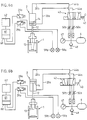
- On the switching valve 42 are flexible pressure hoses 44a, b connected, which at the beginning of the connecting line 3 merge into the pressure pipes 20a, b, which lead to the connections 21a, b the drive unit 2 (Fig. 2).
- Another flexible Pressure hose 45 merges into a pressure pipe (not shown), that leads to the pressure accumulator 6 in the connecting line 5. He connects to a junction piece 46, which connections with a manometer 47 belonging to the operating unit 38 as Pressure display element - other elements could also be used visual pressure display are used, e.g. B.
- the quick connector 49 which is shown in FIG Device for refilling the pressure reservoir 6 z. B. from one serves mobile pressure accumulator 52 (Fig. 4a, b) contains a Ball check valve with a ball 53 (Fig. 5), which with an upwardly projecting extension 54 is provided. she will from the overpressure in the pressure accumulator 6 in the position shown held.
- a connector 55 is now at the end of a mobile pressure accumulator 52 outgoing pressure pipe 56, which also a ball check valve with a ball 57 contains, on the quick connector 49, since the Pressure in the mobile pressure accumulator 52 is higher than in the pressure accumulator 6, the ball 53 pressed down until it hits one Stop grid 58 is present, so that with further downward movement of the connecting piece 55, the ball 57 through the extension 54 raised and the connection between the mobile pressure accumulator 52 and the pressure accumulator 6 opened and the latter refilled becomes. Is the pressure in the mobile pressure accumulator 52 lower than in Pressure accumulator 6, only the ball 57 is raised while the Check valve in quick connector 49 remains closed.
- Quick connector 49 and the connector 55 form one Quick coupling between the mobile pressure accumulator 52 and the stationary pressure accumulator 6 by the force that the plugged connector 55 due to the weight of the exerts mobile pressure accumulator 52 on the quick connector 49, is opened while at the same time it is tight to the outside.
- the connector 55 close the on both sides Check valves.
- the electrical outgoing from the magnetic switches 29a, b Lines 30 lead z. T. to display elements 59a, b the control unit 38, which indicate whether the piston 14 takes up the upper or lower end position.
- the power supply of the Magnetic switch 29a, b goes (FIG. 6a, b) from an accumulator 60 from which is fed by a control unit 61 from solar cells 62 becomes.
- the accumulator 60, the control unit 61 and the Solar cells 62 are integrated in the actuation unit 4.
- the closing movement follows the opening described above completely analog.
- the speed of both movements can controlled by the adjustable throttle valves 50a, b that no dangerous pressure surges can occur.
- the described device can be modified in many ways will. So instead of purely pneumatic energy supply and Drive unit a hydraulic or mixed solution be provided. In the preferred purely pneumatic The device, as described above, can Pressure accumulator 6 in the lower part 34 of the actuation unit 4 be housed. It can also be missing; to operate the The device will then always be a mobile pressure accumulator or a other pressure source used.
- the version with pressure accumulator 6 has great advantages. Not only does it allow multiple switching operations as described to perform them in a very convenient manner without external pressure also offers the possibility of further operating simplifications to provide.
- the control unit 61 can thus be designed such that they have switching commands over a telephone line or radio can be transferred, collected and implemented. It can too comprise a transmitter which, for. B. in certain system states Sends signals received by a control center and can be processed. With such a device can much faster than before z. B. reacts to a broken pipe will. Codes can be used for remote and direct operation are used or queried, whereby manipulations by Unauthorized persons are almost impossible.
- the power supply for the electrical components can take place through the solar cells 62 in connection with the accumulator 60 also exclusively by means of an accumulator or via a electrical conduction.
- the closing time is fixed by blinds can be set.
- FIGS. 7a, b remove.
- Upstream of the armature 1 branches from the line a supply connection 63, which is connected via a filter 64 a connection of the switching valve 42 is connected.
- the administration serves as a pressure source and supplies those for switching operations required energy.
- the switching valve is switched to open the valve, see above that it connects the feed connection 63 with the one below the piston 14 lying area connects and the above the piston 14th lying area with the outlet (Fig. 7b) so that the piston 14 raised and the valve is opened.
- the valve 1 and the drive unit 2 can - depending on Type of line - pneumatic or hydraulic and in be constructed essentially as shown in Fig. 2.
- the Switch valve 42 which is electrically switchable, is in the bottom arranged, preferably attached to the drive unit 2.
- the Actuating unit is simplified because it is not pneumatic Elements, but only - in addition to the accumulator 60, the Control unit 61 and the solar cells 62 - display elements and an electrical switch (not shown) for the Actuation of the switching valve 42 needs to have.
- the actuating unit 4 contains only electrical ones Cables.
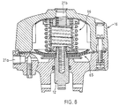
- the drive unit 2 can, if only a small stroke is required instead of as a piston drive according to FIG. 2 as Membrane drive (Fig. 8) may be formed.
- the inside of the Housing 16 is flexible instead of by a piston Membrane 65 divided into an upper and a lower area. In The lower area opens the connection 21a, in the upper area Connection 21b.
- the membrane 65 carries the spindle 12 with the Final body (not shown).
- the diaphragm drive can remaining in the same with the other components of the facility Be connected like the piston drive.
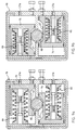
- sc can be used as Drive unit can be used as part of a rotary actuator 9a, 9b is shown in its two end positions.
- a rotary actuator 9a, 9b In its housing 16 with connections 21a, b are two pistons 14 mounted in opposite directions. Your movement is through Racks 67 and a gear 68 on a pivot shaft (not shown) transferred on which the gear 68 is attached and which carries the pivoting end body.
- the Basic position of the rotary actuator, that of the closed position (Fig. 9a), is determined by spring assemblies 66.
Landscapes
- Engineering & Computer Science (AREA)
- General Engineering & Computer Science (AREA)
- Mechanical Engineering (AREA)
- Fluid-Driven Valves (AREA)
- Mechanically-Actuated Valves (AREA)
Description
- Fig. 1
- eine schematisierte Uebersichtsdarstellung einer erfindungsgemässen Einrichtung einschliesslich einer Armatur gemäss einer ersten Ausführungsform der Erfindung,
- Fig. 2
- einen Schnitt durch eine Armatur mit Antriebseinheit der Einrichtung nach Fig. 1, links in der Stellung "offen", rechts in der Stellung "geschlossen",
- Fig. 3
- einen Schnitt durch eine Betätigungseinheit der Einrichtung nach Fig. 1,
- Fig. 4a
- eine Seitenansicht der Betätigungseinheit von Fig. 3, mit mobilem Druckspeicher,
- Fig. 4b
- eine Draufsicht auf die Betätigungseinheit von Fig. 3, mit mobilem Druckspeicher,
- Fig. 5
- einen Schnitt durch eine Schnellkupplung zwischen der Betätigungseinheit und dem mobilen Druckspeicher,
- Fig. 6a
- ein Schaltschema der Einrichtung nach Fig. 1 im Schaltzustand "geschlossen",
- Fig. 6b
- ein Schaltschema der Einrichtung nach Fig. 1 im Schaltzustand "offen",
- Fig. 7a
- ein Schaltschema einer Einrichtung gemäss einer zweiten Ausführungsform der Erfindung im Schaltzustand "geschlossen",
- Fig. 7b
- ein Schaltschema entsprechend Fig. 7a, Schaltzustand "offen",
- Fig. 8
- einen Schnitt durch eine Antriebseinheit gemäss einer zweiten Ausführungsform in Schliessstellung,
- Fig. 9a
- einen Schnitt durch eine Antriebseinheit gemäss einer dritten Ausführungsform, in Schliessstellung und
- Fig. 9b
- einen Schnitt durch die Antriebseinheit nach Fig. 9a, in Offenstellung.
Claims (23)
- Einrichtung zum Schliessen und Oeffnen einer erdverlegten Armatur (1) mittels einer an dieselbe angebauten Antriebseinheit (2), dadurch gekennzeichnet, dass sie eine von der Antriebseinheit (2) räumlich getrennte Betätigungseinheit (4) umfasst, welche mindestens zum Teil an oder über dem Boden angeordnet und durch mindestens einen der Uebertragung von Energie oder Steuersignalen für die Betätigung der Armatur (1) dienenden Verbindungsleitungsstrang (3) mit der Antriebseinheit (2) verbunden ist, welche einen pneumatischen oder hydraulischen Antrieb mit einem durch einseitige Druckbeaufschlagung auslenkbaren Element sowie mit mindestens einem ersten Anschluss (21a) enthält, der zur Betätigung der Armatur (1) über ein von der Betätigungseinheit (4) aus betätigbares Schaltventil (42) mit Druck aus einer Druckquelle beaufschlagbar ist.
- Einrichtung nach Anspruch 1, dadurch gekennzeichnet, dass als Druckquelle ein Anschluss für Druckzufuhr von aussen an der Betätigungseinheit (4) angeordnet ist.
- Einrichtung nach Anspruch 2, dadurch gekennzeichnet, dass der Anschluss als Schnellanschluss (49) mit einem Rückschlagventil ausgebildet ist.
- Einrichtung nach einem der Ansprüche 1 bis 3, dadurch gekennzeichnet, dass als Druckquelle ein Druckspeicher (6) vorhanden ist.
- Einrichtung nach Anspruch 4, dadurch gekennzeichnet, dass der Druckspeicher (6) mit einem Anschluss an der Betätigungseinheit (4) verbunden ist.
- Einrichtung nach den Ansprüchen 3 und 5, dadurch gekennzeichnet, dass der Druckspeicher (6) mit dem Schnellanschluss (49) verbunden ist.
- Einrichtung nach einem der Ansprüche 3 bis 6, dadurch gekennzeichnet, dass sie mindestens einen mobilen Druckspeicher (52) mit einem Anschlussstück (55) umfasst, welches mit dem Schnellanschluss (49) eine Schnellkupplung bildet, die durch Anpressen des Anschlusstücks (55) an den Schnellanschluss (49) geöffnet werden kann und zugleich nach aussen dicht ist.
- Einrichtung nach Anspruch 7, dadurch gekennzeichnet, dass das Eigengewicht des mobilen Druckspeichers (52) einen zum Oeffnen der Schnellkupplung ausreichenden Anpressdruck zwischen dem Anschlussstück (55) und dem Schnellanschluss (49) erzeugt.
- Einrichtung nach Anspruch 1, dadurch gekennzeichnet, dass als Druckquelle ein stromaufwärts der Armatur (1) angeordneter Speiseanschluss (63) an der erdverlegten Armatur dient.
- Einrichtung nach einem der Ansprüche 1 bis 9, dadurch gekennzeichnet, dass das Schaltventil (42) mindestens als 3/2-Wegeventil ausgebildet ist, welches mindestens den ersten Anschluss (21a) der Antriebseinheit (2) mit einem Auslass verbinden kann.
- Einrichtung nach Anspruch 10, dadurch gekennzeichnet, dass eine Druckbeaufschlagung des ersten Anschlusses (21a) der Antriebseinheit (2) ein Oeffnen der erdverlegten Armatur bewirkt und die Antriebseinheit (2) mindestens einen zweiten Anschluss (21b) aufweist, dessen Druckbeaufschlagung ein Schliessen der Armatur bewirkt und das Schaltventil (42) mindestens als 4/2-Wegeventil ausgebildet ist, welches den ersten Anschluss (21a) mit der Druckquelle und zugleich den zweiten Anschluss (21b) mit einem Auslass oder den zweiten Anschluss (21b) mit der Druckquelle und zugleich den ersten Anschluss (21a) mit einem Auslass verbinden kann.
- Einrichtung nach einem der Ansprüche 1 bis 11, dadurch gekennzeichnet, dass die Antriebseinheit (2) mindestens eine Verriegelung zur Arretierung des auslenkbaren Elements in einer Endstellung aufweist.
- Einrichtung nach Anspruch 12, dadurch gekennzeichnet, dass die mindestens eine Verriegelung als Schnappverriegelung ausgebildet ist.
- Einrichtung nach einem der Ansprüche 1 bis 12, dadurch gekennzeichnet, dass die Antriebseinheit (2) eine Federanordnung (66) enthält zur Beaufschlagung des auslenkbaren Elements mit einer gegen eine Grundstellung gerichteten Kraft.
- Einrichtung nach einem der Ansprüche 1 bis 14, dadurch gekennzeichnet, dass die Antriebseinheit (2) mindestens einen Endschalter umfasst, welcher zur Anzeige, ob sich das auslenkbare Element in einer Endstellung befindet, mit einem Anzeigeelement (56a, 59b) an der Betätigungseinheit (4) verbunden ist.
- Einrichtung nach einem der Ansprüche 1 bis 15, dadurch gekennzeichnet, dass allfällig in der Betätigungseinheit (4) eingebaute Ventile an oder unter dem Boden angeordnet sind.
- Einrichtung nach einem der Ansprüche 1 bis 16, dadurch gekennzeichnet, dass die Betätigungseinheit (4) eine oberhalb des Bodens angeordnete Bedieneinheit (38) aufweist, an welcher sämtliche allfälligen Anschlüsse, Betätigungselemente zur Betätigung von Ventilen und Anzeigeelemente angeordnet sind.
- Einrichtung nach Anspruch 17, dadurch gekennzeichnet, dass die Betätigungseinheit (4) einen über dem Boden liegenden Oberteil (37), welcher die Bedieneinheit (38) enthält und einen im Boden verankerten, höchstens geringfügig über denselben ragenden Unterteil (34) umfasst, mit welchem der Oberteil (37) über eine Sollbruchzone verbunden ist und dass allfällig im Oberteil (37) angeordnete Ventile mittels flexibler Druckschläuche (44a, 44b, 45) an erdverlegte Druckrohre (20a, 20b) angeschlossen sind.
- Einrichtung nach einem der Ansprüche 1 bis 18, dadurch gekennzeichnet, dass die Betätigungseinheit (4) eine elektrische Steuereinheit (61) umfasst.
- Einrichtung nach Anspruch 19, dadurch gekennzeichnet, dass die Betätigungseinheit (4) zur Stromversorgung mit einem Akkumulator (60) ausgerüstet ist.
- Einrichtung nach Anspruch 20, dadurch gekennzeichnet, dass die Betätigungseinheit (4) mit Solarzellen (62) zur Aufladung des Akkumulators (60) ausgerüstet ist.
- Einrichtung nach einem der Ansprüche 1 bis 21, dadurch gekennzeichnet, dass die Antriebseinheit (2) oberhalb der erdverlegten Armatur angeordnet und oben wie seitlich von einer nässe- und wärmeisolierenden Schutzhaube (31) umgeben ist.
- Einrichtung umfassend eine Armatur (1) sowie eine Einrichtung nach einem der Ansprüche 1 bis 22 zum Schliessen und Oeffnen derselben.
Applications Claiming Priority (2)
| Application Number | Priority Date | Filing Date | Title |
|---|---|---|---|
| CH2495/93 | 1993-08-20 | ||
| CH249593 | 1993-08-20 |
Publications (2)
| Publication Number | Publication Date |
|---|---|
| EP0639737A1 EP0639737A1 (de) | 1995-02-22 |
| EP0639737B1 true EP0639737B1 (de) | 1998-01-07 |
Family
ID=4235098
Family Applications (1)
| Application Number | Title | Priority Date | Filing Date |
|---|---|---|---|
| EP19940112341 Expired - Lifetime EP0639737B1 (de) | 1993-08-20 | 1994-08-08 | Pneumatischer oder hydraulischer Antrieb einer erdverlegten Armatur |
Country Status (2)
| Country | Link |
|---|---|
| EP (1) | EP0639737B1 (de) |
| DE (1) | DE59404932D1 (de) |
Families Citing this family (5)
| Publication number | Priority date | Publication date | Assignee | Title |
|---|---|---|---|---|
| JP3400557B2 (ja) * | 1994-08-10 | 2003-04-28 | 大阪瓦斯株式会社 | 弁駆動装置 |
| US5918618A (en) * | 1996-07-02 | 1999-07-06 | National Fuel Gas Distribution Corp. | Natural gas shut off system |
| EP2708967B1 (de) | 2012-09-13 | 2016-04-27 | Fabian Sacharowitz | Dezentrale elektrische stellvorrichtung |
| FR3035469B1 (fr) * | 2015-04-23 | 2017-05-12 | Snecma | Vanne et procede de commande |
| KR101926708B1 (ko) * | 2018-01-17 | 2018-12-07 | 한국전력기술 주식회사 | 투명 케이싱과 이중화 링 다이어프램을 사용하는 제어밸브 공압 구동기 |
Family Cites Families (6)
| Publication number | Priority date | Publication date | Assignee | Title |
|---|---|---|---|---|
| DE349305C (de) * | 1919-08-24 | 1922-02-28 | Ernst Mields | Absperrventil mit Fernsteuerung durch einen Dampfkolben |
| US2834569A (en) * | 1955-11-16 | 1958-05-13 | Chapman Valve And Mfg Company | Piston actuated valve with restraining detent |
| US3788341A (en) * | 1972-05-04 | 1974-01-29 | Southwestern Mfg Co | Pressure responsive valve system |
| US4141533A (en) * | 1976-12-09 | 1979-02-27 | United Technologies Corporation | Hydraulically operated shutoff valve |
| JPS5943280A (ja) * | 1982-09-06 | 1984-03-10 | Kobe Steel Ltd | バルブ用アクチユエ−タ |
| DE4014474C1 (en) * | 1990-05-07 | 1992-01-23 | Apv Rosista Gmbh, 4750 Unna, De | Disc valve control head - is mounted on valve housing via spacer with inspection holes |
-
1994
- 1994-08-08 EP EP19940112341 patent/EP0639737B1/de not_active Expired - Lifetime
- 1994-08-08 DE DE59404932T patent/DE59404932D1/de not_active Expired - Lifetime
Also Published As
| Publication number | Publication date |
|---|---|
| EP0639737A1 (de) | 1995-02-22 |
| DE59404932D1 (de) | 1998-02-12 |
Similar Documents
| Publication | Publication Date | Title |
|---|---|---|
| DE69307300T2 (de) | Versenkbare elektrische Sperre | |
| DE69614699T2 (de) | Vereinfachter christbaum mit unterwasser-testbaum | |
| EP2852507B2 (de) | Vorrichtung zur induktiven übertragung elektrischer energie | |
| DE19743477A1 (de) | Duschanordnung mit Strahlarteinstellung | |
| EP0639737A1 (de) | Pneumatischer oder hydraulischer Antrieb einer erdverlegten Armatur | |
| DE2158977A1 (de) | Ausfahrbare sperre fuer verkehrswege | |
| EP3957802B1 (de) | Ventil für bodenablauf | |
| DE10207698B4 (de) | Strebsteuerung für den Strebausbau | |
| EP2156017B1 (de) | Schiidsteuereinrichtung zur durchführung der ausbaufunktion einer ausbaueinheit beim strebausbau in einem bergwerk | |
| DE4031245C2 (de) | ||
| DE1905565A1 (de) | Einhebelsteuervorrichtung | |
| DE102022112185A1 (de) | Wasserauslaufarmatur mit Spüleinrichtung | |
| EP1515409B1 (de) | Unterirdische Schaltanlage | |
| DE2649650A1 (de) | Selbsttaetig arbeitende beregnungseinrichtung | |
| EP2508696A2 (de) | Schließsystem für Türen und Klappen aller Art | |
| DE926324C (de) | Hoehenverstellbare und ortsveraenderliche Arbeitsbuehne auf einem in vertikaler Richtung teleskopartig aus- und einziehbaren Rohrmast | |
| DE102009009312B4 (de) | Steuerungsvorrichtung für eine mobile Arbeitsmaschine | |
| DE3102865A1 (de) | "sicherheits-absperrvorrichtung fuer haus-gasanschluesse" | |
| DE60308111T2 (de) | Multifunktionales versenkbares Versorgungssystem | |
| DE19928036A1 (de) | Aufahrbarer Poller für Absperrungen | |
| DE2646844A1 (de) | Verriegelung fuer schleusentueren | |
| DE102006053097A1 (de) | Hebesystem für Müllbehälter sowie Entsorgungsfahrzeug | |
| DE102006022162B3 (de) | Unterflurhydrant | |
| CH423919A (de) | Unterirdische Kabine für elektrische Verteilanlagen | |
| WO2013107482A1 (de) | Gaszapfanlage |
Legal Events
| Date | Code | Title | Description |
|---|---|---|---|
| PUAI | Public reference made under article 153(3) epc to a published international application that has entered the european phase |
Free format text: ORIGINAL CODE: 0009012 |
|
| AK | Designated contracting states |
Kind code of ref document: A1 Designated state(s): CH DE FR GB IT LI |
|
| 17P | Request for examination filed |
Effective date: 19950718 |
|
| GRAG | Despatch of communication of intention to grant |
Free format text: ORIGINAL CODE: EPIDOS AGRA |
|
| 17Q | First examination report despatched |
Effective date: 19970417 |
|
| GRAG | Despatch of communication of intention to grant |
Free format text: ORIGINAL CODE: EPIDOS AGRA |
|
| GRAH | Despatch of communication of intention to grant a patent |
Free format text: ORIGINAL CODE: EPIDOS IGRA |
|
| RAP1 | Party data changed (applicant data changed or rights of an application transferred) |
Owner name: VON ROLL HOLDING AG |
|
| GRAH | Despatch of communication of intention to grant a patent |
Free format text: ORIGINAL CODE: EPIDOS IGRA |
|
| GRAA | (expected) grant |
Free format text: ORIGINAL CODE: 0009210 |
|
| AK | Designated contracting states |
Kind code of ref document: B1 Designated state(s): CH DE FR GB IT LI |
|
| REG | Reference to a national code |
Ref country code: CH Ref legal event code: NV Representative=s name: A. BRAUN, BRAUN, HERITIER, ESCHMANN AG PATENTANWAE Ref country code: CH Ref legal event code: EP |
|
| GBT | Gb: translation of ep patent filed (gb section 77(6)(a)/1977) |
Effective date: 19980112 |
|
| ITF | It: translation for a ep patent filed | ||
| REF | Corresponds to: |
Ref document number: 59404932 Country of ref document: DE Date of ref document: 19980212 |
|
| ET | Fr: translation filed | ||
| PLBE | No opposition filed within time limit |
Free format text: ORIGINAL CODE: 0009261 |
|
| STAA | Information on the status of an ep patent application or granted ep patent |
Free format text: STATUS: NO OPPOSITION FILED WITHIN TIME LIMIT |
|
| 26N | No opposition filed | ||
| REG | Reference to a national code |
Ref country code: GB Ref legal event code: IF02 |
|
| REG | Reference to a national code |
Ref country code: CH Ref legal event code: PUE Owner name: VON ROLL INFRANET SA Free format text: VON ROLL HOLDING AG##4563 GERLAFINGEN (CH) -TRANSFER TO- VON ROLL INFRANET SA##2830 CHOINDEZ (CH) |
|
| PGFP | Annual fee paid to national office [announced via postgrant information from national office to epo] |
Ref country code: FR Payment date: 20030725 Year of fee payment: 10 |
|
| PGFP | Annual fee paid to national office [announced via postgrant information from national office to epo] |
Ref country code: GB Payment date: 20030806 Year of fee payment: 10 |
|
| REG | Reference to a national code |
Ref country code: GB Ref legal event code: 732E |
|
| REG | Reference to a national code |
Ref country code: FR Ref legal event code: TP |
|
| PG25 | Lapsed in a contracting state [announced via postgrant information from national office to epo] |
Ref country code: GB Free format text: LAPSE BECAUSE OF NON-PAYMENT OF DUE FEES Effective date: 20040808 |
|
| GBPC | Gb: european patent ceased through non-payment of renewal fee |
Effective date: 20040808 |
|
| PG25 | Lapsed in a contracting state [announced via postgrant information from national office to epo] |
Ref country code: FR Free format text: LAPSE BECAUSE OF NON-PAYMENT OF DUE FEES Effective date: 20050429 |
|
| REG | Reference to a national code |
Ref country code: FR Ref legal event code: ST |
|
| PG25 | Lapsed in a contracting state [announced via postgrant information from national office to epo] |
Ref country code: IT Free format text: LAPSE BECAUSE OF NON-PAYMENT OF DUE FEES;WARNING: LAPSES OF ITALIAN PATENTS WITH EFFECTIVE DATE BEFORE 2007 MAY HAVE OCCURRED AT ANY TIME BEFORE 2007. THE CORRECT EFFECTIVE DATE MAY BE DIFFERENT FROM THE ONE RECORDED. Effective date: 20050808 |
|
| REG | Reference to a national code |
Ref country code: CH Ref legal event code: PUE Owner name: VONROLL INFRATEC (INVESTMENT) AG Free format text: VONROLL HYDROTEC SA# #2830 CHOINDEZ (CH) -TRANSFER TO- VONROLL INFRATEC (INVESTMENT) AG#BAHNHOFSTRASSE 23#6300 ZUG (CH) Ref country code: CH Ref legal event code: PFA Owner name: VONROLL HYDROTEC SA Free format text: VON ROLL INFRANET SA# #2830 CHOINDEZ (CH) -TRANSFER TO- VONROLL HYDROTEC SA# #2830 CHOINDEZ (CH) |
|
| REG | Reference to a national code |
Ref country code: CH Ref legal event code: PFA Owner name: VONROLL INFRATEC (INVESTMENT) AG Free format text: VONROLL INFRATEC (INVESTMENT) AG#BAHNHOFSTRASSE 23#6300 ZUG (CH) -TRANSFER TO- VONROLL INFRATEC (INVESTMENT) AG#BAHNHOFSTRASSE 23#6300 ZUG (CH) |
|
| PGFP | Annual fee paid to national office [announced via postgrant information from national office to epo] |
Ref country code: CH Payment date: 20110823 Year of fee payment: 18 |
|
| PGFP | Annual fee paid to national office [announced via postgrant information from national office to epo] |
Ref country code: DE Payment date: 20110830 Year of fee payment: 18 |
|
| REG | Reference to a national code |
Ref country code: CH Ref legal event code: PL |
|
| PG25 | Lapsed in a contracting state [announced via postgrant information from national office to epo] |
Ref country code: CH Free format text: LAPSE BECAUSE OF NON-PAYMENT OF DUE FEES Effective date: 20120831 Ref country code: LI Free format text: LAPSE BECAUSE OF NON-PAYMENT OF DUE FEES Effective date: 20120831 |
|
| PG25 | Lapsed in a contracting state [announced via postgrant information from national office to epo] |
Ref country code: DE Free format text: LAPSE BECAUSE OF NON-PAYMENT OF DUE FEES Effective date: 20130301 |
|
| REG | Reference to a national code |
Ref country code: DE Ref legal event code: R119 Ref document number: 59404932 Country of ref document: DE Effective date: 20130301 |