EP0638852A2 - Bilderzeugungsgerät mit einer Aufladevorrichtung vor der Übertragungsstation - Google Patents
Bilderzeugungsgerät mit einer Aufladevorrichtung vor der Übertragungsstation Download PDFInfo
- Publication number
- EP0638852A2 EP0638852A2 EP94112358A EP94112358A EP0638852A2 EP 0638852 A2 EP0638852 A2 EP 0638852A2 EP 94112358 A EP94112358 A EP 94112358A EP 94112358 A EP94112358 A EP 94112358A EP 0638852 A2 EP0638852 A2 EP 0638852A2
- Authority
- EP
- European Patent Office
- Prior art keywords
- image forming
- forming apparatus
- charger
- photosensitive drum
- transfer
- Prior art date
- Legal status (The legal status is an assumption and is not a legal conclusion. Google has not performed a legal analysis and makes no representation as to the accuracy of the status listed.)
- Withdrawn
Links
- CBENFWSGALASAD-UHFFFAOYSA-N Ozone Chemical compound [O-][O+]=O CBENFWSGALASAD-UHFFFAOYSA-N 0.000 claims description 22
- 238000004140 cleaning Methods 0.000 claims description 22
- 230000003014 reinforcing effect Effects 0.000 claims description 6
- 238000009877 rendering Methods 0.000 claims description 2
- 238000010276 construction Methods 0.000 description 13
- 238000010586 diagram Methods 0.000 description 5
- 239000002245 particle Substances 0.000 description 5
- 229920003002 synthetic resin Polymers 0.000 description 5
- 239000000057 synthetic resin Substances 0.000 description 5
- 238000005452 bending Methods 0.000 description 4
- 239000011521 glass Substances 0.000 description 4
- 230000002093 peripheral effect Effects 0.000 description 4
- 230000003287 optical effect Effects 0.000 description 3
- 238000003466 welding Methods 0.000 description 3
- OKTJSMMVPCPJKN-UHFFFAOYSA-N Carbon Chemical compound [C] OKTJSMMVPCPJKN-UHFFFAOYSA-N 0.000 description 2
- XEEYBQQBJWHFJM-UHFFFAOYSA-N Iron Chemical compound [Fe] XEEYBQQBJWHFJM-UHFFFAOYSA-N 0.000 description 2
- 238000007599 discharging Methods 0.000 description 2
- 238000003384 imaging method Methods 0.000 description 2
- 238000004519 manufacturing process Methods 0.000 description 2
- 238000007789 sealing Methods 0.000 description 2
- 238000010521 absorption reaction Methods 0.000 description 1
- 230000002411 adverse Effects 0.000 description 1
- XAGFODPZIPBFFR-UHFFFAOYSA-N aluminium Chemical compound [Al] XAGFODPZIPBFFR-UHFFFAOYSA-N 0.000 description 1
- 229910052782 aluminium Inorganic materials 0.000 description 1
- 239000004020 conductor Substances 0.000 description 1
- 230000000694 effects Effects 0.000 description 1
- 229910052742 iron Inorganic materials 0.000 description 1
- 229920000728 polyester Polymers 0.000 description 1
- 229910001220 stainless steel Inorganic materials 0.000 description 1
- 239000010935 stainless steel Substances 0.000 description 1
- WFKWXMTUELFFGS-UHFFFAOYSA-N tungsten Chemical compound [W] WFKWXMTUELFFGS-UHFFFAOYSA-N 0.000 description 1
- 229910052721 tungsten Inorganic materials 0.000 description 1
- 239000010937 tungsten Substances 0.000 description 1
Images


Classifications
-
- G—PHYSICS
- G03—PHOTOGRAPHY; CINEMATOGRAPHY; ANALOGOUS TECHNIQUES USING WAVES OTHER THAN OPTICAL WAVES; ELECTROGRAPHY; HOLOGRAPHY
- G03G—ELECTROGRAPHY; ELECTROPHOTOGRAPHY; MAGNETOGRAPHY
- G03G15/00—Apparatus for electrographic processes using a charge pattern
- G03G15/14—Apparatus for electrographic processes using a charge pattern for transferring a pattern to a second base
- G03G15/16—Apparatus for electrographic processes using a charge pattern for transferring a pattern to a second base of a toner pattern, e.g. a powder pattern, e.g. magnetic transfer
- G03G15/169—Apparatus for electrographic processes using a charge pattern for transferring a pattern to a second base of a toner pattern, e.g. a powder pattern, e.g. magnetic transfer with means for preconditioning the toner image before the transfer
-
- G—PHYSICS
- G03—PHOTOGRAPHY; CINEMATOGRAPHY; ANALOGOUS TECHNIQUES USING WAVES OTHER THAN OPTICAL WAVES; ELECTROGRAPHY; HOLOGRAPHY
- G03G—ELECTROGRAPHY; ELECTROPHOTOGRAPHY; MAGNETOGRAPHY
- G03G15/00—Apparatus for electrographic processes using a charge pattern
- G03G15/14—Apparatus for electrographic processes using a charge pattern for transferring a pattern to a second base
- G03G15/16—Apparatus for electrographic processes using a charge pattern for transferring a pattern to a second base of a toner pattern, e.g. a powder pattern, e.g. magnetic transfer
- G03G15/163—Apparatus for electrographic processes using a charge pattern for transferring a pattern to a second base of a toner pattern, e.g. a powder pattern, e.g. magnetic transfer using the force produced by an electrostatic transfer field formed between the second base and the electrographic recording member, e.g. transfer through an air gap
- G03G15/1635—Apparatus for electrographic processes using a charge pattern for transferring a pattern to a second base of a toner pattern, e.g. a powder pattern, e.g. magnetic transfer using the force produced by an electrostatic transfer field formed between the second base and the electrographic recording member, e.g. transfer through an air gap the field being produced by laying down an electrostatic charge behind the base or the recording member, e.g. by a corona device
- G03G15/165—Arrangements for supporting or transporting the second base in the transfer area, e.g. guides
-
- G—PHYSICS
- G03—PHOTOGRAPHY; CINEMATOGRAPHY; ANALOGOUS TECHNIQUES USING WAVES OTHER THAN OPTICAL WAVES; ELECTROGRAPHY; HOLOGRAPHY
- G03G—ELECTROGRAPHY; ELECTROPHOTOGRAPHY; MAGNETOGRAPHY
- G03G2215/00—Apparatus for electrophotographic processes
- G03G2215/00362—Apparatus for electrophotographic processes relating to the copy medium handling
- G03G2215/00367—The feeding path segment where particular handling of the copy medium occurs, segments being adjacent and non-overlapping. Each segment is identified by the most downstream point in the segment, so that for instance the segment labelled "Fixing device" is referring to the path between the "Transfer device" and the "Fixing device"
- G03G2215/00409—Transfer device
Definitions
- the present invention relates to an image forming apparatus provided with a pre-transfer charger to improve the efficiency in transferring a toner image onto a copy sheet.
- an image forming apparatus comprises a toner image forming unit for forming a toner image, and a toner image transferring device for transferring the toner image onto a copy sheet dispensed from a cassette.
- the toner image forming unit has a photosensitive drum. Specifically, the copy sheet is transported near a surface of the photosensitive drum and the toner image is transferred onto the copy sheet from the photosensitive drum. The copy sheet is then discharged from the apparatus after the toner image is fixed on the copy sheet by a fixing unit.
- a charger before a toner image transferring device to improve the transferring efficiency of toner image from the surface of the photosensitive drum onto the copy sheet.
- a charger has been generally called a pre-transfer charger.
- Fig. 14 is a schematic diagram showing an arrangement of a photosensitive drum and its peripheral devices in a conventional image forming apparatus.
- a surface of a photosensitive drum 10 is positively charged at a specified level by a main charger 11, and exposed to a light image A reflected from an original document to form an electrostatic latent image. Thereafter, an unnecessary area of the charged surface of the photosensitive drum 10 is removed by a blank lamp 12.
- a developing device 13 containing negatively charged toner particles. Negatively charged toner particles are electrically attracted to the positive latent image on the photosensitive drum surface to develop a toner image.
- a copy sheet is transported to the photosensitive drum 10 by a pair of registration rollers 24.
- the copy sheet is guided through a sheet transport passage 25 up to the surface of the photosensitive drum 10.
- the sheet transport passage 25 is constructed by an upper guide plate and a lower guide plate.
- the copy sheet is applied with positive electric charges by a transferring device 14 to transfer the toner image onto the copy sheet from the photosensitive drum 10.
- the copy sheet bearing the toner image is separated from the surface of the photosensitive drum 10 by a separating device 15 which is driven by an alternating current.
- a pre-transfer charger 101 is arranged before the sheet transport passage 25 with respect to the rotating direction of the photosensitive drum 10.
- the pre-transfer charger 101 is driven by an alternating current whose negative component is slightly greater than the positive component.
- the pre-transfer charger 101 is provided to remove positive electric charges just below the toner image on the surface of the photosensitive drum 10, and to increase the electrical level of the negatively charged toner image.
- the pre-transfer charger 101 improves the transferring efficiency of toner image onto a copy sheet. Also, the pre-transfer charger 101 assists the transferring device 14 in transferring the toner image onto a copy sheet which cannot be sufficiently charged by the transferring device due to absorption of moisture in the air.
- a pre-transfer charger is, as mentioned above, provided in a limited small space where a developing device, transferring device, sheet transport passage, registration roller pair are densely arranged. Accordingly, there has been another strong demand for a new construction which makes it possible to efficiently remove ozone from a pre-transfer charger without increasing the apparatus size.
- a pre-transfer charger is required to be held in a precise positional relationship with respect to a photosensitive drum and sheet transport passage in addition to being provided in a densely arranged space as mentioned above. Accordingly, the construction has been demanded which enables the operator to mount a pre-transfer charger in a specified position easily and accurately when replacing a broken pre-transfer charger with a new charger.
- the present invention is directed to an image forming apparatus comprising: a photosensitive drum rotatable in a specified direction on which an electrostatic latent image is formed; a developer disposed near the photosensitive drum for developing the electrostatic latent image into a toner image; a transfer disposed on a downstream of the developer with respect to the rotation of the photosensitive drum for transferring the toner image onto copy paper; a charger disposed between the developer and the transfer for charging the photosensitive drum at a specified level to assure a smooth transfer of the toner image from the photosensitive drum to the copy paper, the charger including a casing formed with a guide portion for guiding the copy paper to the transfer.
- a guide plate may be disposed between the charger casing and the transfer to define a copy paper transport passage in combination with the guide portion of the charger casing.
- the guide portion may be provided with a film having a low friction coefficient.
- the casing may be made of a plurality of separatable members. Further, the casing may be provided with an intermediate vertical reinforcing member defining a first chamber and a second chamber, the first chamber having an opening facing the photosensitive drum.
- an enclosure member may be provided on an underside of the developer to define an ozone removal space communicating with the first and second chambers through the guide opening formed in the first chamber and an outflow opening formed in the second chamber.
- a support frame including a front support wall having holding means for holding a front portion of the charger, and a rear support wall having an engagement hole and a guide hole; and a charger including a rear portion having an engagement projection engageable with the engagement hole and a slide member slidable in the guide hole; thereby mounting the charger on the support frame by inserting the slide member in the guide hole, moving the charger further rearward while the slide member being supported at the guide hole until the engagement projection engages with the engagement hole, and rendering the front portion of the charger held by the holding means.
- the copy paper guide portion is formed on the casing of the charger. This makes it possible to discard the upper guide plate which has been used in the conventional image forming apparatus, thus reducing the number of parts and the production costs. Also, the charger can be provided without increasing the size of image forming apparatus.
- the combination of the guide plate and the guide portion enhances the reliability of copy paper transport.
- the provision of the film assures smooth transport of copy paper.
- the charger casing which is constructed by a plurality of separatable members suppresses high-frequency vibration of the charger casing.
- the provision of the intermediate vertical reinforcing member increases the bending and torsional strength of the charger casing.
- the provision of the ozone removal enclosure member on an underside of the developer enables efficient removing of ozone in a limited small space.
- the image forming assembly which integrally carries the photosensitive drum, developer, and charger is withdrawable from a main body of the image forming apparatus. Also, the charger is mounted on the support frame while the slide member on the rear portion of the charger is being supported on the guide hole formed in the rear wall of the support frame. Accordingly, charger replacement can be easily performed.
- Fig. 1 is a schematic diagram showing an overall construction of the image forming apparatus.
- the image forming apparatus comprises a contact glass 1 at a top thereof, a document presser 2 above the contact glass 1, an optical assembly L, an imaging assembly P and a sheet transport assembly for transporting a copy sheet.
- the optical assembly L includes an exposure lamp 3, a reflector 4, a light source for illuminating a document placed on the contact glass 1 while reciprocally moving in sidewise directions of the image forming apparatus, reflecting mirrors 5, 6, 7 for reflecting a light image along a specified optical path, a lens unit 8 for adjusting the magnification of light image, and a fixed mirror 9 for directing the reflected light image to a photosensitive drum 10.
- the imaging assembly P includes the photosensitive drum 10, a main charger 11, a blank lamp 12, a developing device 13, a pre-transfer charger 17, a transferring device 14, a separating device 15, and a cleaner 16.
- a peripheral surface of the photosensitive drum 10 is positively charged by the main charger 11 and then exposed to a light image to form an electrostatic latent image.
- the blank lamp 12 is adapted for removing electric charges on an unnecessary area of the photosensitive drum surface.
- the developing device 13 stores negatively charged toner particles. Toner particles are electrically attracted to the latent image on the photosensitive drum surface to thereby develop the latent image into a toner image.
- the transferring device 14 has a charger which is driven by a direct current, and positively charges a copy sheet to transfer the toner image to the copy sheet.
- the separating device 15 has a charger which is driven by an alternating current, and electrically separates the copy sheet bearing the toner image from the surface of the photosensitive drum 10.
- the cleaner 16 removes residual toner from the surface of the photosensitive drum 10 after the toner image transfer is completed.
- the sheet transport assembly includes cassettes 18, 19 for containing stacks of copy sheets of different sizes, respectively, feed rollers 20, 21 for feeding copy sheets one by one from the cassettes 18, 19, transport roller pairs 22, 23, and a registration roller pair 24 of an upper roller 241 and a lower roller 242, and a sheet transport passage 25 for guiding a copy sheet.
- the sheet transport assembly further includes on a downstream side after the photosensitive drum 10 a transport belt 26 for transporting the copy sheet bearing the toner image further downstream, a fixing device 27 for fixing the toner image on the copy sheet, and a pair of discharge rollers 28 for discharging the copy sheet bearing the fixed copy image to a discharge tray 29.
- the sheet transport passage 25 is defined by a guide member 251 and a guide portion 45 formed on the pre-transfer charger 17 as described later.
- the developing device 13, the upper roller 241, the pre-transfer charger 17, the photosensitive drum 10 and the cleaner 16 are assembled into a single unit to form an image forming unit S.
- the lower roller 242, the guide member 251, the transferring device 14, and the separating charger 15 are together mounted on a main body R of the image forming apparatus.
- the image forming unit S is separatable from the main body R along a copy sheet passing course.
- the image forming unit S is withdrawn from the main body R as shown in Fig. 3.
- the pre-transfer charger 17 is disposed near the copy sheet passing course along which the copy sheet is transported to the photosensitive drum 10.
- the pre-transfer charger 17 includes a charging wire 71 and a shield casing 72.
- the pre-transfer charger 17 is detachably mounted on a support frame of the image forming unit S to clean the wire or replace the wire with a new one.
- the shield casing 72 is constructed by an upper member 41, side member 42, and lower member 43 which are respectively shaped into specified forms as shown in Fig. 5B. These members are made of electrically conductive material, such as aluminum, iron, stainless steel.
- the upper member 41 and the side member 42 are connected with each other by spot welding.
- the upper and side members 41, 42 are connected with the lower member 43 by a screw.
- an L-shaped member 30 is connected on a specified position of the lower member 43 by spot welding.
- Fig. 5A shows the thus constructed shield casing 72.
- the shield casing 72 is, as shown in Fig. 5A, assembled into a box-like form which provides sufficient bending and torsional strengths. Also, the shield casing 72 has an opening facing only toward the photosensitive drum 10 to direct corona discharge of the charging wire 71 toward the photosensitive drum 10.
- the members 41, 42, 43 constituting the shield casing 72 have different shapes and sizes from one another, and thus have different natural frequencies.
- the shield casing 72 is constructed by connecting the members 41, 42, 43 by the means of spot welding and screw, instead of an entirely molded member. Accordingly, this construction will allow these members 41, 42, 43 to interfere with one another even when these members high-frequently vibrate due to the driving of the charging wire 71 to consequently suppress the entire of shield casing 72 from vibrating in higher magnitudes.
- the upper member 41 has a vertical portion 31a.
- the member 30 has a vertical portion 31b.
- the vertical portions 31a and 31b vertically face each other to define a guide opening 31c along which a cleaning member 32 is moved. A movement of the cleaning member 32 will be described later. Also, these vertical portions 31a and 31b increase the bending and torsional strength of the shield casing 72 and reinforce the shield casing 72.
- the vertical portions 31a, 31b are provided at an intermediate portion of the shield casing 72 to further increase the bending and torsional strengths of the shield casing 72. Also, the upper member 41 is formed with an upper opening 31d.
- the lower member 43 is formed with the guide portion 45.
- the lower member 43 is positioned along the copy sheet passing course.
- the guide portion 45 extends near the photosensitive drum 10 when the shield casing 72 is mounted, and is bent in such a direction as to guide the copy sheet being transported by the registration roller pair 24 into a gap between the transferring device 14 and the photosensitive drum 10.
- the sheet transport passage 25 is defined by the guide member 251 and a bottom portion and the guide portion 45 of the lower member 43 of the shield casing 72.
- the sheet transport passage 25 can be formed without providing an additional guide member. Accordingly, the number of parts to constitute the sheet transport passage 25 can be reduced, thereby reducing the production costs.
- This construction eliminates the need of providing a space for an upper guide member to define a transport passage which has been required in the conventional apparatus. Accordingly, a compact-sized image forming apparatus can be produced even with providing a pre-transfer charger.
- an ozone removal device can be provided as will be described later.
- the lower member 43 is attached with a synthetic resin film 36 made of polyester on an underside thereof.
- the synthetic resin film 36 has a low friction coefficient and is adapted for ensuring the copy sheet to be smoothly guided into the gap between the photosensitive drum 10 and the transferring device 14.
- the guide portion 45 is not limited in the straight form shown in Fig. 5A, but it may shaped into a smooth curved form.
- the shield casing 72 has a rear plate 50 at a rear portion thereof.
- the rear plate 50 is provided with projections 51, 52 and a slide arm 53 extending rearward.
- the support frame of the image forming unit S has a rear wall 54 at a rear portion thereof.
- the rear wall 54 is formed with an oblong hole 55, a hole 56, and a slot 57 at specified positions corresponding to the projections 51, 52, and the slide arm 53 on the rear plate 50 of the shield casing 72.
- the shield casing 72 is attached with a driving box 60 at a front end thereof as shown in Fig. 4.
- the driving box 60 contains a driving mechanism for driving a cleaning member.
- the driving box 60 has an inner wall 61 formed with a hole 62, and an attachment arm 63 extending in a sidewise direction.
- the attachment arm 63 is formed with an oblong hole 64 in a specified portion thereof.
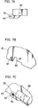
- the support frame of the image forming unit S has a front wall 65 which is formed with a projection 66 and a threaded hole 67 corresponding to the hole 62 and the oblong hole 64 respectively, as shown in Fig. 7B.
- the pre-transfer charger 17 is attached on the support frame of the image forming unit S as follows. First, the slide arm 53 on the rear plate 50 is placed in the slot 57 of the rear wall 54 of the support frame of the image forming unit. Thereafter, the pre-transfer charger 17 is moved rearward further while the slide arm 53 being supported at a lower end of the slot 57 until the projections 51, 52 on the rear plate 50 engage with the oblong holes 55, 56 formed in the rear wall 54 of the support frame.
- the hole 62 formed in the front-arranged driving box 60 engages with the projection 66 formed on the front wall of the support frame by pushing up a front portion of the pre-transfer charger 17. Consequently, the pre-transfer charger 17 is mounted on the support frame of the image forming unit S, and then fastened on the support frame by turning a screw 59 in the threaded hole 67 formed in the front wall 65 of the support frame through the oblong hole 64 of the attachment arm 63 on the driving box 60.
- the rear portion of the pre-transfer charger 17 is supported on the rear wall 54 of the support frame with the engagement of the projections 51, 52 and the holes 55, 56.
- the front portion of the pre-transfer charger 17 is supported on the front wall 65 of the support frame with the engagement of the projection 66 with the hole 62 and the screw 59.
- the pre-transfer charger 17 can be easily and firmly attached on the support frame. Accordingly, it will be seen that this arrangement makes it possible to easily replace a broken pre-transfer charger 17 with a new one without impairing the precise positional relationship between the guide portion 45 and the charging wire 71 of the pre-transfer charger 17 and the surface of the photosensitive drum 10 which is also supported on the support frame of the image forming unit S.
- the charging wire 71 is very thin and made of tungsten.
- the charging wire generates a corona discharge when being applied with a high voltage alternating current whose negative component is slightly greater than the positive component.
- the corona discharge electrically levels off the positively charged surface area of the photosensitive drum 10 on which a toner image is formed, and increases the negative electric level of the toner particles forming the toner image.
- a rear end of the charging wire 71 is connected with a spring 74 attached in a rear end block 73 provided in a rear end of the shield casing 72 while a front end of the charging wire 71 is fixedly secured to a metallic attachment member 75a in a front end block 75 provided in a front end of the shield casing 72.
- the front end of the charging wire 71 is secured on the attachment member 75a with use of a washer 76 and a screw 77.
- the charging wire 71 is stretched along a longitudinal direction of the shield casing 72.
- the screw 77 is connected to a high-voltage power source by way of a connector 88 as shown in Fig. 13.
- the rear and front end blocks 73 and 75 are attached with covers 78 and 79 to protect their respective internal constructions.
- a cleaning mechanism for cleaning the charging wire 71 will be described with reference to Figs. 11 to 13.
- the cleaning mechanism includes a movable member 81 and the cleaning member 32 attached on the movable member 81.
- the cleaning mechanism is adapted for removing dusts and other matter from the charging wire 71 to keep a uniform corona discharge.
- the movable member 81 comprises a slide block 811 and a holding boss 812 projecting from the slide block 811.
- the slide block 811 is slidably fitted in the guide opening 31c.
- the slide block 811 is formed with grooves in upper and lower end surfaces thereof. The grooves are engaged with an lower end of the vertical portion 31a and an upper end of the vertical portion 31b so that the slide block 811 is held between the vertical portions 31a and 31b. Consequently, the slide block 811 is movable along the stretched charging wire 71.
- the holding boss 812 is adapted for holding the cleaning member 32.
- the holding boss 812 is formed with a hollow portion in a center portion thereof and grooves 813. These grooves 813 are arranged in parallel with the extending direction of the charging wire 71.
- the cleaning member 32 includes a pair of contact members 32a and a clipping cover 32b.
- the contact member 32a are made of a sponge, soft synthetic resin or the like, and sandwiches the charging wire 71 therebetween.
- the pair of contact members 32a is inserted in the hollow portion of the holding boss 812 together with the clipping cover 32b.
- the movable member 81 is fixedly connected to an endless driving wire 82 by fastening members 83.
- the endless driving wire 82 is wound around a drive pulley 84 disposed in the driving box 60 and an unillustrated idle pulley disposed in the rear end portion of the shield casing 72.
- the drive pulley 84 is connected to a motor 86 through a worm gear mechanism 85.
- the motor 86 is connected with the power source by way of a connector 87.
- the drive pulley 84 is rotated by the motor 86 to move the driving wire 82. Consequently, the movable member 81 moves along the guide opening 31c and the cleaning member 32 moves along the extending direction of the charging wire 71 together with the movable member 81 to thereby clean the charging wire 71.
- the rotating direction of the motor 86 is changed to the reverse direction, and the movable member 81 is moved along the guide opening 31c in the reverse direc tion. While the movable member 81 being moved in the reverse direction, the cleaning member 32 cleans the charging wire 71 in the reverse direction. When the movable member 81 returns to the initial position, cleaning of the charging wire 71 is completed.
- an enclosure member 35 in the form of a tray is provided on an underside of the developing device 13.
- the enclosure member 35 has a specified depth to define an ozone removal duct.
- the enclosure member 35 and the underside of the developing device 13 forms a closed space except an inflow portion and an outflow portion 35a.
- the inflow portion 35a is air-tightly connected to a fan duct provided in a main body of the image forming apparatus.
- the fan duct is provided with a filter containing activated charcoal.
- the ozone removal duct is communicated with the pre-transfer charger 17 through the inflow portion. Specifically, the ozone removal duct is communicated with the chamber in which the charging wire 71 is stretched by way of the guide opening 31c and the upper opening 31d.
- the guide opening 31c serves as a vent for discharging the ozone from the charging wire chamber of the pre-transfer charger 17 as well as guiding the movable member 81 of the charging wire cleaning mechanism.
- a sponge 33 is attached on a top surface of the upper member 41, and comes into contact with an underside of the developing device 13 when the pre-transfer charger 17 is mounted on the image forming unit S as shown in Fig. 2.
- the sponge 33 keeps the ozone from leaking toward the photosensitive drum 10.
- a sealing strip 34 is attached on a top of the side member 42.
- the sealing strip 34 is made of a soft synthetic resin and brought into contact with the upper roller 241 of the registration roller pair 24 when the pre-transfer charger 17 is mounted on the image forming unit S, thereby keeping the ozone from leaking toward the registration roller pair 24.
- the ozone which occurs in the charging wire chamber of the pre-transfer charger 17 is efficiently removed through the ozone removal passage which is provided in such a limited small space. Consequently, a rise in the ozone concentration can be reliably prevented.
- the main charger 11 Upon the copying operation being started, the main charger 11 is driven to charge the photosensitive drum 10 at a specified level. A document placed on the contact glass 1 is illuminated by the exposure lamp 3. The reflected light is introduced by way of the reflecting mirrors 5, 6, and 7 to the lens unit 8, and then through the fixed mirror 9 to the charged surface of the photosensitive drum 10 to form an electrostatic latent image. Subsequently, the latent image on the photosensitive drum 10 is developed to a toner image by the developing device 13.
- a copy sheet is fed from the cassette 18 or 19 by the feed roller 20 or 21, and transported to the image forming assembly by the transport rollers 22, 23.
- the copy sheet is transported further to the space between the photosensitive drum 10 and the transferring device 14 by the registration roller pair 24. In this time, the copy sheet is guided to the space by the guide portion 45 formed on the pre-transfer charger 17.
- the copy sheet is applied with positive electric charge at a specified level by the transferring device 14 to electrically attract the toner image from the photosensitive drum 10. Subsequently, the copy sheet bearing the toner image is separated from the surface of the photosensitive drum 10 by the separating device 15. The copy sheet separated from the photosensitive drum 10 is transported downstream by the transport belt 26 up to the fixing device 27 where the toner image is fixed on the copy sheet. The copy sheet having the image fixed thereon is discharged to the tray 29 by the discharge roller pair 28.
Landscapes
- Physics & Mathematics (AREA)
- General Physics & Mathematics (AREA)
- Electrostatic Charge, Transfer And Separation In Electrography (AREA)
Applications Claiming Priority (2)
| Application Number | Priority Date | Filing Date | Title |
|---|---|---|---|
| JP19748893 | 1993-08-09 | ||
| JP197488/93 | 1993-08-09 |
Publications (2)
| Publication Number | Publication Date |
|---|---|
| EP0638852A2 true EP0638852A2 (de) | 1995-02-15 |
| EP0638852A3 EP0638852A3 (de) | 1995-04-05 |
Family
ID=16375310
Family Applications (1)
| Application Number | Title | Priority Date | Filing Date |
|---|---|---|---|
| EP94112358A Withdrawn EP0638852A3 (de) | 1993-08-09 | 1994-08-08 | Bilderzeugungsgerät mit einer Aufladevorrichtung vor der Übertragungsstation. |
Country Status (2)
| Country | Link |
|---|---|
| US (1) | US5481345A (de) |
| EP (1) | EP0638852A3 (de) |
Cited By (1)
| Publication number | Priority date | Publication date | Assignee | Title |
|---|---|---|---|---|
| EP0689106A3 (de) * | 1994-06-21 | 1997-04-16 | Mita Industrial Co Ltd | Zweiteiliger Schild für xerografische Aufladevorrichtung vor der Übertragung |
Families Citing this family (4)
| Publication number | Priority date | Publication date | Assignee | Title |
|---|---|---|---|---|
| JP2000075577A (ja) * | 1998-06-18 | 2000-03-14 | Canon Inc | 画像形成装置 |
| US6370354B1 (en) | 2000-08-08 | 2002-04-09 | Lexmark International, Inc. | Method and apparatus for controlling media-to-image registration of a single-pass intermediate transfer member-based printing apparatus |
| US7493559B1 (en) * | 2002-01-09 | 2009-02-17 | Ricoh Co., Ltd. | System and method for direct multi-modal annotation of objects |
| US8503901B2 (en) * | 2009-09-09 | 2013-08-06 | Konica Minolta Business Technologies, Inc. | Image forming apparatus with a toner contamination detecting device |
Family Cites Families (25)
| Publication number | Priority date | Publication date | Assignee | Title |
|---|---|---|---|---|
| US3784300A (en) * | 1971-12-23 | 1974-01-08 | Xerox Corp | Pre-transfer station |
| US3942006A (en) * | 1972-11-16 | 1976-03-02 | Xerox Corporation | Corona generator cleaning apparatus |
| US3978379A (en) * | 1974-11-20 | 1976-08-31 | Xerox Corporation | Corona generating device with an improved cleaning mechanism |
| US3965400A (en) * | 1975-02-24 | 1976-06-22 | Xerox Corporation | Corona generating device with improved built-in cleaning mechanism |
| JPS57104164A (en) * | 1980-12-19 | 1982-06-29 | Konishiroku Photo Ind Co Ltd | Electrophotographic method |
| US4482240A (en) * | 1981-06-24 | 1984-11-13 | Canon Kabushiki Kaisha | Electrophotographic process utilizing electrostatic separation and apparatus therefor |
| JPS58111054A (ja) * | 1981-12-25 | 1983-07-01 | Fuji Xerox Co Ltd | 電子写真に用いる感光体又は誘電体の帯電装置 |
| US4575221A (en) * | 1982-05-20 | 1986-03-11 | Canon Kabushiki Kaisha | Process kit and an image forming apparatus using the same |
| US4540268A (en) * | 1983-04-25 | 1985-09-10 | Canon Kabushiki Kaisha | Process kit and image forming apparatus using such kit |
| JPS59218467A (ja) * | 1983-05-26 | 1984-12-08 | Fuji Xerox Co Ltd | 複写機の帯電装置 |
| JPS60134263A (ja) * | 1983-12-22 | 1985-07-17 | Canon Inc | 画像形成装置 |
| US4952989A (en) * | 1985-04-16 | 1990-08-28 | Sharp Kabushiki Kaisha | Photoreceptor attachment device for an electrophotographic copying machine |
| JPH0690572B2 (ja) * | 1985-07-25 | 1994-11-14 | 富士ゼロックス株式会社 | 複写機の現像装置 |
| KR900009010B1 (ko) * | 1986-02-28 | 1990-12-17 | 미다 고오교오 가부시기가이샤 | 복사기 |
| JPH01107282A (ja) * | 1987-10-20 | 1989-04-25 | Nec Corp | 画像形成装置の転写帯電器 |
| JP2577409B2 (ja) * | 1987-11-30 | 1997-01-29 | 株式会社東芝 | 電子複写機 |
| US5012093A (en) * | 1988-08-29 | 1991-04-30 | Minolta Camera Co., Ltd. | Cleaning device for wire electrode of corona discharger |
| JPH0269790A (ja) * | 1988-09-06 | 1990-03-08 | Ricoh Co Ltd | 転写前処理装置 |
| JPH07109528B2 (ja) * | 1988-10-21 | 1995-11-22 | 三田工業株式会社 | コロナ放電器の放電ワイヤ清掃装置 |
| JPH02135386A (ja) * | 1988-11-16 | 1990-05-24 | Ricoh Co Ltd | 複写方法 |
| US5134443A (en) * | 1989-09-14 | 1992-07-28 | Mita Industrial Co., Ltd. | Conveying unit of image-forming machine |
| JPH0816810B2 (ja) * | 1989-09-29 | 1996-02-21 | キヤノン株式会社 | コロナ放電装置 |
| JP3090210B2 (ja) * | 1989-11-24 | 2000-09-18 | 富士ゼロックス株式会社 | 画像形成装置 |
| JPH03174550A (ja) * | 1989-12-04 | 1991-07-29 | Toshiba Corp | 画像形成装置 |
| US5128720A (en) * | 1991-01-18 | 1992-07-07 | Eastman Kodak Company | Device for collecting contamination products and ozone from a corona charger |
-
1994
- 1994-08-01 US US08/283,447 patent/US5481345A/en not_active Expired - Lifetime
- 1994-08-08 EP EP94112358A patent/EP0638852A3/de not_active Withdrawn
Cited By (1)
| Publication number | Priority date | Publication date | Assignee | Title |
|---|---|---|---|---|
| EP0689106A3 (de) * | 1994-06-21 | 1997-04-16 | Mita Industrial Co Ltd | Zweiteiliger Schild für xerografische Aufladevorrichtung vor der Übertragung |
Also Published As
| Publication number | Publication date |
|---|---|
| EP0638852A3 (de) | 1995-04-05 |
| US5481345A (en) | 1996-01-02 |
Similar Documents
| Publication | Publication Date | Title |
|---|---|---|
| US4286861A (en) | Electrostatic copying process and apparatus | |
| US20070077083A1 (en) | Developing cartridge detachable from image forming device | |
| JP2004091126A (ja) | 給紙カセットおよびそれを備えた画像形成装置 | |
| US4563076A (en) | Imaging apparatus | |
| JPH05119678A (ja) | 複式作動のブレード清掃装置 | |
| JPH06110337A (ja) | 画像形成装置 | |
| US5481345A (en) | Image forming apparatus provided with pre-transfer charger | |
| JP3156238B2 (ja) | 画像形成装置 | |
| EP0230033A2 (de) | Kassette zur Verwendung in einem Bilderzeugungsgerät | |
| EP1031889B1 (de) | Kombinierte Auflade- und Reinigungsklinge | |
| US4314018A (en) | Cleaning process for an electrostatic copying apparatus | |
| JP4282816B2 (ja) | カバー、プリントカートリッジ、及び電子写真プリント装置 | |
| JP3457775B2 (ja) | 電子写真装置 | |
| JPS6239434B2 (de) | ||
| JP7463857B2 (ja) | 仕分け装置およびそれを備えた画像形成装置 | |
| US7428392B2 (en) | Image forming apparatus, process cartridge and charger having a cleaning member | |
| JP2505713Y2 (ja) | 静電記録装置 | |
| JPH06130746A (ja) | 電子写真装置および電子写真装置用のプロセスユニット | |
| JPS5977450A (ja) | 転写型複写装置 | |
| JP2526254Y2 (ja) | 複写機のチャージャ装置 | |
| JP3577688B2 (ja) | 画像形成装置 | |
| JPS63292166A (ja) | プロセスカートリッジ及び前記プロセスカートリッジを着脱可能な画像形成装置 | |
| JPH0895343A (ja) | 画像形成装置 | |
| JPH07104588A (ja) | 画像形成装置 | |
| JP2778951B2 (ja) | 画像形成装置 |
Legal Events
| Date | Code | Title | Description |
|---|---|---|---|
| PUAI | Public reference made under article 153(3) epc to a published international application that has entered the european phase |
Free format text: ORIGINAL CODE: 0009012 |
|
| PUAL | Search report despatched |
Free format text: ORIGINAL CODE: 0009013 |
|
| AK | Designated contracting states |
Kind code of ref document: A2 Designated state(s): DE FR GB IT |
|
| AK | Designated contracting states |
Kind code of ref document: A3 Designated state(s): DE FR GB IT |
|
| 17P | Request for examination filed |
Effective date: 19950508 |
|
| GRAG | Despatch of communication of intention to grant |
Free format text: ORIGINAL CODE: EPIDOS AGRA |
|
| 17Q | First examination report despatched |
Effective date: 19961216 |
|
| STAA | Information on the status of an ep patent application or granted ep patent |
Free format text: STATUS: THE APPLICATION HAS BEEN WITHDRAWN |
|
| 18W | Application withdrawn |
Withdrawal date: 19970319 |