EP0635352B1 - Machine de moulage par soufflage - Google Patents
Machine de moulage par soufflage Download PDFInfo
- Publication number
- EP0635352B1 EP0635352B1 EP94110823A EP94110823A EP0635352B1 EP 0635352 B1 EP0635352 B1 EP 0635352B1 EP 94110823 A EP94110823 A EP 94110823A EP 94110823 A EP94110823 A EP 94110823A EP 0635352 B1 EP0635352 B1 EP 0635352B1
- Authority
- EP
- European Patent Office
- Prior art keywords
- blow
- block
- molding machine
- mold
- blow molding
- Prior art date
- Legal status (The legal status is an assumption and is not a legal conclusion. Google has not performed a legal analysis and makes no representation as to the accuracy of the status listed.)
- Expired - Lifetime
Links
Images


Classifications
-
- B—PERFORMING OPERATIONS; TRANSPORTING
- B29—WORKING OF PLASTICS; WORKING OF SUBSTANCES IN A PLASTIC STATE IN GENERAL
- B29C—SHAPING OR JOINING OF PLASTICS; SHAPING OF MATERIAL IN A PLASTIC STATE, NOT OTHERWISE PROVIDED FOR; AFTER-TREATMENT OF THE SHAPED PRODUCTS, e.g. REPAIRING
- B29C49/00—Blow-moulding, i.e. blowing a preform or parison to a desired shape within a mould; Apparatus therefor
- B29C49/42—Component parts, details or accessories; Auxiliary operations
- B29C49/58—Blowing means
-
- B—PERFORMING OPERATIONS; TRANSPORTING
- B29—WORKING OF PLASTICS; WORKING OF SUBSTANCES IN A PLASTIC STATE IN GENERAL
- B29C—SHAPING OR JOINING OF PLASTICS; SHAPING OF MATERIAL IN A PLASTIC STATE, NOT OTHERWISE PROVIDED FOR; AFTER-TREATMENT OF THE SHAPED PRODUCTS, e.g. REPAIRING
- B29C31/00—Handling, e.g. feeding of the material to be shaped, storage of plastics material before moulding; Automation, i.e. automated handling lines in plastics processing plants, e.g. using manipulators or robots
- B29C31/006—Handling moulds, e.g. between a mould store and a moulding machine
-
- B—PERFORMING OPERATIONS; TRANSPORTING
- B29—WORKING OF PLASTICS; WORKING OF SUBSTANCES IN A PLASTIC STATE IN GENERAL
- B29C—SHAPING OR JOINING OF PLASTICS; SHAPING OF MATERIAL IN A PLASTIC STATE, NOT OTHERWISE PROVIDED FOR; AFTER-TREATMENT OF THE SHAPED PRODUCTS, e.g. REPAIRING
- B29C49/00—Blow-moulding, i.e. blowing a preform or parison to a desired shape within a mould; Apparatus therefor
- B29C49/42—Component parts, details or accessories; Auxiliary operations
- B29C49/78—Measuring, controlling or regulating
-
- B—PERFORMING OPERATIONS; TRANSPORTING
- B29—WORKING OF PLASTICS; WORKING OF SUBSTANCES IN A PLASTIC STATE IN GENERAL
- B29C—SHAPING OR JOINING OF PLASTICS; SHAPING OF MATERIAL IN A PLASTIC STATE, NOT OTHERWISE PROVIDED FOR; AFTER-TREATMENT OF THE SHAPED PRODUCTS, e.g. REPAIRING
- B29C49/00—Blow-moulding, i.e. blowing a preform or parison to a desired shape within a mould; Apparatus therefor
- B29C49/42—Component parts, details or accessories; Auxiliary operations
- B29C49/48—Moulds
- B29C2049/4856—Mounting, exchanging or centering moulds or parts thereof
-
- B—PERFORMING OPERATIONS; TRANSPORTING
- B29—WORKING OF PLASTICS; WORKING OF SUBSTANCES IN A PLASTIC STATE IN GENERAL
- B29C—SHAPING OR JOINING OF PLASTICS; SHAPING OF MATERIAL IN A PLASTIC STATE, NOT OTHERWISE PROVIDED FOR; AFTER-TREATMENT OF THE SHAPED PRODUCTS, e.g. REPAIRING
- B29C49/00—Blow-moulding, i.e. blowing a preform or parison to a desired shape within a mould; Apparatus therefor
- B29C49/42—Component parts, details or accessories; Auxiliary operations
- B29C49/58—Blowing means
- B29C2049/5893—Mounting, exchanging or centering blowing means
-
- B—PERFORMING OPERATIONS; TRANSPORTING
- B29—WORKING OF PLASTICS; WORKING OF SUBSTANCES IN A PLASTIC STATE IN GENERAL
- B29C—SHAPING OR JOINING OF PLASTICS; SHAPING OF MATERIAL IN A PLASTIC STATE, NOT OTHERWISE PROVIDED FOR; AFTER-TREATMENT OF THE SHAPED PRODUCTS, e.g. REPAIRING
- B29C33/00—Moulds or cores; Details thereof or accessories therefor
- B29C33/30—Mounting, exchanging or centering
- B29C33/303—Mounting, exchanging or centering centering mould parts or halves, e.g. during mounting
- B29C33/304—Mounting, exchanging or centering centering mould parts or halves, e.g. during mounting centering cores
-
- B—PERFORMING OPERATIONS; TRANSPORTING
- B29—WORKING OF PLASTICS; WORKING OF SUBSTANCES IN A PLASTIC STATE IN GENERAL
- B29C—SHAPING OR JOINING OF PLASTICS; SHAPING OF MATERIAL IN A PLASTIC STATE, NOT OTHERWISE PROVIDED FOR; AFTER-TREATMENT OF THE SHAPED PRODUCTS, e.g. REPAIRING
- B29C49/00—Blow-moulding, i.e. blowing a preform or parison to a desired shape within a mould; Apparatus therefor
- B29C49/02—Combined blow-moulding and manufacture of the preform or the parison
- B29C49/04—Extrusion blow-moulding
-
- B—PERFORMING OPERATIONS; TRANSPORTING
- B29—WORKING OF PLASTICS; WORKING OF SUBSTANCES IN A PLASTIC STATE IN GENERAL
- B29C—SHAPING OR JOINING OF PLASTICS; SHAPING OF MATERIAL IN A PLASTIC STATE, NOT OTHERWISE PROVIDED FOR; AFTER-TREATMENT OF THE SHAPED PRODUCTS, e.g. REPAIRING
- B29C49/00—Blow-moulding, i.e. blowing a preform or parison to a desired shape within a mould; Apparatus therefor
- B29C49/42—Component parts, details or accessories; Auxiliary operations
- B29C49/42378—Handling malfunction
- B29C49/42382—Stopping at least a part of the machine
-
- B—PERFORMING OPERATIONS; TRANSPORTING
- B29—WORKING OF PLASTICS; WORKING OF SUBSTANCES IN A PLASTIC STATE IN GENERAL
- B29C—SHAPING OR JOINING OF PLASTICS; SHAPING OF MATERIAL IN A PLASTIC STATE, NOT OTHERWISE PROVIDED FOR; AFTER-TREATMENT OF THE SHAPED PRODUCTS, e.g. REPAIRING
- B29C49/00—Blow-moulding, i.e. blowing a preform or parison to a desired shape within a mould; Apparatus therefor
- B29C49/42—Component parts, details or accessories; Auxiliary operations
- B29C49/42407—Procedures for start-up or material change
- B29C49/4241—Material change
-
- B—PERFORMING OPERATIONS; TRANSPORTING
- B29—WORKING OF PLASTICS; WORKING OF SUBSTANCES IN A PLASTIC STATE IN GENERAL
- B29C—SHAPING OR JOINING OF PLASTICS; SHAPING OF MATERIAL IN A PLASTIC STATE, NOT OTHERWISE PROVIDED FOR; AFTER-TREATMENT OF THE SHAPED PRODUCTS, e.g. REPAIRING
- B29C49/00—Blow-moulding, i.e. blowing a preform or parison to a desired shape within a mould; Apparatus therefor
- B29C49/42—Component parts, details or accessories; Auxiliary operations
- B29C49/4284—Means for recycling or reusing auxiliaries or materials, e.g. blowing fluids or energy
-
- B—PERFORMING OPERATIONS; TRANSPORTING
- B29—WORKING OF PLASTICS; WORKING OF SUBSTANCES IN A PLASTIC STATE IN GENERAL
- B29K—INDEXING SCHEME ASSOCIATED WITH SUBCLASSES B29B, B29C OR B29D, RELATING TO MOULDING MATERIALS OR TO MATERIALS FOR MOULDS, REINFORCEMENTS, FILLERS OR PREFORMED PARTS, e.g. INSERTS
- B29K2105/00—Condition, form or state of moulded material or of the material to be shaped
- B29K2105/26—Scrap or recycled material
-
- Y—GENERAL TAGGING OF NEW TECHNOLOGICAL DEVELOPMENTS; GENERAL TAGGING OF CROSS-SECTIONAL TECHNOLOGIES SPANNING OVER SEVERAL SECTIONS OF THE IPC; TECHNICAL SUBJECTS COVERED BY FORMER USPC CROSS-REFERENCE ART COLLECTIONS [XRACs] AND DIGESTS
- Y02—TECHNOLOGIES OR APPLICATIONS FOR MITIGATION OR ADAPTATION AGAINST CLIMATE CHANGE
- Y02P—CLIMATE CHANGE MITIGATION TECHNOLOGIES IN THE PRODUCTION OR PROCESSING OF GOODS
- Y02P70/00—Climate change mitigation technologies in the production process for final industrial or consumer products
- Y02P70/10—Greenhouse gas [GHG] capture, material saving, heat recovery or other energy efficient measures, e.g. motor control, characterised by manufacturing processes, e.g. for rolling metal or metal working
-
- Y—GENERAL TAGGING OF NEW TECHNOLOGICAL DEVELOPMENTS; GENERAL TAGGING OF CROSS-SECTIONAL TECHNOLOGIES SPANNING OVER SEVERAL SECTIONS OF THE IPC; TECHNICAL SUBJECTS COVERED BY FORMER USPC CROSS-REFERENCE ART COLLECTIONS [XRACs] AND DIGESTS
- Y10—TECHNICAL SUBJECTS COVERED BY FORMER USPC
- Y10S—TECHNICAL SUBJECTS COVERED BY FORMER USPC CROSS-REFERENCE ART COLLECTIONS [XRACs] AND DIGESTS
- Y10S425/00—Plastic article or earthenware shaping or treating: apparatus
- Y10S425/806—Flash removal
Definitions
- the present invention relates to a method of controlling a blow molding machine from a completion of production of one product to a start of production of a next product and a blow molding machine having means for controlling the blow molding machine between a completion of production of one product and a start of production of the next product.
- the blow molding machine is a machine which serves to make resin hollow moldings in accordance with the shape of a cavity formed in a mold held by a mold clamping unit. Upon molding operation, parisons as supplied from an extruder are received in the mold, and subjected to an air blow out of a calibrating unit.
- the blow molding machine can continuously be operated by automatic control from a start of production of one product to a completion of production thereof, however, it cannot automatically carry out a preparation from a completion of production of one product to a start of production of a next product.
- the first mentioned objective is solved by a method of controlling a blow molding machine from a completion of production of one product of a resin to a start of production of a next product according to claim 1.
- a blow molding machine having means for controlling the blow molding machine between a completion of production of one product and a start of production of a next product according to claim 7.
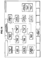
- a temperature control means 100 which controls, after completing a predetermined production amount during a molding operation of a blow molding machine, a programmed temperature decrease and a programmed temperature increase in accordance with a next product data.
- a blow molding machine operation control means 101 which controls a stop of an extruding screw after pressing out the resin therein, a read of a next product data, a drainage of a mold which has finished the production, a detaching of a blow pin unit, a mounting of a transport jig, a detaching of the mold by the transport jig, a detaching of the die and core, a mounting of the die and core for the next product, a mounting of the mold for the next product, a detaching of the transport jig, a mounting of the blow pin unit for the next product, a centering of the blow pin, and a returning of a calibrating unit to the origin.
- a jig exchange control means 102 is provided which controls a sequent transport of the mold, die, core, and blow pin unit for the next product and the mold, die, core, and blow pin unit to be changed to predetermined optimum positions in accordance with predetermined motions of the transport jig.
- a resin control means 103 is provided which controls a resin change command in accordance with a stop of a resin supply and the next product data.
- a global control means 104 which controls the control means 100 to 103 so as to start the production of the next product when all operation conditions in the control means 100 to 103 are satisfied.
- the control means 100, 103 can easily be formed in the known blow molding machine by applying the known art thereto, whereas the control means 101, 102, 104 cannot be formed in the known blow molding machine. Therefore, it is necessary to improve the blow molding machine.
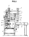
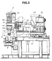
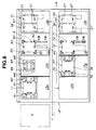
- an extruder 2 is mounted on a base 1 of the blow molding machine to be movable upward and downward at a predetermined stroke with respect to a mold 4 which is fixed to a mold clamping unit 3 as movably arranged.
- a die 2a is detachably arranged to the extruder 2 at the lowest portion thereof by a screw or the like, whereas a core 2b is detachably arranged in the die 2a by a screw or the like.
- Parisons having a predetermined thickness which are formed by a combination of the die 2a and the core 2b are pressed out downward, and received in the mold 4 fixed to the mold clamping unit 3.
- an extruder cylinder 2c for melting the resin to produce the parisons a hopper 2d for supplying the resin thereto, and a motor 2e for rotating an extruding screw in the extruder cylinder 2c are disposed behind the exturder 2 in the same way as the conventional blow molding machine.
- a calibrating unit 5 is disposed adjacent to the extruder 2.
- rails 6 are mounted on the base 1, and a support 7 is slidably disposed on the rails 6.
- the support 7 is formed with a vertical wall 7a having a front face on which rails 8 are mounted in the direction perpendicular to the rails 6.
- An arm 9 is horizontally movably supported on the rails 8 so as to fix the calibrating unit 5.
- the calibrating unit 5 is movable in the longitudinal direction of the base 1 as viewed in Fig. 4 along the rails 6 and in the cross direction of the base 1 as viewed in Fig. 4 along the rails 8.
- the calibrating unit 5 has a calibrating head 10 which is movable upward and downward with respect to the mold 4.
- a motion of the calibrating unit 5 is automatically controlled in a three-dimensional direction: A motion in the vertical direction is carried out by driving a ball screw 5b in the normal and reverse directions by a servo motor 5a, and a motion in the longitudinal and cross directions is carried out by servo motors 5c, 5d, etc.
- a blow pin unit 11 is detachably mounted to the calibrating head 10 of the calibrating unit 5.
- the calibrating head 10 has a lower portion with an inner ceiling in which a dovetail groove 10a having connection ports for air and water pipes (not shown) is formed, one of blocks defining the dovetail groove 10a being constructed to be vertically movable, thus obtaining a chuck 10b for holding and releasing the blow pin unit 11 through an air cylinder, etc.
- the blow pin unit 11 includes an insert portion 11a with a trapezoid section, which is engaged with the dovetail groove 10a and has a lower portion to which a pair of blow pins 11b and a stripper plate 11c are mounted.
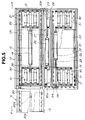
- a jig exchange table 12 is disposed on the right side of the base 1 horizontally and at a predetermined level. As shown in Fig. 4, seven palettes 13 (13a-13g) are arranged on the jig exchange table 12 lengthwise and crosswise so as to secure a vacancy 12a for one palette, the palettes 13a-13g being capable of circulating on a horizontal plane of the jig exchange table 12.
- the palettes 13 are carriers which serve to transport in sequence the mold, molding jigs, etc. disposed thereon to predetermined positions: a blow pin unit bed 40 on the palette 13a, a transport jig 43 and its bed 46 on the palette 13b, a mold bed 50 on the palette 13c, die and core detaching jigs 51, 52 on the palette 13d, die and core mounting jigs 55, 56 on the palette 13e, an exchange mold 71 and its bed 70 on the palette 13f, and an exchange blow pin unit 77 and its bed 75 on the palette 13g.
- the jig exchange table 12 includes a table main body 14 on which a movable frame 15 and a stationary frame 16 disposed, each frame being formed in a rectangular shape.
- the movable frame 15 is movable in the longitudinal direction through rollers 18 arranged at a bottom thereof which are rotated on rails 17 disposed on the table main body 14.
- the stationary frame 16 is appropriately fixed on the table main body 14.
- a fluid (hydraulic or air) cylinder 19 is fixed to the movable frame 15 in a lower portion thereof, and includes a piston rod 20 connected to the movable frame 15 at a short inner side thereof through a bracket 20a and a rod 20b secured thereto.
- the movable frame 15 which is reciprocative in the longitudinal direction, is moved to a front side as indicated by an arrow F in Figs. 5 and 6 from the table main body 14 at a stroke of one palette, forming a delivery station S of the jigs, etc. to the calibrating unit 5.
- a roller conveyer is constructed so that a plurality of rollers 21 are rotatably horizontally supported to the movable frame 15 and the stationary frame 16 at long inner sides thereof at predetermined intervals in the longitudinal direction.
- the palettes 13 are disposed on the rollers 21.
- the palettes 13 are moved by rotation of the rollers 21 in the longitudinal direction of the movable frame 15 or the stationary frame 16, respectively.
- a fluid cylinder 22 is fixed on the table main body or under the palettes 13 in the stationary frame 16, and a bracket 24 is connected to an end of a piston rod 23 which is movable forward and backward by the cylinder 22.
- a vertical push rod 25 extending upward is supported to the bracket 24 to be capable of abutting on a side of the palette 13.
- a fluid cylinder 26 is fixed to the table main body 14 or under the palettes 13 between the movable frame 15 and the stationary frame 16 and on the long side of the movable frame 15, and a bracket 28 is connected to an end of a piston rod 27 which is movable forward and backward by the cylinder 26.
- a hook-shaped vertical push plate 29 extending upward is supported to the bracket 24 to be capable of abutting on a side of the palette 13.
- the palettes 13 can be moved to a rear side as indicated by an arrow R in Figs. 5 and 6 since the piston rod 23 is pulled into the cylinder 22 to contact the push rod 25 to the side of the palette 13.
- the palettes 13 can be moved to the front side F in Figs. 5 and 6 since the piston rod 27 is pulled into the cylinder 26 to contact the push plate 29 to the side of the palette 13.
- the push rod 25 and the push plate 29 are disposed in a position wherein they are not an obstacle when the palettes 13 are moved from the movable frame 15 to the stationary frame 16 and vice versa.
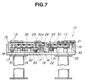
- a plurality of bases 31 for supporting motor rollers 30 located below the rollers 21 are arranged at both ends of the movable frame 15 and the stationary frame 16 in the longitudinal direction thereof so as to be movable upward and downward.
- the motor rollers 30 have an independent drive source, and are rotatable, respectively.
- Each base 31 is horizontally connected to piston rods 33 at a head thereof to be movable upward and downward, each piston rod 33 being movable forward and backward by a fluid cylinder 32 fixed on the table main body 14.
- At least one motor roller 30a is interposed between the movable frame 15 and the stationary frame 16, and arranged above the rollers 21.
- the motor roller 30a has the same constitution as the motor rollers 30, and serves as an intermediary when passing the palettes 13 transported by the motor rollers 30 from the movable frame 15 to the stationary frame 16 and vice versa.
- the palette 13 as disposed on the rollers 21 are separated therefrom, and supported by the motor rollers 30.
- the palette 13 is moved by the motor rollers 30, 30a from the movable frame 15 to the stationary frame 16 at a front end of the front side F, and from the stationary frame 16 to the movable frame 15 at a rear end of the rear side R as shown in Figs. 5 and 6.
- blow pin unit bed 40 the transport jig 43 and its bed 49, the mold bed 50, the die and core detaching jigs 51, 52, the die and core mounting jigs 55, 56, the exchange mold 71 and its bed 70, and the exchange blow pin unit 77 and its bed 75, which are disposed on the palettes 13.
- the blow pin unit bed 40 is a support arranged on the palette 13a and having an upper side and right and left sides opened, which includes two L-shaped reinforced members 41 arranged opposite to each other with a predetermined distance, and serves to support the blow pin unit 11 which is actually in use by insertion between the members 41.
- the transport jig 43 includes an insert portion 44 which is engaged with the dovetail groove 10a and locked by the chuck 10b, and has both sides as viewed in the cross direction in Fig. 8 to which hands 45 are swingably connected.
- the insert portion 44 has an upper side formed with the air supply ports 46 which communicate with air supply ports having openings in the inner ceiling of the calibrating head 10.
- the hands 45 can be opened and closed by a fluid cylinder 47 driven by fluid or air supplied through the air supply ports 46 which allow fluid communication between the insert portion 44 and the calibrating head 10.
- Pins 48 are arranged to the hands 45 at lower ends thereof and on the sides opposite to each other.
- the transport jig bed 49 is an U-shaped support arranged on the palette 13b and an upper side and right and left sides opened, and serves to support the transport jig 43 by insertion between two members in the same way as the blow pin unit bed 40.
- the mold bed 50 includes L-shaped stoppers arranged on the palette 13c, which serve to fix four corners of the mold 4 as actually mounted to the mold clamping unit 3. Both sides of the mold 4 are held by the hands 45, each side being formed with holes 4a for receiving the pins 48 of the hand 45.
- the die and core detaching jigs 51, 52 include a die detaching jig 51 and a core detaching jig 52 constructed independently, which are disposed on the same palette 13d.
- the die and core mounting jigs 55, 56 include a die mounting jig 55 and a core mounting jig 56 constructed independently, which are disposed on the same palette 13e.
- Arranged on upper sides of the die and core detaching jigs 51, 52 and the die and core mounting jigs 55, 56 are arms 57 which protrude vertically, each having sides formed with holes 58 for receiving the pins 48 of the hand 45.
- the die and core detaching jigs 51, 52 are apparatus which serve to disengage from the extruder 2 the die 2a and core 2b which are actually in use, whereas the die and core mounting jigs 55, 56 are apparatus which serve to engage the die and core for the next product with the extruder 2.
- the die and core detaching jigs 51, 52 and the die and core mounting jigs 55, 56 include an air cylinder, respectively, which rotates a rotary member biting the die or core to carry out a detaching and mounting operation.
- Air supply is carried out by the mold clamping unit 3.
- the rotary member may be driven by an electric motor with a battery.
- Fig. 11 shows a front constitution of the die detaching jig 51 and the die mounting jig 55
- Fig. 12 shows a front constitution of the core detaching jig 52 and the core mounting jig 56
- Fig. 13 shows a plane constitution of the die and core detaching jigs 51, 52 and the die and core mounting jigs 55, 56.
- Each gear 60 has a center portion formed with a hexagonal shaft hole 60a as shown in Fig. 13, through which a slidable power transmission shaft 65 of, e.g., the hexagonal section type or the spline type is arranged to be moved upward and downward, and has an upper end to which a die engaged portion 66 is connected coaxially.
- the die engaged portion 66 is in the form of a concave, and has an inner peripheral face on which pins 66a are horizontally oppositely arranged in the diametrical direction.
- An outer peripheral face of the die 2a is formed with concavities engaged with the pins 66a.
- an exposed head 66c having the form of a hexagonal convex is rotatably arranged above the power transmission shaft 65 in the axial direction thereof as shown in Fig. 12.
- a lower center portion of the core 2b is formed with a hexagonal concave with which the head 66c is engaged.
- the pin 66a or head 66c is engaged with the concave thereof to allow rotation of the die 2a or core 2b.
- a spring 66b is arranged in a lower portion of the die engaged portion 66 to be individually movable upward and downward.
- the core engaged portion has the same construction.
- a plate 68 is arranged at upper ends of four piston rods 67a which are retractile from a pair of fluid cylinders 67 arranged at the side of the arms 57, and a pair of die engaged portions 66 or a pair of heads 66c is rotatably disposed thereon.
- the fluid cylinders 67 are of the unit type including a pair of cylinders.
- An air supply block 69 is mounted to the plate 59a on a lower side thereof so as to supply air to the fluid cylinders 64, 67.
- the air supply block 69 has an air supply port 69a which communicates with an air supply port (not shown) arranged in the mold clamping unit 3 when the die and core detaching jigs 51, 52 or the die and core mounting jigs 55, 56 are mounted to the mold clamping unit 3, so that air is distributed from the air supply port 69a to the fluid cylinders 64, 67 through pipe.
- each torque limiter 90 is integrally formed with the gear 60, and races when the gear 60 undergoes over a predetermined tightening torque, preventing a unnecessary tightening of the die 2a or core 2b. As is not shown, the torque limiter 90 is also arranged to the die mounting jig 55.
- the exchange mold bed 70 which is approximately the same as the mold bed 50, includes hook-shaped stoppers arranged on the palette 13f, which serve to fix four corners of the mold 71 for the next product, thus securely supporting the mold 71 on the exchange mold bed 70. Both sides of the mold 71 are held by the hands 45, each side being formed with holes 72 for receiving the pins 48 of the hand 45.
- the exchange blow pin unit bed 75 is a support arranged on the palette 13g and having an upper side and right and left sides opened, which includes two L-shaped members 76 arranged opposite to each other with a predetermined distance, and serves to support the blow pin unit 77 for the next product by insertion between the members 76.
- the blow pin unit 77 is the same as the blow pin unit 11 which is actually in use, and has an insert portion 78 provided with connection ports which communicate with the air and water pipes of the calibrating unit 10.
- detection means such as a limit switch, sensor, etc. for detecting positions of the extruder 2, the mold clamping unit 3, the calibrating unit 5, and the jig exchange table 12 which are operated for a jig exchange as well as safety means for confirming the detection means.
- Fig. 14 an automatic exchange of the mold and molding jigs will be described.
- the extruder 2 is stopped after pressing out the resin therein, and an automatic jig exchange preparation is carried out. Then, the control means 101 reads a data necessary to the next product.
- a drainage of the mold 4 which is in use is carried out, then a detaching of the blow pin unit 11 which is in use is started.
- the support 7 is withdrawn from above the mold 4 along the rails 6, then the calibrating unit 5 is moved rightward as viewed in Fig. 2 or to the jig exchange table 12 along the rails 8.
- the jig exchange table 12 already moves the movable frame 15 to the front side F by operation of the cylinder 19, having a protrusion corresponding to one palette 13 from the stationary frame 16.
- the blow pin unit bed 40 as disposed on the palette 13a is positioned in the delivery station S.
- the movable frame 15 is withdrawn to be in line with the stationary frame 16, and the palette 13a as disposed on the blow pin unit bed 40 is moved to the vacancy 12a on the stationary frame 16 as shown in Fig. 8.
- the palette 13a is separated from the rollers 21, and supported by the motor rollers 30.
- the palette 13a is moved from the movable frame 15 to the stationary frame 16, obtaining a vacant space at the front end of the movable frame 15.
- the subsequent palettes 13b-13g on the jig exchange table 12 are transported one by one to the front end of the movable frame 15, and the palettes 13b-13g as located at the front end of the movable frame 15 are transported to the stationary frame 16. Therefore, the palettes 13a-13g can be circulated on the jig exchange table 12 by a circulation means which comprises the cylinders 19, 22, 26 and the motor rollers 30, 30a.
- the cylinder 19 is operated to press the movable frame 15 to the front side F, locating the transport jig 43 in the delivery station S.
- the waiting calibrating unit 5 is moved to the transport jig 43 so that the insert portion 44 of the transport jig 43 is engaged with the dovetail groove 10a.
- the chuck 10b is operated to mount the transport jig 43 to the calibrating head 10, allowing a fluid communication of the air supply ports 46, obtaining the hands 45 which is in the operable state.
- the calibrating unit 5 having the transport jig 43 mounted is returned to the initial calibrating position.
- the mold clamping unit 3 holding the mold 4 which is in use is operated to position the mold 4 just under the calibrating unit 5, and have a wait for a detaching of the mold 4.
- the mold clamping unit 3 may be operated upon molding in the same way as the conventional method.
- the calibrating unit 5 disposes the mold 4 on the mold bed 50 on the palette 13c subsequent to the front end of the movable frame 15 which is positioned in the delivery station S. In the vicinity of the jig exchange table 12, the calibrating unit 5 has a wait for a next holding operation with the transport jig 43 mounted.
- the mold bed 50 having the mold 4 thereon is transported to the stationary frame 16 in the way as described above, and the palettes 13d having the die and core detaching jigs 51, 52 thereof is transported to the front end of the movable frame 15. Moreover, the movable frame 15 is moved to the front side F so as to position the palette 13d in the delivery station S.
- the waiting calibrating unit 5 For mounting the die and core detaching jigs 51, 52 in the delivery station S, the waiting calibrating unit 5 approaches the die detaching jig 51, which is held through the transport jig 43, and transported in the way as described above, then fixed to the mold clamping unit 3. As best seen in Fig. 2, the mold clamping unit 3 is moved below the extruder 2, and part of the die detaching jig 51 is moved upward or to the extruder 2 so as to hold, rotate and remove the die 2a.
- Part of the die detaching jig 51 holding the die 2a as removed is moved downward, and the die detaching jig 51 is returned to the initial state.
- the mold clamping unit 3 is also returned to the initial state, and positioned below the calibrating unit 5.
- the die detaching jig 51 is held and moved upward by the calibrating unit 5 through the hands 45 of the transport jig 43, and returned to the initial position on the jig exchange table 12.
- the core detaching jig 52 is held by the transport jig 43, and transported to the mold clamping jig 3 for fixing.
- the core detaching jig 52 is moved below the extruder 2 by the mold clamping unit 3, and part of the core detaching jig 52 is moved upward to hold, rotate and remove the exposed core 2b.
- the mold clamping unit 3 When part of the core detaching jig 52 holding the core 2b as removed is moved downward or to the initial state, the mold clamping unit 3 is returned to the initial state, and positioned below the calibrating unit 5.
- the core detaching jig 52 is held and moved upward by the calibrating unit 5 through the hands 45 of the transport jig 43, and returned to the initial position on the jig exchange table 12 for a wait.
- the die detaching jig 51 holding the die 2a and the core detaching jig 52 holding the core 2b are transported to the stationary frame 16 in the way as described above.
- the palette 13e having the die and core mounting jigs 55, 56 thereon is transported to the front end of the movable frame 15, which is moved to the front side F so as to position the palette 13e in the delivery station S.
- the die and core mounting jigs 55, 56 are transported to the mold clamping unit 3 for fixing so as to mount the die and core for the next product to the extruder 2.
- the palette 13e having the die and core mounting jigs 55, 56 thereon is transported to the stationary frame 16 in the same way as described above.
- the palette 13f having the mold bed 70 supporting the mold 71 for the next product is transported to the front end of the movable frame 15, which is moved to the front side F so as to position the mold 71 in the delivery station S.
- the mold 71 is held by the transport jig 43 of the calibrating unit 5, which is moved to fix the mold 71 to the mold clamping unit 3. Meanwhile, the movable frame 15 is withdrawn to be in line with the stationary frame 16.
- the palettes 13f, 13g, 13a are transported to the stationary frame 16, and the palette 13b is positioned at the front end of the movable frame 15.
- the calibrating unit 5 is returned to the jig exchange table 12 so as to dispose the transport jig 43 on the transport jig bed 46 on the palette 13b moved at the front end of the movable frame 15, and has a wait.
- the palette 13g having the blow pin unit 77 to be changed is moved to the front end of the movable frame 15, which is moved so as to position the blow pin unit 77 in the delivery station S.
- the calibrating unit 5 is moved to the jig exchange table 12 so as to insert the insert portion 78 of the blow pin unit 77 into the dovetail groove 10a of the calibrating head 10, obtaining a fluid communication of the air and water supply pipes, and an operation and lock of the chuck 10b.
- the calibrating unit 5 is returned to the blowing position where it faces the mold clamping unit 3.
- a positional adjustment of the calibrating unit 5 i.e., a centering of the blow pins 11b of the calibrating unit 5 returned to the blowing position with blow ports of the mold 71 fixed to the mold clamping unit 3, a preparation for the next product is completed.
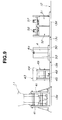
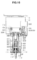
- locking blocks 504, 505 are arranged to form the dovetail groove 10a in the calibrating head or first block 10 which is vertically movably arranged in connection with the arm 9.
- the locking block 504 is fixed to the calibrating head 10, whereas the locking block 505 is hung to be vertically movable through an air cylinder 506 fixed to the calibrating head 10, forming the chuck 10b.
- the insert portion or second block 11a having substantially the form of a trapezoid and engaged with the dovetail groove 10a.
- a center block or third block 509 and right and left cylinders 510 are vertically connected thereto through bolts 508.
- the cylinders 510 are supported by the center block 509 in side portions thereof as shown in Fig. 17, and the stripper plate 11c is horizontally connected to piston rods 511 at lower ends thereof.
- the center block 509 is formed with a pair of cylinder chambers 513 in the positions corresponding to the piston rods 511, and nozzle bodies 515 each connected to the blow pin 11b are vertically movably received therein.
- the blow pin 11b is arranged through a stripper bush or centering member 516 fixed to the stripper plate 11c so as to extend downward.
- a cylinder 518 is connected to the nozzle body 515 at an upper end thereof through a piston rod 517, and filled with a fluid such as oil or grease via a communication passage 520 formed in the center block 509.
- the communication passage 520 allows a fluid communication between the pair of cylinder chambers 513, which serves to operate both cylinders 518 together.
- a manifold 521 is fixed to the nozzle body 515 in an upper portion thereof so as to face a plurality of discharge ports 522 formed in an inner wall of the cylinder 513, respectively.
- the discharge ports 522 are openings of passages 523 formed in the center block 513, each passage 523 having an opening at an upper face of the insert portion 11a.
- the calibrating head 10 is formed with passages 524, each having an opening corresponding to the passage 523.
- the passages 523, 524 which serve to discharge air and cooling water, have an opening to the manifold 521, respectively, so as to communicate with a passage in the nozzle body 515.
- An O-ring is interposed between the openings of the passages 523, 524 for sealing.
- Circulation passages are provided for air and cooling water.
- a plurality of belleville springs 525 are arranged on the side of a lower end of the nozzle body 515, and received in the cylinder chamber 513, and supported by an end plate 526 through which the blow pin 11b is vertically movably arranged.
- the locking block 505 is moved downward by drive of the air cylinder 506 to enlarge the dovetail groove 10a.
- the insert portion 11a is slid into and engaged with the dovetail groove 10a so that the passages 523, 524 correspond to each other.
- the locking block 505 is moved upward by drive of the air cylinder 506 to contract the dovetail groove 10a, tightly fixing the insert portion 11a to the calibrating head 10.
- the mold 4 holding the parisons and fixed to the mold clamping unit 3 is moved to be stationarily positioned under the blow pins 11, then the calibrating head 10 is moved downward to insert the blow pins 11b into openings of cutting plates 431 of the mold 4, making cutting sleeves 11d of the blow pins 11b contact a cutting plates 431, respectively.
- the piston rod 517 of the other cylinder 518 is moved downward to press down the nozzle body 515, pressing the blow pin 11b into the mold 4 so as to correctly contact the cutting sleeve 11d with the cutting plate 431.
- an automatic adjustment of both blow pins 11b is carried out, and the cutting sleeves 11d are pressed against the cutting plates 431 by an equal force so as to cut flashes 200, respectively.
- the calibrating head 10 After being slightly moved upward to separate the cutting sleeve 11d from the cutting plate 431, the calibrating head 10 is moved upward again, which causes an upward movement of the blow pin 11b with the flash 200 stuck thereto.
- the stripper plate 11c is moved downward, thus dropping the flash 200 through the stripper bush 516.
- the flash 200 as fully cooled is suitably eliminated without any bad influence on a product 533 such as a sticking and any dispersion in all directions.
- the stripper bush 516 is a conical tubular body which is fixed to the stripper plate 11c so as to support the blow pin 11b arranged therethrough, and has a lower outer peripheral face protruding from the stripper plate 11c or a conical outer peripheral face 501.
- the conical outer peripheral face 501 is a face parallel to a conical inner peripheral face 432 of the cutting plate 431.
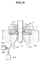
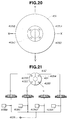
- the cutting plate 431 is formed with a plurality of blowout openings 405A-405D, every couple thereof facing each other in the diametrical direction.
- Each blowout opening 405A-405D is arranged in the conical inner peripheral face 432 of the cutting plate 431 as shown in Fig. 19.
- two servo motors or actuators 619, 620 are arranged at a top of a main body 514 of the calibrating unit 5 so as to move a coordinate-axes table 617 in the X-axis and Y-axis directions.
- Four guide shafts 615 are arranged to the main body 514 of the calibrating unit 5 in a lower portion thereof so as to extend downward.
- a movable table 616 is engaged with the guide shafts 615 to be vertically movable through an air cylinder 634, and the coordinate-axes table 617 is supported thereto through a support member 635 to be movable in the X-axis and Y-axis directions.
- the pair of blow pins 11b are arranged to the coordinate-axes table 617 so as to extend downward.
- Air cylinders or servo motors 636 are also arranged to move the stripper plate 11c upward and downward.
- a spline shaft 621 is mounted to the X-axis servo motor 619, and a rotation as transmitted to the spline shaft 621 is transmitted to the a rotation shaft 622 supported to the movable table 616 through a timing belt, a pulley, etc., which is in turn transmitted to a rotation shaft 625 through spiral bevel gear 623, 624.
- the rotation shaft 625 is formed with a spline along which a support member 626 is slidable in the Y-axis direction or in the longitudinal direction as viewed in Fig. 23.
- a rotation as transmitted to the rotation shaft 625 is transmitted to a rotation shaft 630 through pulleys 627, 628, a timing belt 629, etc., which is in turn transmitted through spiral bevel gears 631, 632 to a rotation shaft 633 supported to a support member 635 as shown in Fig. 22.
- the coordinate-axes table 617 is mounted to the rotation shaft 633 in a threaded portion thereof through a ball screw (not shown) so as to be movable in the X-axis direction or in the longitudinal direction as viewed in Fig. 22 by rotation of the rotation shaft 633.
- a rotation of the Y-axis servo motor 620 causes a movement of the support member 635 in the Y-axis direction through a gear train, a rotation shaft, etc. (not shown), with which the coordinate-axes table 617 is also moved in the Y-axis direction.
- the movable table 616 is vertically moved along a guide shaft 615 supported to the main body 514.
- reference numeral 618 designates a control unit which serves to control the operation of the servo motors 619, 620.
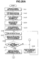
- step S1 a confirmation is made with regard to a position of the origin of the blower unit 5 and that of the origin of the mold clamping unit 3 (step S1).
- a lamp is flickered during a centering of the calibrating unit 5 (step S2).
- the stripper plate 11c and the blow pin 11b of the calibrating unit 5 are started (step S3), and moved downward at low speed (step S4).
- the blow pin 11b and the stripper plate 11c are stopped in a detected position (step S5), i.e., in a state as shown in Fig. 19.
- Detection air is blown from the blowout openings 405A-405D (step S6).
- the fluid supply source 409 sends air to the passages 407 so as to blow it from the blowout openings 405A-405D. Air is blown against the conical outer peripheral face 501 of the stripper bush 516, and discharged outside from a clearance between the stripper bush 516 and the conical inner peripheral face 432 of the cutting plate 431.
- the stripper bush 516 i.e., the blow pin 11b
- the back pressures or flow rates of air blown from the blowout openings 405A-405D are different from each other.
- the back pressure or flow rate may be measured by blowing air against the outer peripheral face of the blow pin 11b in place of the stripper bush 516.
- the pressures or flow rates of air are detected by pressure sensors 408A-408D or flow sensors, which are input to the control unit 618 so as to calculate the difference of detection values.
- the servo motors 619, 620 are operated so that the difference of the detection values is zero, swinging the blow pin 11b in the X-axis or Y-axis direction.
- the blow pin 11b can be positioned in the center of the conical inner peripheral face 432 of the cutting plate 431.
- characteristics of the pressure sensors 408A-408D are previously stored in the control unit 618.
- the control unit 618 reads detection values of the pressure sensors 408A, 408C to operate the servo motors 619, 620 in the X-axis and Y-axis directions by the difference between the two (step S7), and detection values of the pressure sensors 408B, 408D to operate the servo motors 619, 620 in the X-axis and Y-axis directions by the difference between the two (step S8).
- the calibrating unit 5 is moved further downward for confirmation (step S9), and it is determined whether or not the detection values of the pressure sensors 408A-408D are within a predetermined allowable limit (step S10).
- step S10 If the answer at the step S10 is YES, a centering of the calibrating unit 5 is completed, and the lamp is turned on (step S11). Then, the stripper plate 431 is moved upward (step S12), and the blow pin 11b is moved upward or to the origin (step S13), finishing all centering operation of the calibrating unit 5.
- step S10 If the answer at the step S10 is NO, the flow is returned to the step S7.
- blow pin 11b is positioned in the center of the conical inner peripheral face 432 of the cutting plate 431, no deformation of the shape of a product opening, nor imperfection in a screw thread to be formed on an outer peripheral face of the product opening is produced.
- FIGs. 25-26B another example of an automatic centering equipment will be described.
- the constitution of this example is substantially the same as the example as described in connection with Figs. 19 to 21.
- the rails 6 are mounted on the base 1, and the support 7 is slidably disposed on the rails 6.
- the support 7 is formed with the vertical wall 7a having a front face on which the rails 8 are mounted in the direction perpendicular to the rails 6.
- the arm 9 is horizontally movably supported on the rails 8 so as to fix the calibrating unit 5.
- the calibrating unit 5 is movable in the longitudinal direction of the base 1 as viewed in Fig. 4 along the rails 6 by rotation of the servo motor 5d, and in the cross direction of the base 1 as viewed in Fig. 4 along the rails 8 by rotation of the servo motor 5c.
- step S101 a position of the origin of the mold clamping unit 3 is confirmed (step S101), then a position of the origin of the calibrating unit 5 is confirmed (step S102).
- step S103 The stripper plate 11c and the blow pin 11b of the calibrating unit 5 are started (step S103), and moved downward at low speed (step S104).
- step S105 The blow pin 11b and the stripper plate 11c are stopped in a detected position (step S105), i.e., in a state as shown in Fig. 19.
- Detection air is blown from the blowout openings 405A-405D (step S106). Specifically, when the stripper bush 516 is inserted into the cutting plate 431, the fluid supply source 409 sends air to the passages 407 so as to blow it from the blowout openings 405A-405D. Air is blown against the conical outer peripheral face 501 of the stripper bush 516, and discharged outside from a clearance between the stripper bush 516 and the conical inner peripheral face 432 of the cutting plate 431.
- the stripper bush 516 i.e., the blow pin 11b
- the back pressures or flow rates of air blown from the blowout openings 405A-405D are different from each other.
- the back pressure or flow rate may be measured by blowing air against the outer peripheral face of the blow pin 11b in place of the stripper bush 516.
- a solenoid valve 403A as shown in Fig. 25 is turned on to blow air from the blowout opening 405A, and after a predetermined period of time, e.g., "t" sec., the control unit 618 reads a value of the pressure sensor 408. Then, with the solenoid valve 403A turned off, and the solenoid valve 403B turned on to blow air from the blowout opening 405B, the control unit 618 reads a value of the pressure sensor 408.
- a similar operation is carried out in sequence for the solenoid valves 403C, 403D to read values of the pressure sensor 405 (step S107). It is to be noted that the pressure is low when a clearance between the cutting plate 431 and the stripper bush 516 is large, whereas the pressure is high when the clearance is small.
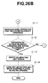
- step S108 it is checked whether or not one of the values of the pressure sensor 408 is over a predetermined lower limit. If the answer at the step S108 is NO, the calibrating unit 5 is moved downward by a predetermined distance, e.g., "n" mm (step S109), and the flow is returned to the step S106. On the other hand, if the answer at the step S108 is YES, the servo motors 5c, 5d are driven at the same revolution so that the blow pin 11b is moved at low speed in the direction opposite to a reference position which corresponds to one of the blowout openings 405A-405D having the maximum pressure.
- a predetermined distance e.g., "n" mm
- step S110 the solenoid valve corresponding to another blowout opening opposite to the reference position is kept turned on.
- the servo motors 5c, 5d are stopped.
- the servo motors 5c, 5d are backed by 1/2 the distance between start and stop positions thereof (step S110).
- a similar operation is carried out for the two other blowout openings, obtaining X-axis and Y-axis center of the blow pin 11b (step S111). Subsequently, it is determined whether or not the pressure difference in four blowout openings 405A-405D is within a predetermined allowable limit (step S112). It is to be understood that until all the pressures of the blowout openings 405A-405D are over the lower limit and the pressure difference in four blowout openings 405A-405D is within a predetermined allowable limit, a similar detection or measurement is carried out by moving the calibrating unit 5 downward by "n" mm per detection.
- step S113 When confirming that all the pressures of the blowout openings 405A-405D are over the lower limit and the pressure difference in four blowout openings 405A-405D is within the predetermined allowable limit, the origin of the calibrating unit 5 is written (step S113). Detection air is turned off, and the stripper plate 11c and the blow pin 11b are moved upward or to the origin (step S114), finishing all centering operation of the calibrating unit 5.
- blow pin 11b is positioned in the center of the conical inner peripheral face 432 of the cutting plate 431, no deformation of the shape of a product opening, nor imperfection in a screw thread to be formed on an outer peripheral face of the product opening is produced.
Landscapes
- Engineering & Computer Science (AREA)
- Mechanical Engineering (AREA)
- Manufacturing & Machinery (AREA)
- Robotics (AREA)
- Blow-Moulding Or Thermoforming Of Plastics Or The Like (AREA)
Claims (13)
- Procédé pour commander une machine de moulage par soufflage à partir de la fin de fabrication d'un produit en résine au commencement de fabrication d'un produit suivant, la machine de moulage par soufflage comportant une pluralité de dispositifs,le procédé comprend les étapes consistant à :commander une température de la résine à l'intérieur de la machine de moulage par soufflage ;commander un fonctionnement de la pluralité de dispositifs depuis la fin de la production d'un produit en résine au début de la production du produit suivant ;où ledit fonctionnement de la pluralité de dispositifs comporte le détachement d'un axe de soufflage (11) d'une unité de calibrage (5) et le montage d'un bâti de transport (43) sur ladite unité de calibrage (5) et l'échange de quelques-uns de la pluralité des dispositifs en utilisant le bâti de transport (43) monté sur l'unité de calibrage (5);commander un transport suivant de quelques-uns de la pluralité de dispositifs dans des positions prédéterminées et commander un changement de la résine en accord avec un arrêt d'amenée de la résine et d'une donnée se rapportant au produit suivant.
- Procédé pour commander une machine de moulage par soufflage selon la revendication 1, ou quelques-uns de la pluralité de dispositifs comprennent ledit moule (4), matrice (2a), noyau (2b) et axe de soufflage (11), et l'autre moule (71), la matrice, le noyau, l'axe de soufflage (77) pour le produit suivant.
- Procédé pour commander une machine de moulage par soufflage selon la revendication 1 ou 2, où ledit transport suivant de quelques-uns de la pluralité des dispositifs est effectue par ledit bâti de transport (43).
- Procédé pour commander une machine de moulage par soufflage selon l'une des revendications 1 à 3, où ledit fonctionnement de la pluralité de dispositifs comporte en outre un arrêt d'une extrudeuse (2) après avoir pressé la résine dans celle-ci vers l'extérieur, un drainage d'un moule (4), un détachement dudit moule (4) par ledit bâti de transport (43), un détachement d'une matrice (2a) et du noyau (2b), un montage de l'autre matrice et novau avec le produit suivant, un montage de l'autre moule (71) pour le produit suivant, un détachement dudit bâti de transport (43), un montage de l'autre axe de soufflage (77) pour le produit suivant, un centrage de l'autre axe de soufflage (77) et un retour de l'unité de calibrage (5) à l'état initial.
- Procédé pour commander une machine de moulage par soufflage selon l'une des revendications 1 à 4, ou ledit détachement dudit axe de soufflage (11) est effectué par un premier bloc (10), un deuxième bloc (11a) en prise de coulissement avec ledit premier bloc (10) et ayant ledit axe de soufflage (11), et des passages (523, 524) pour fournir des fluides audit axe de soufflage (11), lesdits passages (523, 524) permettant une communication de fluide entre ledit premier bloc (10) et ledit second bloc (11a) dans une position stationnaire des deux, tandis que ledit montage de l'autre axe de soufflage (77) pour le produit suivant est effectué par ledit premier bloc (10), ledit second bloc (11a) étant en prise de coulissement avec ledit premier bloc (10) et ayant l'autre axe de soufflage (77) et lesdits passages (523, 524) pour fournir lesdits fluides à l'autre axe de soufflage (77), lesdits passages permettant une communication de fluide entre ledit premier bloc (10) et ledit second bloc (11a) dans ladite position stationnaire des deux.
- Procédé pour commander une machine de moulage par soufflage selon l'une des revendications 1 à 5, où ledit centrage de l'autre axe de soufflage (77) est effectué en mesurant des variables prédéterminées d'un fluide fourni depuis au moins quatre points (405A-405D) qui sont opposés les uns aux autres dans la direction diamétrale de l'autre axe de soufflage (77) lorsque l'autre axe de soufflage (77) est inséré dans l'autre moule (71) pour le prochain produit en comparant lesdites variables prédéterminées les unes avec les autres pour obtenir des différences entre à chaque fois deux desdits au moins quatre points (405A-405D), et en déplaçant l'autre axe de soufflage (77) de telle manière que lesdites différences desdites variables prédéterminées sont zéro.
- Machine de moulage par soufflage comportant des moyens pour commander la machine de moulage par soufflage entre la fin de production d'un produit et un démarrage de production du produit suivant,ledit moyen comprenant des moyens de commande de température (100) commandant une température dans la machine de moulage par soufflage,un moyen de commande de fonctionnement (101) commandant un fonctionnement de plusieurs dispositifs entre la fin de production d'un produit et le démarrage de production du produit suivant, etun moyen de commande d'échange de monture (102) commandant un transport suivant de quelques-uns de la pluralité de dispositifs dans des positions prédéterminées,où ladite pluralité de dispositifs comprend une unité de calibrage (5) avec un dispositif de montage pouvant être mis en prise avec un axe de soufflage (11) pour produire un produit et pouvant être mis en prise avec un bâti de transport (43) pour échanger quelques-uns de la pluralité de dispositifs.
- Machine de moulage par soufflage selon la revendication 7, où ladite machine de moulage par soufflage comprend un équipement de centrage automatique avec un moule (4) ayant une portion supérieure présentant plusieurs ouvertures (405A-405D) qui sont opposées les unes aux autres dans une direction diamétrale, un premier de moyens de passage de fluide pour fournir ledit fluide à ladite pluralité d'ouvertures (405A-405D) de ladite portion supérieure dudit moule (4), un capteur (408) disposé dans ledit moyen de passage (407), ledit capteur (408) servant à détecter des variables prédéterminées dudit fluide fourni par ladite pluralité d'ouvertures (405A-405D), un axe de soufflage (11b) comportant un élément de centrage (501), ledit élément de centrage (501) étant orienté vers ladite portion supérieure (432) dudit moule (4) selon une distance prédéterminée lorsque ledit axe de soufflage (11b) est inséré dans ledit moule (4), une unité de commande (618) reliée audit capteur (408), ladite unité de commande (618) servant à comparer lesdites variables prédéterminées les unes avec les autres pour obtenir des différences à chaque fois entre deux ouvertures opposées de ladite pluralité d'ouvertures, et un actionneur (619, 620) relié à ladite unité de commande (618), ledit actionneur (619, 620) servant à déplacer ledit axe de soufflage (11b) de telle sorte que lesdites différences sont de zéro.
- Machine de moulage par soufflage selon la revendication 7, où ladite unité de calibrage comprend un premier bloc (10), un second bloc (11a) en prise de coulissement avec ledit premier bloc (10), ledit second bloc (11a) comportant plusieurs axes de soufflage (11b), et un moyen de passage pour permettre une communication de fluide entre ladite pluralité d'axes de soufflage, par quoi la hauteur de ladite pluralité d'axes de soufflage est automatiquement ajustée en accord avec un moule (4) par un fluide dans ce moyen de passage.
- Machine de moulage par soufflage selon la revendication 9, où ladite unité de calibrage comporte en outre une plaque de démoulage (11c) disposée d'une manière mobile sur ledit second bloc (11a), ladite plaque de démoulage (11c) étant agencée autour de chacun de ladite pluralité d'axes de soufflage (11b), ladite plaque de démoulage (11c) coopérant avec ledit moule (4) pour exercer une pression sur une bavure de produit.
- Machine de moulage par soufflage selon la revendication 7, où ladite unité de calibrage comprend un premier bloc (10) présentant une rainure en queue d'aronde (10a), ladite rainure en queue d'aronde (10a) étant définie par des blocs de blocage (504, 505) qui sont déplaçables, un deuxième bloc (11a) engagé d'une manière coulissante dans ladite rainure en queue d'aronde (10a) et un troisième bloc (509) relié audit deuxième bloc (11a), ledit troisième bloc (509) comportant plusieurs axes de soufflage (11b).
- Machine de moulage par soufflage selon la revendication 11, où ledit troisième bloc (509) présente plusieurs chambres de cylindre (513) pour recevoir ladite pluralité d'axes de soufflage (11b) auxquels des corps de buse (515) sont reliés, chaque corps de buse ayant une portion supérieure avec un collecteur (521) connecté à un cylindre (518) qui est rempli d'un fluide de telle sorte que chaque corps de buse (550) est déplaçable axialement, ledit troisième bloc (509) présentant des passages (523) qui correspondent audit collecteur (521) et qui ont des ouvertures dans un côté de celui-ci orientées vers ledit deuxième bloc (11a), ledit deuxième bloc présentant un passage (520) qui communique avec ledit cylindre (518), ledit premier bloc (10) présentant des passages (524) ayant des ouvertures qui sont orientées vers lesdites ouvertures desdits passages (523) dudit troisième bloc (509).
- Machine de moulage par soufflage selon la revendication 12, où ledit cylindre (518) est supporté sur ledit troisième bloc, ledit troisième bloc ayant des tiges de piston (511) reliées à une plaque de démoulage (11c), ladite pluralité d'axes de soufflage (11b) étant agencée à travers ladite plaque de démoulage (11c).
Applications Claiming Priority (9)
| Application Number | Priority Date | Filing Date | Title |
|---|---|---|---|
| JP179543/93 | 1993-07-21 | ||
| JP17954393A JP2865981B2 (ja) | 1993-07-21 | 1993-07-21 | 中空成形機における打込ノズルの交換、高さ調節及びバリ押え方法並びに打込装置 |
| JP17954393 | 1993-07-21 | ||
| JP5215546A JP2865983B2 (ja) | 1993-08-31 | 1993-08-31 | 中空成形機の打込自動心出方法及びその装置 |
| JP215546/93 | 1993-08-31 | ||
| JP21554693 | 1993-08-31 | ||
| JP6065794 | 1994-03-30 | ||
| JP60657/94 | 1994-03-30 | ||
| JP06065794A JP3404426B2 (ja) | 1994-03-30 | 1994-03-30 | 中空成形機における自動運転制御方法 |
Publications (3)
| Publication Number | Publication Date |
|---|---|
| EP0635352A2 EP0635352A2 (fr) | 1995-01-25 |
| EP0635352A3 EP0635352A3 (fr) | 1995-05-24 |
| EP0635352B1 true EP0635352B1 (fr) | 1999-09-29 |
Family
ID=27297255
Family Applications (1)
| Application Number | Title | Priority Date | Filing Date |
|---|---|---|---|
| EP94110823A Expired - Lifetime EP0635352B1 (fr) | 1993-07-21 | 1994-07-12 | Machine de moulage par soufflage |
Country Status (4)
| Country | Link |
|---|---|
| US (3) | US5656214A (fr) |
| EP (1) | EP0635352B1 (fr) |
| CA (1) | CA2127830C (fr) |
| DE (1) | DE69420909T2 (fr) |
Families Citing this family (6)
| Publication number | Priority date | Publication date | Assignee | Title |
|---|---|---|---|---|
| US5516274B1 (en) * | 1994-09-23 | 1997-03-18 | Electra Form Inc | Stretch blow molding machine with movable blow mold assembly |
| ATE314189T1 (de) * | 2000-02-22 | 2006-01-15 | Soplar Sa | Vorrichtung und verfahren zur herstellung von hohlkörpern aus kunststoff |
| US7335007B2 (en) | 2005-04-18 | 2008-02-26 | Graham Packaging Company, L.P. | Quick change mold |
| US7819649B2 (en) * | 2008-03-22 | 2010-10-26 | Milacron Llc | Apparatus for blow molding |
| US8512030B2 (en) * | 2009-03-18 | 2013-08-20 | Antonio Gumercindo Pavan | Blow-molding machine for thermoplastic pieces and containers |
| CN105737870B (zh) * | 2016-04-15 | 2018-05-04 | 洛阳功航机械科技有限公司 | 一种跨河道水文检测装置 |
Family Cites Families (22)
| Publication number | Priority date | Publication date | Assignee | Title |
|---|---|---|---|---|
| BE722491A (fr) * | 1968-10-18 | 1969-04-18 | ||
| US3767341A (en) * | 1971-04-08 | 1973-10-23 | Rheinmetall Gmbh | Blow moulding machine |
| US3860375A (en) * | 1972-03-08 | 1975-01-14 | Ethyl Dev Corp | Blow molding apparatus |
| GB1466855A (en) * | 1974-07-10 | 1977-03-09 | Lucas Batteries Ltd | Apparatus for use in injection moulding or die casting |
| US4832592A (en) * | 1976-07-23 | 1989-05-23 | Saumsiegle Robert W | Hollow article forming apparatus |
| US4187070A (en) * | 1978-03-20 | 1980-02-05 | Roman Machine Co. | Blow molding machine |
| US4197070A (en) * | 1978-08-03 | 1980-04-08 | Owens-Illinois, Inc. | Apparatus for controlling a plastic extruder |
| US4173447A (en) * | 1978-09-05 | 1979-11-06 | Ethyl Development Corporation | Apparatus for contact cooling the neck moil of blown hollow containers |
| US4578028A (en) * | 1984-12-06 | 1986-03-25 | The Procter & Gamble Company | Expandable core pin for blow-molding a container having a neck-portion with internal attachment means |
| JPS61154912A (ja) * | 1984-12-28 | 1986-07-14 | Toyoda Gosei Co Ltd | 金型交換機構を備えた成形装置 |
| DE3613543C1 (de) * | 1986-04-22 | 1986-12-18 | Fried. Krupp Gmbh, 4300 Essen | Schnellspanneinheit für eine Blasform |
| DE3623099C3 (de) * | 1986-07-09 | 1998-08-13 | Spoetzl Markus Dipl Ing Fh | Blasformmaschine |
| DE3636566A1 (de) * | 1986-10-28 | 1988-05-05 | Krupp Gmbh | Spannvorrichtung fuer blasdorne von blasformmaschinen |
| US4880792A (en) * | 1986-11-06 | 1989-11-14 | Mazda Motor Corporation | Molding installation using die |
| US5213726A (en) * | 1987-10-14 | 1993-05-25 | Matrix Technologies, Inc. | Molding and gauging method |
| DE9017716U1 (fr) * | 1990-09-29 | 1991-11-28 | Mauser-Werke Gmbh, 5040 Bruehl, De | |
| US5171584A (en) * | 1991-05-07 | 1992-12-15 | Matrix Technologies, Inc. | System for determining the distance between two solid bodies |
| JP2545088Y2 (ja) * | 1991-10-25 | 1997-08-25 | 株式会社クラタ | ブロー成形機用部品交換装置 |
| EP0549823B1 (fr) * | 1991-12-28 | 1997-04-16 | Kurata Corporation | Dispositif de changement des moules pour appareils de moulage par soufflage |
| US5244610A (en) * | 1992-02-14 | 1993-09-14 | Plastipak Packaging, Inc. | Rotary plastic blow molding |
| DE4208921C1 (fr) * | 1992-03-19 | 1993-04-15 | Rainer 3530 Warburg De Fischer | |
| US5551861A (en) * | 1992-07-31 | 1996-09-03 | Hoover Universal, Inc. | Quick change mold for blow molding apparatus |
-
1994
- 1994-07-12 CA CA002127830A patent/CA2127830C/fr not_active Expired - Lifetime
- 1994-07-12 US US08/274,014 patent/US5656214A/en not_active Expired - Fee Related
- 1994-07-12 EP EP94110823A patent/EP0635352B1/fr not_active Expired - Lifetime
- 1994-07-12 DE DE69420909T patent/DE69420909T2/de not_active Expired - Lifetime
-
1997
- 1997-03-17 US US08/819,373 patent/US5849342A/en not_active Expired - Lifetime
- 1997-11-03 US US08/963,190 patent/US5814354A/en not_active Expired - Lifetime
Also Published As
| Publication number | Publication date |
|---|---|
| DE69420909T2 (de) | 2000-03-09 |
| EP0635352A2 (fr) | 1995-01-25 |
| US5656214A (en) | 1997-08-12 |
| DE69420909D1 (de) | 1999-11-04 |
| US5849342A (en) | 1998-12-15 |
| CA2127830A1 (fr) | 1995-01-22 |
| US5814354A (en) | 1998-09-29 |
| CA2127830C (fr) | 1998-08-11 |
| EP0635352A3 (fr) | 1995-05-24 |
Similar Documents
| Publication | Publication Date | Title |
|---|---|---|
| EP0544902B1 (fr) | Machine a moulage a injection du type a echange de moule automatique | |
| US4063867A (en) | Injection and blowing machine for manufacturing hollow bodies of plastics material | |
| EP0703058B1 (fr) | Dispositif de moulage par soufflage avec deux moules servant respectivement au préformage et au formage final de récipients de grands volumes par un dispositif de fermeture | |
| JP7198913B2 (ja) | シェイパーモジュールによるプラスチック成形装置および方法 | |
| EP0635352B1 (fr) | Machine de moulage par soufflage | |
| US5741528A (en) | Tire vulcanizing system | |
| KR102353811B1 (ko) | 공작물을 이송하기 위한 운반 방법 | |
| EP0817717B1 (fr) | Machine de moulage par injection-soufflage | |
| US3910747A (en) | Apparatus having improved sheet clamping means for forming plastic sheets | |
| CN114455807B (zh) | 多滴料重自动控制的制瓶装备及料重控制方法 | |
| CN116198164A (zh) | 一种轮胎生产用一模多腔平板硫化机 | |
| US5351744A (en) | Device in a press casting machine and method of using such device | |
| US4544519A (en) | Machine and method for producing footwear | |
| CA1096121A (fr) | Methode de moulage par injection de divers articles selon une sequence ordonnee d'avance | |
| JP3404426B2 (ja) | 中空成形機における自動運転制御方法 | |
| JPH0741638B2 (ja) | 射出成形機 | |
| JP3468815B2 (ja) | 中空成形機の打込高さの自動調節方法及びその装置 | |
| JPH11199242A (ja) | I.s.機械用の金型開閉機構 | |
| JP2837835B2 (ja) | 射出成形機における金型要素自動交換方法 | |
| JP3459110B2 (ja) | 中空成形機における金型及び成形用治具の自動交換方法及びその装置 | |
| CN114206580A (zh) | 注射成型系统、输送装置和模具更换方法 | |
| CN115026983B (zh) | 一种滚塑机 | |
| JPH11217225A (ja) | I.s.機械 | |
| JPH11199241A (ja) | I.s.機械用のプランジャ機構及びプランジャ基部モジュール並びにi.s.機械 | |
| JP2865981B2 (ja) | 中空成形機における打込ノズルの交換、高さ調節及びバリ押え方法並びに打込装置 |
Legal Events
| Date | Code | Title | Description |
|---|---|---|---|
| PUAI | Public reference made under article 153(3) epc to a published international application that has entered the european phase |
Free format text: ORIGINAL CODE: 0009012 |
|
| 17P | Request for examination filed |
Effective date: 19940712 |
|
| AK | Designated contracting states |
Kind code of ref document: A2 Designated state(s): DE FR IT |
|
| PUAL | Search report despatched |
Free format text: ORIGINAL CODE: 0009013 |
|
| AK | Designated contracting states |
Kind code of ref document: A3 Designated state(s): DE FR IT |
|
| 17Q | First examination report despatched |
Effective date: 19961105 |
|
| GRAG | Despatch of communication of intention to grant |
Free format text: ORIGINAL CODE: EPIDOS AGRA |
|
| GRAG | Despatch of communication of intention to grant |
Free format text: ORIGINAL CODE: EPIDOS AGRA |
|
| GRAH | Despatch of communication of intention to grant a patent |
Free format text: ORIGINAL CODE: EPIDOS IGRA |
|
| GRAH | Despatch of communication of intention to grant a patent |
Free format text: ORIGINAL CODE: EPIDOS IGRA |
|
| GRAA | (expected) grant |
Free format text: ORIGINAL CODE: 0009210 |
|
| AK | Designated contracting states |
Kind code of ref document: B1 Designated state(s): DE FR IT |
|
| REF | Corresponds to: |
Ref document number: 69420909 Country of ref document: DE Date of ref document: 19991104 |
|
| ITF | It: translation for a ep patent filed |
Owner name: SOCIETA' ITALIANA BREVETTI S.P.A. |
|
| ET | Fr: translation filed | ||
| PLBE | No opposition filed within time limit |
Free format text: ORIGINAL CODE: 0009261 |
|
| STAA | Information on the status of an ep patent application or granted ep patent |
Free format text: STATUS: NO OPPOSITION FILED WITHIN TIME LIMIT |
|
| 26N | No opposition filed | ||
| PGFP | Annual fee paid to national office [announced via postgrant information from national office to epo] |
Ref country code: DE Payment date: 20130722 Year of fee payment: 20 |
|
| PGFP | Annual fee paid to national office [announced via postgrant information from national office to epo] |
Ref country code: FR Payment date: 20130722 Year of fee payment: 20 |
|
| PGFP | Annual fee paid to national office [announced via postgrant information from national office to epo] |
Ref country code: IT Payment date: 20130726 Year of fee payment: 20 |
|
| REG | Reference to a national code |
Ref country code: DE Ref legal event code: R071 Ref document number: 69420909 Country of ref document: DE |
|
| PG25 | Lapsed in a contracting state [announced via postgrant information from national office to epo] |
Ref country code: DE Free format text: LAPSE BECAUSE OF EXPIRATION OF PROTECTION Effective date: 20140715 |