EP0633601A2 - Détecteur pour spectromètre de masse à temps de vol présentant des distorsions réduites des temps de vols à ouverture élevée - Google Patents
Détecteur pour spectromètre de masse à temps de vol présentant des distorsions réduites des temps de vols à ouverture élevée Download PDFInfo
- Publication number
- EP0633601A2 EP0633601A2 EP94110272A EP94110272A EP0633601A2 EP 0633601 A2 EP0633601 A2 EP 0633601A2 EP 94110272 A EP94110272 A EP 94110272A EP 94110272 A EP94110272 A EP 94110272A EP 0633601 A2 EP0633601 A2 EP 0633601A2
- Authority
- EP
- European Patent Office
- Prior art keywords
- ion
- conversion surface
- time
- detector
- electron conversion
- Prior art date
- Legal status (The legal status is an assumption and is not a legal conclusion. Google has not performed a legal analysis and makes no representation as to the accuracy of the status listed.)
- Granted
Links
Images
Classifications
-
- H—ELECTRICITY
- H01—ELECTRIC ELEMENTS
- H01J—ELECTRIC DISCHARGE TUBES OR DISCHARGE LAMPS
- H01J49/00—Particle spectrometers or separator tubes
- H01J49/02—Details
- H01J49/06—Electron- or ion-optical arrangements
-
- H—ELECTRICITY
- H01—ELECTRIC ELEMENTS
- H01J—ELECTRIC DISCHARGE TUBES OR DISCHARGE LAMPS
- H01J49/00—Particle spectrometers or separator tubes
- H01J49/26—Mass spectrometers or separator tubes
- H01J49/34—Dynamic spectrometers
- H01J49/40—Time-of-flight spectrometers
Definitions
- the invention relates to detectors for time-of-flight mass spectrometers according to the preambles of claims 1 and 3, respectively.
- Detectors for time-of-flight mass spectrometers should oppose the incident ion beam to as large an area as possible and still have small time-of-flight errors.
- Each detector has an ion-electron conversion surface on which, at the time of the impact of an ion, one or more electrons are generated with a certain probability, which are amplified in one or more downstream electron multipliers. This results in an electrical impulse, which is related in time to the impact of the ion on the conversion surface.
- the ion-optical axis of a detector means a selected path in or near the center of the incident ion beam. If the detector has a cylindrical symmetry, the axis of symmetry is usually chosen.
- the ion-optical axis can be traced backwards from the ion-electron conversion surface out of the detector to a suitably chosen point, and a reference plane can be defined at this point normal to the ion-optical axis.
- the flight time along the ion-optical axis from the reference plane to the ion-electron conversion surface can be selected as the reference flight time. If ions are launched into the detector from points other than the axis point of the reference plane, but with the same direction and speed, they may need different flight times than an ion the axis. The difference between these flight times and the reference flight time on the ion-optical axis is called the flight time error.
- the flight time errors can be specified as a function of the starting location on the reference level. In the most general case, the flight time errors depend on the two variables that parameterize the reference level. If the detector is constructed cylindrically symmetrically, the time-of-flight errors are a function of the distance of the orbit in question from the ion-optical axis in the reference plane.
- Ions can be focused or scattered on a smaller or larger area within a detector with an inhomogeneous electric field. For this reason, the usable area on the ion-electron conversion surface is not suitable as a measure of the sensitivity of the detector.
- the content of the area on the reference plane from which ions with acceptably small time-of-flight errors can be launched into the detector offers itself.
- time-of-flight errors By defining a reference plane and only looking at the orbits from the reference plane to the conversion surface, one can mentally separate the detector and its time-of-flight errors from the rest of the time-of-flight mass spectrometer. However, it is also possible to determine the flight time errors over the entire flight route from the ion source to the conversion area. In addition to the time-of-flight errors directly related to the detector structure, time-of-flight errors often occur on the path through the ion source and reflector, which can be compensated in part by tilting the ion-electron conversion surface. For this reason, the conversion surface is often movably mounted.
- the probability that electrons are released when an ion impacts the ion-electron conversion surface, i.e. the electron yield depends very much on the speed of the impact. Since the velocity of the ions is inversely proportional to the square root of their mass, the probability of detection with ions of large mass is greatly reduced.
- a detector If a detector is to detect ions of greater mass, the ions must therefore be post-accelerated before they strike the ion-electron conversion surface in order to release electrons from the conversion surface with a sufficient probability when they strike.
- the detector must therefore be constructed in such a way that a strong, accelerating electric field is present in front of the conversion surface. Flight time errors can arise from this post-acceleration field.
- a homogeneous field has a location-independent direction and strength of the electric field, which means that in a detector with homogeneous fields, the flight time from the reference plane to the ion-electron conversion surface is independent of the starting point on the reference plane or independent of the entry point into the post-acceleration field.
- Such an electric field can only be generated if the post-acceleration field is delimited from the drift path of the time-of-flight mass spectrometer with a grating.
- An example of such a detector is shown in Fig. 5 of de Heer et al. (Review of Scientific Instruments, Volume 62 (3), page 670-677, 1991).
- the size of the flight time errors is a function of the distance of the flight path from the ion optical axis.
- the distance to the ion-optical axis on the reference plane, not on the conversion surface, should be taken as a variable in this function.
- the size of these time-of-flight errors is proportional to the square of the distance from the ion-optical axis.
- the detector in order to keep the time-of-flight errors small, the detector should only be charged with ions close to the ion-optical axis. This means that ions from the reference plane can only be launched into the detector near the ion-optical axis. It does not matter whether the ion trajectories are focused or defocused on a smaller or larger area within the detector.
- the measure of the sensitivity of the detector is the content of that area on the reference plane from which ion trajectories with acceptably small flight time errors can be started into the detector.
- the invention is accordingly based on the object of specifying a detector for time-of-flight mass spectrometers which equally ensures high sensitivity and high mass resolution.
- the time-of-flight errors between ions with different trajectories generated by the inhomogeneous electric field prevailing in the detector or occurring before the detector are compensated by the detector itself. This is done by using a curved ion-electron conversion surface in the detector.
- the curvature causes the flight time occurring in each flight path to vary depending on the lateral position on the ion beam, i.e. is either lengthened or shortened so that the flight time errors caused by the inhomogeneous field or occurring in front of the detector are compensated for or at least minimized.
- the shape of the conversion surface is also possible to specify the shape of the conversion surface as a power series of finite order. This would mean that one does not adopt the exact shape of the area determined in step 5, but optimally approximates this area with a power series, and then continues with this area in step 3.
- lanes can also be used which are started from the ion source with initial conditions corresponding to the actual operation of the time-of-flight mass spectrometer.
- time-of-flight errors such as those which arise in the ion source and in the other parts of the time-of-flight mass spectrometer can also be included in the determination of the curvature of the ion-electron conversion surface.
- the space of the initial conditions in this case has 6 coordinates, that is, 3 for initial speeds and 3 for initial coordinates. Since the end face is a 2-parameter area in 3-dimensional space, the end face (20) must be adapted to the end points of the tracks (11) in such a way that the average distance between the track end points and the end face (20) is minimal.
- the method can also be designed in such a way that first a design of the detector electrodes including a specific curvature of the ion-electron conversion surface is determined, and then the voltages are varied until the flight time errors fall below a predetermined limit. This procedure corresponds to procedural claim 10.
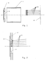
- 3 shows the simplest embodiment of a detector according to the invention.
- the time-of-flight errors of off-axis paths are compensated for by a curved conversion surface (3).
- the only ring electrode (1) is at the potential of the drift path.
- this embodiment also corresponds to claim 7.
- tilting a movably mounted holder it is possible to detect certain time-of-flight errors of the ion source, the reflector and / or the drift path of the time-of-flight mass spectrometer in the detector to compensate.
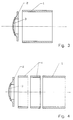
- Fig. 4 shows a detector design in which the field of the post-acceleration path can be adjusted by additional ring electrodes (4). In this way, the necessary curvature of the conversion surface (3) can be kept smaller at a certain voltage than in the design of FIG. 3 . Alternatively, a higher post-acceleration voltage can be set with the same curvature of the ion-electron conversion surface (3).
- the additional ring electrodes (4) reduce the time-of-flight errors of off-axis orbits by placing the areas of greater field curvature in areas in which the speed of the ions is already greater.
- the ring electrodes are placed on potentials whose values lie between the drift path potential and the potential of the ion-electron conversion surface (3). Instead of two or more ring electrodes (4), a single additional ring electrode would also be conceivable.
- the flight time errors of off-axis orbits become greater.
- the ion orbits also bent more towards the ion-optical axis. Both require that the curvature of the ion-electron conversion surface has to increase with greater post-acceleration potential. If the ion trajectories are bent so strongly towards the ion-optical axis that they all hit one point on the conversion surface, it is no longer possible to compensate for the flight time errors by curvature of the conversion surface. This is only possible with even higher post-acceleration potentials if the ion trajectories cross in front of the conversion surface.
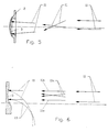
- a detector is to be operated with a large post-acceleration potential, it is advantageous, as shown in FIG. 5 , to operate it according to method claim 8.
- arbitrarily high post-acceleration voltages can be achieved with a comparatively small curvature of the ion-electron conversion surface (3) by ensuring that the ion paths (11) cross in front of the conversion surface by means of a suitable arrangement of the electrodes and suitable setting of the voltages. Since a number of possibilities are known for arranging electrodes or adjusting voltages in such a way that an electric field with the required properties results, the electrodes are not shown here.
- FIG. 6 shows a detector design according to claim 6, in which the electrons generated on the curved ion-electron conversion surface (3) are withdrawn transversely to the detector axis by a field superimposed on the post-acceleration field.
- the electron tracks (15) are shown in dashed lines.
- the ion trajectories (11) are shown twice in the middle part of the post-acceleration section, since here, similar to Fig. 5 , it is possible to cause crossing (11a) ion trajectories, or the ion trajectories essentially parallel (11b) to the ion Electron conversion surface (3) to lead.
- the optimal curvature of the conversion surface may no longer be rotationally symmetrical.
- the detection of the generated electrons can be done using a multi-channel plate, scintillator or similar. be effected.
Landscapes
- Chemical & Material Sciences (AREA)
- Analytical Chemistry (AREA)
- Other Investigation Or Analysis Of Materials By Electrical Means (AREA)
- Electron Tubes For Measurement (AREA)
Applications Claiming Priority (2)
| Application Number | Priority Date | Filing Date | Title |
|---|---|---|---|
| DE4322104A DE4322104A1 (de) | 1993-07-02 | 1993-07-02 | Detektor für Flugzeit-Massenspektrometer mit geringen Flugzeitfehlern bei gleichzeitig großer Öffnung |
| DE4322104 | 1993-07-02 |
Publications (3)
| Publication Number | Publication Date |
|---|---|
| EP0633601A2 true EP0633601A2 (fr) | 1995-01-11 |
| EP0633601A3 EP0633601A3 (fr) | 1995-11-22 |
| EP0633601B1 EP0633601B1 (fr) | 1998-10-14 |
Family
ID=6491838
Family Applications (1)
| Application Number | Title | Priority Date | Filing Date |
|---|---|---|---|
| EP94110272A Expired - Lifetime EP0633601B1 (fr) | 1993-07-02 | 1994-07-01 | Détecteur pour spectromètre de masse à temps de vol présentant des distorsions réduites des temps de vols à ouverture élevée |
Country Status (7)
| Country | Link |
|---|---|
| US (1) | US5637869A (fr) |
| EP (1) | EP0633601B1 (fr) |
| JP (1) | JPH0831372A (fr) |
| AT (1) | ATE172323T1 (fr) |
| AU (1) | AU685114B2 (fr) |
| CA (1) | CA2127184A1 (fr) |
| DE (2) | DE4322104A1 (fr) |
Families Citing this family (8)
| Publication number | Priority date | Publication date | Assignee | Title |
|---|---|---|---|---|
| JPH10188881A (ja) * | 1996-12-26 | 1998-07-21 | Yokogawa Analytical Syst Kk | 飛行時間型質量分析装置及びイオンビーム用収束レンズ |
| US6013913A (en) * | 1998-02-06 | 2000-01-11 | The University Of Northern Iowa | Multi-pass reflectron time-of-flight mass spectrometer |
| US20050099761A1 (en) * | 2001-10-18 | 2005-05-12 | Pst Associates, Llc | Field converter for thrust generation |
| US6891712B2 (en) * | 2001-10-18 | 2005-05-10 | Pst Associates, Llc | Field converter |
| GB2398924C (en) * | 2003-02-13 | 2007-03-13 | Micromass Ltd | Ion detector |
| US7141785B2 (en) | 2003-02-13 | 2006-11-28 | Micromass Uk Limited | Ion detector |
| CN103745908B (zh) * | 2014-01-10 | 2016-06-22 | 清华大学深圳研究生院 | 一种时间补偿离子检测器及弯曲型离子迁移谱仪 |
| US9666423B2 (en) | 2014-05-22 | 2017-05-30 | W Henry Benner | Instruments for measuring ion size distribution and concentration |
Citations (3)
| Publication number | Priority date | Publication date | Assignee | Title |
|---|---|---|---|---|
| DE2534796A1 (de) * | 1975-08-04 | 1977-02-10 | Max Planck Gesellschaft | Ionen-elektronen-konverter |
| SU1274547A2 (ru) * | 1984-08-10 | 1988-04-30 | Институт Аналитического Приборостроения Научно-Технического Объединения Ан Ссср | Устройство дл масс-спектрометрического анализа |
| WO1992019367A1 (fr) * | 1991-04-25 | 1992-11-12 | Applied Biosystems, Inc. | Spectrometre de masse a temps de vol comprenant une ouverture qui permet d'accorder l'efficacite de la transmission et sa resolution |
Family Cites Families (2)
| Publication number | Priority date | Publication date | Assignee | Title |
|---|---|---|---|---|
| US4472631A (en) * | 1982-06-04 | 1984-09-18 | Research Corporation | Combination of time resolution and mass dispersive techniques in mass spectrometry |
| US5160840A (en) * | 1991-10-25 | 1992-11-03 | Vestal Marvin L | Time-of-flight analyzer and method |
-
1993
- 1993-07-02 DE DE4322104A patent/DE4322104A1/de not_active Withdrawn
-
1994
- 1994-06-30 CA CA002127184A patent/CA2127184A1/fr not_active Abandoned
- 1994-07-01 EP EP94110272A patent/EP0633601B1/fr not_active Expired - Lifetime
- 1994-07-01 DE DE59407075T patent/DE59407075D1/de not_active Expired - Fee Related
- 1994-07-01 AU AU66154/94A patent/AU685114B2/en not_active Ceased
- 1994-07-01 AT AT94110272T patent/ATE172323T1/de not_active IP Right Cessation
- 1994-07-01 US US08/269,545 patent/US5637869A/en not_active Expired - Fee Related
- 1994-07-04 JP JP6152490A patent/JPH0831372A/ja active Pending
Patent Citations (3)
| Publication number | Priority date | Publication date | Assignee | Title |
|---|---|---|---|---|
| DE2534796A1 (de) * | 1975-08-04 | 1977-02-10 | Max Planck Gesellschaft | Ionen-elektronen-konverter |
| SU1274547A2 (ru) * | 1984-08-10 | 1988-04-30 | Институт Аналитического Приборостроения Научно-Технического Объединения Ан Ссср | Устройство дл масс-спектрометрического анализа |
| WO1992019367A1 (fr) * | 1991-04-25 | 1992-11-12 | Applied Biosystems, Inc. | Spectrometre de masse a temps de vol comprenant une ouverture qui permet d'accorder l'efficacite de la transmission et sa resolution |
Non-Patent Citations (1)
| Title |
|---|
| DATABASE WPI Section EI, Week 8848 Derwent Publications Ltd., London, GB; Class S03, AN 88-344396 & SU-A-1 274 547 ( AS ANALYT INSTRM IN) , 30.April 1988 * |
Also Published As
| Publication number | Publication date |
|---|---|
| DE59407075D1 (de) | 1998-11-19 |
| EP0633601A3 (fr) | 1995-11-22 |
| AU685114B2 (en) | 1998-01-15 |
| EP0633601B1 (fr) | 1998-10-14 |
| DE4322104A1 (de) | 1995-01-19 |
| AU6615494A (en) | 1995-01-12 |
| JPH0831372A (ja) | 1996-02-02 |
| US5637869A (en) | 1997-06-10 |
| CA2127184A1 (fr) | 1995-01-03 |
| ATE172323T1 (de) | 1998-10-15 |
Similar Documents
| Publication | Publication Date | Title |
|---|---|---|
| DE102018208174B4 (de) | Massenspektrometer und Verfahren für Fluqzeit-Massenspektrometrie | |
| DE69921900T2 (de) | Flugzeitmassenspektrometer und doppelverstärkungsdetektor dafür | |
| DE3920566C2 (fr) | ||
| DE112010005323B4 (de) | Offenes Fallen-Massenspektrometer | |
| DE112007002456B4 (de) | Mehrkanal-Detektion | |
| DE69230174T2 (de) | Flugzeitmassenspektrometer mit einer oeffnung zum ausgleich von uebertragungsvermoegen und aufloesung | |
| EP0208894B1 (fr) | Spectromètre de masses à temps de vol avec Un réflecteur d'ions | |
| DE60319029T2 (de) | Massenspektrometer | |
| DE112011102323B4 (de) | Ionendetektionsanordnung | |
| DE112012004909T5 (de) | lonenspektrometer mit hohem Tastverhältnis | |
| DE102012202993B4 (de) | Ionenschneider mit Beschleunigungs- und Verlangsamungs-Optik | |
| DE1937482A1 (de) | Mikrostrahlsonde | |
| DE10162267B4 (de) | Reflektor für Flugzeitmassenspektrometer mit orthogonalem Ioneneinschuss | |
| DE19635645C2 (de) | Verfahren für die hochauflösende Spektrenaufnahme von Analytionen in einem linearen Flugzeitmassenspektrometer | |
| DE102005023590A1 (de) | ICP-Massenspektrometer | |
| DE102013015046B4 (de) | Bildgebendes Massenspektrometer und Verfahren zum Steuern desselben | |
| EP0633601B1 (fr) | Détecteur pour spectromètre de masse à temps de vol présentant des distorsions réduites des temps de vols à ouverture élevée | |
| DE2540505A1 (de) | Flugzeit-massenspektrometer fuer ionen mit unterschiedlichen energien | |
| DE69121463T2 (de) | Ionenbündelvorrichtung | |
| EP0633602B1 (fr) | Spectromètre de masse à temps de vol pourvu d'une source d'ions en phase gaseuze présentant une sensibilité élevée ainsi qu'une large gamme dynamique | |
| DE102019113776A1 (de) | Korrektur der Neigung der Ionenfront in einem Flugzeit (TOF)-Massenspektrometer | |
| DE1034884B (de) | Vorrichtung zum Trennen von Ionen verschiedenen Ladungs-Masse-Verhaeltnisses | |
| EP0632482B1 (fr) | Source d'ions en phase gazeuse pour spectromètre de masse à temps de vol, présentant une résolution en masse élevée ainsi qu'une large gamme de masses | |
| DE4002849A1 (de) | Verfahren und massenspektrometer zur massenspektroskopischen bzw. massenspektrometrischen untersuchung von teilchen | |
| EP1817788B1 (fr) | Spectrometre de masse a temps de vol |
Legal Events
| Date | Code | Title | Description |
|---|---|---|---|
| PUAI | Public reference made under article 153(3) epc to a published international application that has entered the european phase |
Free format text: ORIGINAL CODE: 0009012 |
|
| AK | Designated contracting states |
Kind code of ref document: A2 Designated state(s): AT BE CH DE DK FR GB LI NL SE |
|
| PUAL | Search report despatched |
Free format text: ORIGINAL CODE: 0009013 |
|
| AK | Designated contracting states |
Kind code of ref document: A3 Designated state(s): AT BE CH DE DK FR GB LI NL SE |
|
| 17P | Request for examination filed |
Effective date: 19960319 |
|
| GRAG | Despatch of communication of intention to grant |
Free format text: ORIGINAL CODE: EPIDOS AGRA |
|
| 17Q | First examination report despatched |
Effective date: 19970626 |
|
| GRAG | Despatch of communication of intention to grant |
Free format text: ORIGINAL CODE: EPIDOS AGRA |
|
| GRAG | Despatch of communication of intention to grant |
Free format text: ORIGINAL CODE: EPIDOS AGRA |
|
| GRAH | Despatch of communication of intention to grant a patent |
Free format text: ORIGINAL CODE: EPIDOS IGRA |
|
| GRAH | Despatch of communication of intention to grant a patent |
Free format text: ORIGINAL CODE: EPIDOS IGRA |
|
| GRAA | (expected) grant |
Free format text: ORIGINAL CODE: 0009210 |
|
| AK | Designated contracting states |
Kind code of ref document: B1 Designated state(s): AT BE CH DE DK FR GB LI NL SE |
|
| PG25 | Lapsed in a contracting state [announced via postgrant information from national office to epo] |
Ref country code: NL Free format text: LAPSE BECAUSE OF FAILURE TO SUBMIT A TRANSLATION OF THE DESCRIPTION OR TO PAY THE FEE WITHIN THE PRESCRIBED TIME-LIMIT Effective date: 19981014 |
|
| REF | Corresponds to: |
Ref document number: 172323 Country of ref document: AT Date of ref document: 19981015 Kind code of ref document: T |
|
| REG | Reference to a national code |
Ref country code: CH Ref legal event code: EP |
|
| REF | Corresponds to: |
Ref document number: 59407075 Country of ref document: DE Date of ref document: 19981119 |
|
| PG25 | Lapsed in a contracting state [announced via postgrant information from national office to epo] |
Ref country code: SE Free format text: LAPSE BECAUSE OF FAILURE TO SUBMIT A TRANSLATION OF THE DESCRIPTION OR TO PAY THE FEE WITHIN THE PRESCRIBED TIME-LIMIT Effective date: 19990114 Ref country code: DK Free format text: LAPSE BECAUSE OF FAILURE TO SUBMIT A TRANSLATION OF THE DESCRIPTION OR TO PAY THE FEE WITHIN THE PRESCRIBED TIME-LIMIT Effective date: 19990114 |
|
| GBT | Gb: translation of ep patent filed (gb section 77(6)(a)/1977) |
Effective date: 19990104 |
|
| ET | Fr: translation filed | ||
| REG | Reference to a national code |
Ref country code: CH Ref legal event code: NV Representative=s name: RITSCHER & SEIFERT |
|
| NLV1 | Nl: lapsed or annulled due to failure to fulfill the requirements of art. 29p and 29m of the patents act | ||
| PG25 | Lapsed in a contracting state [announced via postgrant information from national office to epo] |
Ref country code: BE Free format text: LAPSE BECAUSE OF NON-PAYMENT OF DUE FEES Effective date: 19990731 |
|
| PLBE | No opposition filed within time limit |
Free format text: ORIGINAL CODE: 0009261 |
|
| STAA | Information on the status of an ep patent application or granted ep patent |
Free format text: STATUS: NO OPPOSITION FILED WITHIN TIME LIMIT |
|
| 26N | No opposition filed | ||
| BERE | Be: lapsed |
Owner name: BERGMANN THORALD Effective date: 19990731 Owner name: BERGMANN EVA MARTINA Effective date: 19990731 |
|
| PGFP | Annual fee paid to national office [announced via postgrant information from national office to epo] |
Ref country code: AT Payment date: 20000714 Year of fee payment: 7 |
|
| PG25 | Lapsed in a contracting state [announced via postgrant information from national office to epo] |
Ref country code: AT Free format text: LAPSE BECAUSE OF NON-PAYMENT OF DUE FEES Effective date: 20010701 |
|
| PGFP | Annual fee paid to national office [announced via postgrant information from national office to epo] |
Ref country code: CH Payment date: 20010726 Year of fee payment: 8 |
|
| REG | Reference to a national code |
Ref country code: GB Ref legal event code: IF02 |
|
| PGFP | Annual fee paid to national office [announced via postgrant information from national office to epo] |
Ref country code: GB Payment date: 20020703 Year of fee payment: 9 |
|
| PGFP | Annual fee paid to national office [announced via postgrant information from national office to epo] |
Ref country code: FR Payment date: 20020730 Year of fee payment: 9 |
|
| PG25 | Lapsed in a contracting state [announced via postgrant information from national office to epo] |
Ref country code: LI Free format text: LAPSE BECAUSE OF NON-PAYMENT OF DUE FEES Effective date: 20020731 Ref country code: CH Free format text: LAPSE BECAUSE OF NON-PAYMENT OF DUE FEES Effective date: 20020731 |
|
| PGFP | Annual fee paid to national office [announced via postgrant information from national office to epo] |
Ref country code: DE Payment date: 20020731 Year of fee payment: 9 |
|
| REG | Reference to a national code |
Ref country code: CH Ref legal event code: PL |
|
| PG25 | Lapsed in a contracting state [announced via postgrant information from national office to epo] |
Ref country code: GB Free format text: LAPSE BECAUSE OF NON-PAYMENT OF DUE FEES Effective date: 20030701 |
|
| PG25 | Lapsed in a contracting state [announced via postgrant information from national office to epo] |
Ref country code: DE Free format text: LAPSE BECAUSE OF NON-PAYMENT OF DUE FEES Effective date: 20040203 |
|
| GBPC | Gb: european patent ceased through non-payment of renewal fee |
Effective date: 20030701 |
|
| PG25 | Lapsed in a contracting state [announced via postgrant information from national office to epo] |
Ref country code: FR Free format text: LAPSE BECAUSE OF NON-PAYMENT OF DUE FEES Effective date: 20040331 |
|
| REG | Reference to a national code |
Ref country code: FR Ref legal event code: ST |