EP0631973B1 - Flaschenzug mit Handantrieb - Google Patents
Flaschenzug mit Handantrieb Download PDFInfo
- Publication number
- EP0631973B1 EP0631973B1 EP94304888A EP94304888A EP0631973B1 EP 0631973 B1 EP0631973 B1 EP 0631973B1 EP 94304888 A EP94304888 A EP 94304888A EP 94304888 A EP94304888 A EP 94304888A EP 0631973 B1 EP0631973 B1 EP 0631973B1
- Authority
- EP
- European Patent Office
- Prior art keywords
- load
- chain
- sheave
- guide
- anchoring
- Prior art date
- Legal status (The legal status is an assumption and is not a legal conclusion. Google has not performed a legal analysis and makes no representation as to the accuracy of the status listed.)
- Expired - Lifetime
Links
Images


Classifications
-
- B—PERFORMING OPERATIONS; TRANSPORTING
- B66—HOISTING; LIFTING; HAULING
- B66D—CAPSTANS; WINCHES; TACKLES, e.g. PULLEY BLOCKS; HOISTS
- B66D3/00—Portable or mobile lifting or hauling appliances
- B66D3/04—Pulley blocks or like devices in which force is applied to a rope, cable, or chain which passes over one or more pulleys, e.g. to obtain mechanical advantage
-
- B—PERFORMING OPERATIONS; TRANSPORTING
- B66—HOISTING; LIFTING; HAULING
- B66D—CAPSTANS; WINCHES; TACKLES, e.g. PULLEY BLOCKS; HOISTS
- B66D3/00—Portable or mobile lifting or hauling appliances
- B66D3/12—Chain or like hand-operated tackles with or without power transmission gearing between operating member and lifting rope, chain or cable
- B66D3/16—Chain or like hand-operated tackles with or without power transmission gearing between operating member and lifting rope, chain or cable operated by an endless chain passing over a pulley or a sprocket
Definitions
- the present invention relates to a manual chain block, and more specifically to a manual chain block having a load sheave supported rotatably between a pair of side plates so as to be driven interlockingly by a manual actuating device such as a hand wheel and the like.
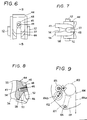
- a manual chain block has a load sheave supported rotatably between a pair of side frames so as to be driven interlockingly by a manual actuating device comprising a hand wheel and a hand chain and a load chain which is looped around the load sheave and has a hook on its load side with its no-load side anchored to an anchoring pin 102 disposed between the side frames 101 as shown in Fig. 9. Further, between the side frames 101 there is provided a load chain guide 105 for making the load chain 104 mesh smoothly with the load sheave 103.
- the load side portion 104a of the load chain 104 is raised or lowered so as to lift or lower a cargo by the hook of its load side end portion.
- the no-load side portion 104b anchored to the anchoring in 102 takes merely a tensioned state so as to be prevented from further unwinding even though the load side portion 104a of the load chain 104 has been unwound for lowering to the utmost limit.
- the anchoring pin 102 is disposed separately aside from the load chain guide 105 with being secured between the side frames 101, not only the number of the component parts increases but also it becomes necessary to carry out such a working as to assemble it to the side frames 101 individually, so that there appears a deficiency also in the assembling workability.
- the anchoring pin 102 is disposed outside the load sheave 103 in the tangential direction, namely at such a position as not to be subjected to the bending stress produced by the load chain guide 105 but to be tensioned linearly. Therefore, a deformation of the no-load side portion 104b can be made less.
- the invention according to claim 1 resides in a manual chain block having a load sheave supported rotatably between a pair of side plates so as to be driven interlockingly by a manual actuating device wherein between said side plates there are provided a pair of load chain guides adapted to guide a load chain coming up to said load sheave, characterised in that the load chain is guided so as to force the chain toward said load sheave and that the no-load side chain guide, serving to guide the no-load side portion of the load chain, has an anchoring portion adapted to anchor the no-load side end portion of said load chain and a load receiving portion adapted to receive a load acting on the no-load side end portion of said load chain and prevent thereby a deformation of the anchoring portion.
- the invention according to claim 2 resides in a manual chain block in which the no-loaded side chain guide is provided with a vertical link receiving portion adapted to receive a vertical link connecting to the no-load side end anchored to the anchoring portion and transferring to the load sheave, and a horizontal link receiving portion adapted to receive a horizontal link.
- each chain guide has a chain deviation restraining portion disposed in such a portion thereof as to face the load sheave on the rear side in the approaching direction of the load chain relative to the load sheave so as to serve to restrain a radially outward deviation of the chain relative to the load sheave on that rear side.
- each chain guide has a guide portion disposed in such a portion thereof as to face the load sheave on the fore side in the approaching direction of the load chain relative to the load sheave so as to correct a twist of the load chain coming up to the load sheave.
- the anchoring portion provided with the load receiving portion is disposed in the no-load side chain guide of the pair of load chain guides even in the case that the no-load side portion of the load chain is excessively tensioned by an unwinding of the load chain beyond the unwinding limit or by a cancellation of a traction working, the no-load side end portion of the load chain is received by the load receiving portion. Therefore, it is possible to prevent a deformation of the anchoring portion effectively so as to improve its durability.
- the anchoring portion is provided in the no-load side chain guide, it is unnecessary to provide an anchoring member such as the anchoring pin aside from the load chain guide differently from the conventional embodiment, so that the number of component parts can be reduced by that portion, the structure can be simplified and the assembling workability can be improved so as to attain a cost decrease. Since the anchoring portion is provided in the no-load side chain guide, it is possible to make the no-load side portion of the load chain hang smoothly when the no-load side portion of the chain is relaxed from the tensioned state by carrying out the unwinding operation. Accordingly, it is possible to resolve the problem that the no-load side portion of the chain clogs beside the load sheave.
- the vertical link receiving portion and the horizontal link receiving portion are provided in the no-load side chain guide so as to be arranged continuously in series from the anchoring portion, it is possible to prevent a deformation of the no-load side portion of the load chain at the time of excessive tensioning thereof. Since the position of the anchoring portion for anchoring the end of the no-load side portion of the load chain can be brought to the side opposed to the chain guide surface of the chain guide, it becomes possible to hang the no-load side portion of the chain more smoothly when the no-load side portion of the chain is made to relax in the case of unwinding the load chain and so on.
- the deviation restraining portion since the chain deviation restraining portion is disposed in each load chain guide, the deviation restraining portion can restrain the load chain being apt to deviate radially outwards from the load sheave due to its gravity at the position where the load chain entered between the side plates passes through the load chain guide in the case of conveyance of the chain block or traction of the load chain under the laid or reversed condition of the side plates. Therefore, the load chain having passed through the load sheave can be kept looped around the load sheave without deviation so as to be pulled out without clogging.
- the load chain is pulled out by operating the manual actuating device, it is possible to prevent the load chain from deviating and interfering with the stay bolt or to prevent the load sheave from being locked by clogging.
- a manual chain block illustrated in Figs. 1 and 2 is a manually lifting and lowering type chain block which has a load sheave 3 rotatably supported between a pair of side plates 1, 2 through bearings 5, 6 so that a load chain 4 is looped therearound.
- a driving shaft 7 is inserted into a shaft bore of the load sheave 1 and is provided at its axial one end with a hand wheel 8 around which a endless hand chain (not illustrated) is looped.
- a transmission mechanism 10 provided with a mechanical brake 9 is provided between the hand wheel 8 and the driving shaft 7 while the driving shaft 7 is provided at its other end with a reduction gear mechanism 11 comprising a plurality of reduction gears so that a driving force can be transmitted to the load sheave 3 through the transmission mechanism 10 and the reduction gear mechanism 11 by an actuating operation of the hand wheel 8 through the hand chain so as to lift or lower a hanging member such as a hook connected to a load side portion of the load chain 4 looped around the load sheave 3.
- the side plates 1, 2 are fixedly secured by three stay bolts 12 in a spaced apart state, and an attachment shaft 14 to which a hook 13 is attached is mounted between upper portions of both side plates 1, 2 on one side in the tangential direction of the load sheave 3.
- a wheel cover 15 for covering the hand wheel 8 is attached to the outside of the side plate 1 while a gear cover 16 for covering the reduction gear mechanism 11 is attached to the outside of the side plate 2. Both these covers 15, 16 are fixedly secured by nuts 17 threadably engaged with the stay bolt 12.
- the wheel cover 15 and the gear cover 16 are provided with radial bearings 18, 19 respectively so that the opposite ends of the driving shaft 7 are supported rotatably separately from the load sheave 3 by the respective covers 15, 16 through the bearings 18, 19. A predetermined clearance for a relative rotation is maintained between the driving shaft 7 and the shaft bore of the load sheave 3 supported rotatably by the side plates 1, 2 through the bearings 5, 6.
- the hand chain, the hand wheel 8 and the transmission mechanism 10 construct the manual actuating device 20, and an overload preventive mechanism 21 is provided in the embodiment shown in Figs. 1 and 2.
- the transmission mechanism 10 comprises a driven hub 22 mounted to the drive shaft 7 so as not to rotate relatively thereto (threadably jointed to each other in Fig. 3), a driving member 23 threadably engaged with the driving shaft 7, a reversal preventive gear 24 interposed between the respective flange portions of the driven hub 22 and the driving member 23 and supported rotatably by the driven hub 22 and lining plates 25, 26 interposed respectively between the driven hub 22 and the reversal preventive gear 24 and between the reversal preventive gear 24 and the driving member 23.
- a reversal preventive pawl 27 meshed with the reversal preventive gear 24 is swingably mounted to the side plate 1 by the pawl shaft 28. This reversal preventive pawl 27, the reversal preventive gear 24, the hub 22, the driving member 23 and the lining plates 25, 26 construct the mechanical brake 9.
- the overload preventive mechanism 21 has the hand wheel 8 supported by a cylindrical boss 23a of the driving member 23 through a one-way clutch 29 so as to be rotatable in the normal driving direction, a lining plate 30 disposed between the flange portion of the driving member 23 and a boss portion of the hand wheel 8, a lining plate 31 and a press plate 32 rotatable together with the cylindrical boss portion 23a and a resilient member 33 comprising an initially coned disc spring 33 put onto the cylindrical boss portion 23a of the driving member 23 in order outside the hand wheel 8, and an urging force setting adjuster 34 threadably engaged with an end of the boss portion 23a outside the resilient member 33 so as to optionally set a slip load of the hand wheel 8 relative to the driving member 33 by adjusting an urging force of the resilient member 33.
- the reduction gear mechanism 11 comprises a first gear 35 formed integrally with a shaft end of the driving shaft 7, a pair of second gears 37, 37 supported by intermediate shafts 36, 36 respectively so as to mesh with the first gear 35, a pair of third gears 38, 38 provided in the intermediate shafts 36, 36 and a fourth gear 39 connected to an extended portion of the load sheave 3 so as to mesh with the third gears 38, 38.
- the symbol 40 designates a cover holding member for the wheel cover 15 and the symbol 41 does a wheel stopper interposed between an axial end surface of the driving member 23 and an outer ring 18a of the radial bearing 18 so as to provide a limit for an axially outward movement of the hand wheel 8 through the driving member 23.
- the symbol 42 does a pawl spring for urging the reversal preventive pawl 27 toward the reversal preventive gear 24.
- the driving shaft 7 is driven through the transmission mechanism 10 having the overload preventive mechanism 21 and the mechanical brake 9 so that the driving force is transmitted to the load sheave 3 through the reduction gear mechanism 11 to rotate the load sheave 3.
- the load side portion of the load chain 4 looped around the load sheave 3, namely the load side portion having a hook attached to its leading end thereof for hanging a cargo can be wound to lift the cargo.
- the hand chain is operated so as to drive the hand wheel 8 in the reverse direction.
- the driving member 23 is retreated due to a screw effect by the reversal driving of the hand wheel 8, so that the load sheave 3 is rotated reversely by alternately repeating an action and an inaction of the mechanical brake 9 to carry out the cargo lowering gradually.
- the pair of load chain guides 43, 44 adapted to guide the load chain 4 coming up to the load sheave 3 so as to force the chain toward the load sheave 3 while, as shown in Fig. 1 and Figs. 3 through 8, the no-load side chain guide 44, serving to guide the no-load side portion of the chain 4, of those chain guides 43, 44 has the anchoring portion 45 adapted to anchor the no-load side end portion of the load chain 4 and the anchoring portion 45 has a load receiving portion 46 adapted to receive a load acting on the no-load side end portion of said load chain 4.
- the anchoring portion 45 is provided in the outside of the chain guide 43, namely in the rear face thereof on the opposed side to the chain pushing surface 47 and has a protruded portion 48 formed in the central portion thereof so as to enter the horizontal link 4a as the no-load side end portion of the load chain 4.
- a threaded hole 49 is formed in the protruded portion 48, so that the horizontal link 4a engaged with the protruded portion 48 can be fixedly secured through a fixing plate 50 applied onto the outside of the horizontal link 4a by tightening a fixing bolt 51 into the threaded hole 49.
- the load receiving portion 46 is provided below the protruded portion 48 as an arcuate receiving steped portion having the same configuration as an appearance of the lower end portion of the horizontal link 4a anchored to the anchoring portion 45, so that a load applied to the horizontal link 4a from the vertical link 4b connected thereto can be received by the receiving steped portion engaged with a periphery of the end portion of the horizontal link 4a.
- the anchoring portion 45 and the load receiving portion 46 are provided in the no-load side chain guide 44, it is unnecessary to provide the anchoring pin separately aside from the load chain guide differently from the conventional embodiment. Therefore, the number of the component parts can be decreased by that portion, the structure can be simplified and the assembling workability to the side plates 1, 2 can be improved, so that the cost decrease can be attained.
- the load side chain guide 43 is so formed as to have the same configuration as that of the no-load side chain guide 44 for use in common. But, the anchoring portion 45, the load receiving portion 46, the vertical link receiving portion 57 and the horizontal link receiving portion 58 are not used in the load side chain guide 43.
- the load chain guides 43, 44 have square projections 53 formed in their opposed side surfaces while the side plates 1, 2 have square ports 53 into which the square projections are fitted as shown in Fig. 2, so that the guides 43, 44 can be fixedly secured between the side piates 1, 2 by fitting the square projections 52 into the square ports 52 and fixing the side plates 1, 2 by the stay bolt 12.
- a groove 54 for guiding the vertical link 4b of the load chain 4 is formed in the surface of the load chain guide 43 facing the load sheave 3.
- Both the bottom portion of the groove 54 and the load sheave facing portions positioned on opposite sides of the groove 54 are formed in such an arcuate shape as to face inwards to an axis of the load sheave 3 as its center so as to provide the chain pushing surface 47 serving to force the load chain 4, which is to enter between the side plates 1, 2 and mesh with the load sheave 3, toward the load sheave 3.
- Chain deviation restraining portions 55 are formed in the chain pushing surface 47 on its rear side in the approaching direction of the load chain 4 of the load sheave 3 so as to restrain a radially outward deviation of the load chain 4 relative to the load sheave 3 on that rear side.
- Guide portions 56 are formed in the chain pushing surface 47 on the fore side in the approaching direction of the load chain 4 so as to forcibly correct a twist of the load chain 4 when the load chain 4 enters between the side plates 1, 2 in the twisted state.
- the chain deviation restraining portions 55 are formed by protruding the rear portion of the chain pushing surface 47 in such a shape as to run along a revolution orbit of the load sheave 3 so as to restrain a deviation of the load chain 4 when the chain 4 running under the guidance of the chain pushing surface 47 is going to deviate radially outwards relative to the revolution orbit of the load sheave 3.
- the guide portions 56 are formed by swelling out the fore portion of the chain pushing surface 47 in such an arcuate shape as to face outwards contrarily to the arcuate shape of the pushing surface 47 facing inwards so as to correct the twisted state of the load chain 4 by making use of a tension force generated by the rotation of the load sheave 3 when the vertical link and the horizontal link of the chain 4 are brought into contact with the guide portions 56, so that the twist can resolve.
- the no-load side chain guide 44 having the anchoring portion 45 of the load chain guides 43, 44 is provided with the vertical link receiving portion 57 for receiving the vertical link 4b connected to the horizontal link 4a as the no-load side end portion of the load chain 4 anchored to the anchoring portion 45 and the horizontal link receiving portion 58 for receiving a horizontal link 4c on the side of the load sheave 3, connected to that vertical link 4b.
- the vertical link receiving portion 57 for receiving the vertical link 4b connected to the horizontal link 4a as the no-load side end portion of the load chain 4 anchored to the anchoring portion 45
- the horizontal link receiving portion 58 for receiving a horizontal link 4c on the side of the load sheave 3, connected to that vertical link 4b.
- the vertical link receiving portion 57 is formed like a groove in a corner defined by both the back surface and the lower surface of the chain guide 44 so as to be continuous with a concaved portion for forming the load receiving portion 46 in the anchoring portion 45, namely a concaved portion for forming the receiving stepped portion so that the vertical link 4b can enter therein.
- the horizontal link receiving portion 58 is provided in the lower surface of the chain guide 44 so as to be continuous with the vertical link receiving portion 57. Accordingly, the outside portion of the vertical link 4b is received by the vertical link receiving portion 57 and the upper portion of the horizontal link 4c is received by the horizontal link receiving portion 58.
- the symbol 59 in Figs. 1 and 2 designates a chain kicker secured between the side plates 1, 2 directly below the load sheave 3 so as to restrain the load chain 4 entering between the side plates 1, 2 and meshing with the load sheave 3 from inclining in the entering direction.
- the chain kicker 59 has square projections 60 formed on its opposite sides similarly to the load chain guides 43, 44 and fitted into square ports 61 formed in the side plates 1, 2 so as to be fixedly secured between the side plates 1, 2 together with the load chain guides 43, 44.
- the load chain guides 43, 44 are formed like lumps as mentioned above and have the chain pushing surfaces 47 as well as the chain deviation restraining portions 55 and the guide portions 56 provided in the sides facing the load sheave 3, it is possible to smoothly guide the load chain 4 entering between the side plates 1, 2 toward the load sheave 3 by the load chain guides 43, 44 and to force the chain 4 toward the load sheave 3 so as to mesh with the load sheave 3 effectively.
- each load chain guide 43, 44 Even though the load chain 4 is apt to deviate outwards on the rear side of each load chain guide 43, 44, namely even though the load chain 4 is apt to deviate outwards when using the manual chain block in the horizontal posture or when carrying it in the horizontal posture or the reversed posture, it is possible to restrain this deviation. Accordingly, it becomes possible to prevent the load chain from so deviating outwards as to cause an interference or an intertwining with the stay bolt 12 or with the attachment shaft 14 of the hook 13, or as to block or lock a smooth driving of the load sheave 3.
- the no-load side chain guide 44 of the load chain guides 43, 44 having the above-mentioned construction is provided with the anchoring portion 45 so as to anchor the no-load side end portion of the load chain 4, it becomes unnecessary to provide an anchoring pin and the like especially for anchoring that no-load side end portion.
- the anchoring portion 45 is provided with the load receiving portion 46, when a large load acts on the chain 4 at the time of excessive unwinding, the load can be received by the sufficiently durable arrangement without causing any deformation as well as it becomes possible to prevent the deformation of the no-load side portion of the load chain 4 anchored by the anchoring portion 45.
- the anchoring portion 45 is provided in the no-load side chain guide 44, as shown in Fig. 1, the anchoring portion 45 can be located not at such a tensioning directional position where the no-load portion of the load chain 4 is tensioned at the time of excessive unwinding but at such a remote position spaced apart relative to that tensioning direction. That is, as shown in Fig.
- the horizontal link 4a at the no-load side end portion anchored by the anchoring portion 45 is anchored at the remote position spaced apart relative to the chain tensioning direction (X-X) at the time of excessive unwinding as well as the links 4b, 4c received by the vertical link receiving portion 57 and the horizontal link receiving portion 58 respectively are interposed between the horizontal link 4a and such a no-load side portion of the chain 4 as to be tensioned in the tensioning direction.
- the no-load side portion of the chain 4 is relaxed from the tensioned state to hang downward smoothly. That is, the hanging can be carried out smoothly without any interference, namely without clogging which might be caused by an interference or intertwining with the stay bolt 12 located directly below the load sheave 3 or with the chain kicker 59.
- the present invention may be applied also to a lever type manual chain block, namely to such a lever type manual chain block as to employ an operation lever instead of the hand wheel 8 so as to rotate the load sheave 3 in the normal and reverse directions by a reciprocating operation of the lever.
- the manual actuating device 20 employs the overload preventive mechanism 21, this overload preventive mechanism 21 is not always needed. Additionally, also the reduction gear mechanism 11 may be removed.
- the driving shaft 7 is supported at its axial opposed ends by the radial bearings 18, 19 provided in the wheel cover 15 and the gear cover 16, it may be supported by the load sheave 3 or it may be supported at its one end by one of the wheel cover 15 and the gear cover 16 and at its intermediate portion by the load sheave 3.
- the anchoring portion 45 is disposed in the no-load side chain guide 44 of the pair of load chain guides 43, 44, even in the case that the no-load side portion of the load chain is excessively tensioned by an unwinding of the load chain beyond the unwinding limit or by a cancellation of a traction working, the no-load side end portion of the load chain is received by the load receiving portion 46. Therefore, it becomes possible to prevent a deformation of the anchoring portion 45 effectively so as to improve its durability.
- the anchoring portion 45 is provided in the no-load side chain guide 44, it is unnecessary to provide an anchoring member such as the anchoring pin aside from the load chain guide differently from the conventional embodiment, so that the number of component parts can be reduced by that portion, the structure can be simplified and the assembling workability can be improved so as to attain a cost decrease. Since the anchoring portion 45 is provided in the no-load side chain guide 44, it becomes possible to make the no-load side portion of the load chain hang smoothly when the no-load side portion of the chain is relaxed from the tensioned state by carrying out the unwinding operation. Accordingly, it becomes possible to resolve the problem that the no-load side portion of the chain clogs beside the load sheave.
- the vertical link receiving portion 57 and the horizontal link receiving portion 58 are provided in the no-load side chain guide 44 so as to be arranged continuously in series from the anchoring portion 45, it becomes possible to prevent a deformation of the no-load side portion of the load chain at the time of excessive tensioning thereof. Since the position of the anchoring portion 45 for anchoring the end of the no-load side portion of the load chain can be brought to the side opposed to the chain guide surface of the chain guide 44, it becomes possible to hang the no-load side portion of the chain more smoothly when the no-load side portion of the chain is made to relax in the case of unwinding the load chain 4 and so on.
- the chain deviation restraining portion 55 Since the chain deviation restraining portion 55 is disposed in each load chain guide 43, 44, the deviation restraining portion 55 can restrain the load chain being apt to deviate radially outwards from the load sheave 3 due to its gravity at the position where the load chain entered between the side plates 1, 2 passes through the load chain guide 44 in the case of conveyance of the chain block or traction of the load chain under the laid or reversed condition of the side plates 1, 2. Therefore, the load chain 4 having passed through the load sheave 3 can be kept looped around the load sheave without deviation so as to be pulled out without clogging.
- the load chain When the load chain is pulled out by operating the manual actuating device 20, it becomes possible to prevent the load chain from deviating and interfering with the stay bolt or to prevent the load sheave from being locked by clogging.
Landscapes
- Engineering & Computer Science (AREA)
- Mechanical Engineering (AREA)
- Devices For Conveying Motion By Means Of Endless Flexible Members (AREA)
- Supports For Pipes And Cables (AREA)
- Load-Engaging Elements For Cranes (AREA)
- Electric Cable Arrangement Between Relatively Moving Parts (AREA)
- Transmissions By Endless Flexible Members (AREA)
Claims (4)
- Manueller Flaschenzug mit einer Lastscheibe (3), welche derart drehbar zwischen einem Paar Seitenplatten (1,2) gelagert ist, daß sie verriegelt mittels einer manuellen Betätigungsvorrichtung (20) angetrieben wird, wobei zwischen den Seitenplatten (1,2) ein Paar von Lastkettenführungen (43,44) vorgesehen ist, welche geeignet sind, eine sich aufwärts zu der Lastscheibe (3) hin bewegende Lastkette zu führen, dadurch gekennzeichnet, daß die Lastkette derart geführt ist, daß die Kette in Richtung auf die Lastscheibe (3) gedrückt wird und daß die Kettenführung (44) für die unbelastete Seite, welche dazu dient den unbelasteten Seitenbereich der Lastkette zu führen, einen Verankerungsabschnitt (45) aufweist, der dazu geeignet ist, den unbelasteten Seitenendbereich der Lastkette zu verankern, sowie einen lastaufnehmenden Abschnitt (46), der dazu geeignet ist, eine auf den unbelasteten Seitenendbereich der Lastkette wirkende Kraft aufzunehmen, um dadurch eine Deformation des Verankerungsabschnitts zu verhindern.
- Manueller Flaschenzug gemäß Anspruch 1, bei dem die Kettenführung (44) für die unbelastete Seite einen Vertikalverbindungsglied-Aufnahmeabschnitt (57) zur Aufnahme eines Vertikalverbindungsglieds (4b) aufweist zur Verbindung zu dem mit dem Verankerungsabschnitt (45) verankerten unbelasteten Seitenendbereich und Übertragung zur Lastscheibe (3), sowie einen Horizontalverbindungsglied-Aufnahmeabschnitt (58) zur Aufnahme eines Horizontalverbindungsglieds (4c).
- Manueller Flaschenzug gemäß Anspruch 1, bei dem jede Kettenführung (43,44) einen Kettenablenkungsbegrenzungsabschnitt (55) aufweist, der in einem Bereich derselben derart angeordnet ist, daß er der Lastscheibe (3) auf der hinteren Seite, in Annäherungsrichtung der Lastkette relativ zu der Lastkette (3) gesehen, zugewandt ist, um eine radial auswärts gerichtete Ablenkung der Kette relativ zur Lastscheibe (3) an der hinteren Seite zu begrenzen.
- Manueller Flaschenzug gemäß einem der Ansprüche 1 bis 3, bei dem jede Kettenführung (43,44) einen Führungsabschnitt (56) aufweist, welcher in einem Bereich derselben derart angeordnet ist, daß er der Lastscheibe (3) auf der vorderen Seite, in Annährungsrichtung der Lastkette relativ zur Lastschei be (3) gesehen, zugewandt ist, um ein Verdrehen der sich aufwärts zu der Lastscheibe hin bewegenden Lastkette zu korrigieren.
Applications Claiming Priority (2)
| Application Number | Priority Date | Filing Date | Title |
|---|---|---|---|
| JP5164894A JP2597289B2 (ja) | 1993-07-02 | 1993-07-02 | 手動式チェンブロック |
| JP164894/93 | 1993-07-02 |
Publications (2)
| Publication Number | Publication Date |
|---|---|
| EP0631973A1 EP0631973A1 (de) | 1995-01-04 |
| EP0631973B1 true EP0631973B1 (de) | 1998-11-04 |
Family
ID=15801897
Family Applications (1)
| Application Number | Title | Priority Date | Filing Date |
|---|---|---|---|
| EP94304888A Expired - Lifetime EP0631973B1 (de) | 1993-07-02 | 1994-07-04 | Flaschenzug mit Handantrieb |
Country Status (10)
| Country | Link |
|---|---|
| US (1) | US5586752A (de) |
| EP (1) | EP0631973B1 (de) |
| JP (1) | JP2597289B2 (de) |
| KR (1) | KR0135946B1 (de) |
| CN (1) | CN1038740C (de) |
| AU (1) | AU666820B2 (de) |
| CA (1) | CA2127169C (de) |
| DE (1) | DE69414307T2 (de) |
| SG (1) | SG49832A1 (de) |
| TW (1) | TW225509B (de) |
Families Citing this family (11)
| Publication number | Priority date | Publication date | Assignee | Title |
|---|---|---|---|---|
| JP2919810B2 (ja) * | 1997-05-15 | 1999-07-19 | 象印チエンブロック株式会社 | 手動式チェンブロック |
| DE19959999C2 (de) * | 1999-12-13 | 2001-10-11 | Yale Ind Products Gmbh | Hebezeug |
| CN101962160A (zh) * | 2010-09-26 | 2011-02-02 | 铜陵市华能工矿设备有限责任公司 | 一种用于手拉葫芦的四方游轮 |
| CN101962161A (zh) * | 2010-09-26 | 2011-02-02 | 铜陵市华能工矿设备有限责任公司 | 一种用于手拉葫芦的五角游轮 |
| JP5827188B2 (ja) * | 2012-07-30 | 2015-12-02 | 株式会社キトー | チェーンブロック |
| JP6029955B2 (ja) * | 2012-11-30 | 2016-11-24 | 株式会社キトー | チェーンブロック |
| CN104773666A (zh) * | 2015-04-30 | 2015-07-15 | 重庆维大力起重设备有限公司 | 一种环链手动葫芦的起重链条导向装置 |
| CN104760898B (zh) * | 2015-04-30 | 2017-08-15 | 重庆维大力起重设备有限公司 | 一种手拉葫芦 |
| CN104944306B (zh) * | 2015-04-30 | 2017-08-15 | 重庆维大力起重设备有限公司 | 一种可旋转式手拉葫芦 |
| CN105129642B (zh) * | 2015-09-01 | 2017-10-10 | 浙江冠林机械有限公司 | 一种手扳葫芦结构 |
| CN110407119B (zh) * | 2019-07-08 | 2020-11-20 | 诸暨市智焘智能科技有限公司 | 一种链式电动葫芦 |
Family Cites Families (11)
| Publication number | Priority date | Publication date | Assignee | Title |
|---|---|---|---|---|
| FR516846A (fr) * | 1919-11-24 | 1921-04-26 | Beccat Ets | Perfectionnements apportés dans l'établissement des appareils de levage, tels que treuils, palans, etc. |
| US1403712A (en) * | 1921-03-31 | 1922-01-17 | Charles E Schaudies | Automobile block |
| US1576986A (en) * | 1925-02-11 | 1926-03-16 | Harrington Company | Chain hoist |
| US1572001A (en) * | 1925-03-05 | 1926-02-09 | Wright Mfg Company | Chain hoist |
| FR829959A (fr) * | 1937-03-12 | 1938-07-18 | Treuils Et Palans | Perfectionnements aux palans, aux treuils ou similaires |
| US2477783A (en) * | 1944-07-21 | 1949-08-02 | Columbus Mckinnon Chain Corp | Hoist |
| US2570833A (en) * | 1947-03-31 | 1951-10-09 | Whiting Corp | Electric chain hoist |
| US2704201A (en) * | 1950-12-23 | 1955-03-15 | Columbus Mckinnon Chain Corp | Chain hoist |
| JPS4942601A (de) * | 1972-08-28 | 1974-04-22 | ||
| US5305989A (en) * | 1991-09-20 | 1994-04-26 | Elephant Chain Block Company Limited | Hoist and traction machine with free rotation control |
| JPH0776078B2 (ja) * | 1991-10-31 | 1995-08-16 | 象印チエンブロック株式会社 | レバー形牽引機 |
-
1993
- 1993-07-02 JP JP5164894A patent/JP2597289B2/ja not_active Expired - Fee Related
- 1993-08-19 TW TW082106693A patent/TW225509B/zh active
-
1994
- 1994-06-14 AU AU64693/94A patent/AU666820B2/en not_active Ceased
- 1994-06-22 KR KR1019940014143A patent/KR0135946B1/ko not_active IP Right Cessation
- 1994-06-30 CA CA002127169A patent/CA2127169C/en not_active Expired - Fee Related
- 1994-06-30 CN CN94107257A patent/CN1038740C/zh not_active Expired - Fee Related
- 1994-07-04 EP EP94304888A patent/EP0631973B1/de not_active Expired - Lifetime
- 1994-07-04 SG SG1996007204A patent/SG49832A1/en unknown
- 1994-07-04 DE DE69414307T patent/DE69414307T2/de not_active Expired - Fee Related
- 1994-07-05 US US08/270,659 patent/US5586752A/en not_active Expired - Fee Related
Also Published As
| Publication number | Publication date |
|---|---|
| JP2597289B2 (ja) | 1997-04-02 |
| CA2127169A1 (en) | 1995-01-03 |
| US5586752A (en) | 1996-12-24 |
| DE69414307D1 (de) | 1998-12-10 |
| DE69414307T2 (de) | 1999-06-17 |
| EP0631973A1 (de) | 1995-01-04 |
| JPH0717690A (ja) | 1995-01-20 |
| AU666820B2 (en) | 1996-02-22 |
| CN1104990A (zh) | 1995-07-12 |
| CN1038740C (zh) | 1998-06-17 |
| TW225509B (en) | 1994-06-21 |
| KR950003156A (ko) | 1995-02-16 |
| CA2127169C (en) | 1999-02-02 |
| SG49832A1 (en) | 1998-06-15 |
| AU6469394A (en) | 1995-01-12 |
| KR0135946B1 (ko) | 1998-04-28 |
Similar Documents
| Publication | Publication Date | Title |
|---|---|---|
| EP0631973B1 (de) | Flaschenzug mit Handantrieb | |
| CA2049194C (en) | Hoist load brake | |
| EP2625131A1 (de) | Hebezeug mit einem zahnriemen als tragmittel | |
| EP0878434B1 (de) | Handbetätigter Kettenflaschenzug | |
| GB2196929A (en) | Hoist | |
| KR960005022B1 (ko) | 레버식 권상견인기 | |
| US5566925A (en) | Manual chain block | |
| US4251060A (en) | Hand hoist | |
| GB2188673A (en) | Safety device for a power-driven roller door | |
| EP0631972B1 (de) | Handbetätigter Kettenflaschenzug | |
| EP0131380B1 (de) | Hebezeug | |
| GB2128574A (en) | Wind up tensioning device | |
| EP0643008B1 (de) | Handbetätigter Kettenflaschenzug | |
| CA2236621C (en) | Hand operated chain block | |
| AU649571B2 (en) | Lever type traction machine | |
| KR840002136B1 (ko) | 수동식 권상기 | |
| KR100283349B1 (ko) | 호이스트와 트랙션장치 | |
| JP3727783B2 (ja) | 手動式チェーンブロック | |
| CA1319674C (en) | Winch device | |
| JPS6244185Y2 (de) | ||
| JP2689238B2 (ja) | レバー式牽引巻上機における遊転装置 | |
| JP2927763B2 (ja) | レバーホイスト | |
| JPS5943398B2 (ja) | レバ−式ホイスト | |
| JPS6219675Y2 (de) | ||
| JPH0512231Y2 (de) |
Legal Events
| Date | Code | Title | Description |
|---|---|---|---|
| PUAI | Public reference made under article 153(3) epc to a published international application that has entered the european phase |
Free format text: ORIGINAL CODE: 0009012 |
|
| AK | Designated contracting states |
Kind code of ref document: A1 Designated state(s): BE DE ES FR GB IT NL |
|
| 17P | Request for examination filed |
Effective date: 19950112 |
|
| 17Q | First examination report despatched |
Effective date: 19970605 |
|
| GRAG | Despatch of communication of intention to grant |
Free format text: ORIGINAL CODE: EPIDOS AGRA |
|
| GRAG | Despatch of communication of intention to grant |
Free format text: ORIGINAL CODE: EPIDOS AGRA |
|
| GRAH | Despatch of communication of intention to grant a patent |
Free format text: ORIGINAL CODE: EPIDOS IGRA |
|
| GRAH | Despatch of communication of intention to grant a patent |
Free format text: ORIGINAL CODE: EPIDOS IGRA |
|
| GRAA | (expected) grant |
Free format text: ORIGINAL CODE: 0009210 |
|
| AK | Designated contracting states |
Kind code of ref document: B1 Designated state(s): BE DE ES FR GB IT NL |
|
| PG25 | Lapsed in a contracting state [announced via postgrant information from national office to epo] |
Ref country code: NL Free format text: LAPSE BECAUSE OF FAILURE TO SUBMIT A TRANSLATION OF THE DESCRIPTION OR TO PAY THE FEE WITHIN THE PRESCRIBED TIME-LIMIT Effective date: 19981104 Ref country code: IT Free format text: LAPSE BECAUSE OF FAILURE TO SUBMIT A TRANSLATION OF THE DESCRIPTION OR TO PAY THE FEE WITHIN THE PRESCRIBED TIME-LIMIT;WARNING: LAPSES OF ITALIAN PATENTS WITH EFFECTIVE DATE BEFORE 2007 MAY HAVE OCCURRED AT ANY TIME BEFORE 2007. THE CORRECT EFFECTIVE DATE MAY BE DIFFERENT FROM THE ONE RECORDED. Effective date: 19981104 Ref country code: ES Free format text: THE PATENT HAS BEEN ANNULLED BY A DECISION OF A NATIONAL AUTHORITY Effective date: 19981104 Ref country code: BE Free format text: LAPSE BECAUSE OF FAILURE TO SUBMIT A TRANSLATION OF THE DESCRIPTION OR TO PAY THE FEE WITHIN THE PRESCRIBED TIME-LIMIT Effective date: 19981104 |
|
| REF | Corresponds to: |
Ref document number: 69414307 Country of ref document: DE Date of ref document: 19981210 |
|
| ET | Fr: translation filed | ||
| NLV1 | Nl: lapsed or annulled due to failure to fulfill the requirements of art. 29p and 29m of the patents act | ||
| PLBE | No opposition filed within time limit |
Free format text: ORIGINAL CODE: 0009261 |
|
| STAA | Information on the status of an ep patent application or granted ep patent |
Free format text: STATUS: NO OPPOSITION FILED WITHIN TIME LIMIT |
|
| 26N | No opposition filed | ||
| REG | Reference to a national code |
Ref country code: GB Ref legal event code: IF02 |
|
| PGFP | Annual fee paid to national office [announced via postgrant information from national office to epo] |
Ref country code: GB Payment date: 20040630 Year of fee payment: 11 |
|
| PGFP | Annual fee paid to national office [announced via postgrant information from national office to epo] |
Ref country code: FR Payment date: 20040708 Year of fee payment: 11 |
|
| PGFP | Annual fee paid to national office [announced via postgrant information from national office to epo] |
Ref country code: DE Payment date: 20040715 Year of fee payment: 11 |
|
| PG25 | Lapsed in a contracting state [announced via postgrant information from national office to epo] |
Ref country code: GB Free format text: LAPSE BECAUSE OF NON-PAYMENT OF DUE FEES Effective date: 20050704 |
|
| PG25 | Lapsed in a contracting state [announced via postgrant information from national office to epo] |
Ref country code: DE Free format text: LAPSE BECAUSE OF NON-PAYMENT OF DUE FEES Effective date: 20060201 |
|
| GBPC | Gb: european patent ceased through non-payment of renewal fee |
Effective date: 20050704 |
|
| PG25 | Lapsed in a contracting state [announced via postgrant information from national office to epo] |
Ref country code: FR Free format text: LAPSE BECAUSE OF NON-PAYMENT OF DUE FEES Effective date: 20060331 |
|
| REG | Reference to a national code |
Ref country code: FR Ref legal event code: ST Effective date: 20060331 |