EP0629015B1 - Elektrochemische Zelle mit Ionen-Austauschmembranen und metallischen bipolaren Platten - Google Patents
Elektrochemische Zelle mit Ionen-Austauschmembranen und metallischen bipolaren Platten Download PDFInfo
- Publication number
- EP0629015B1 EP0629015B1 EP94106748A EP94106748A EP0629015B1 EP 0629015 B1 EP0629015 B1 EP 0629015B1 EP 94106748 A EP94106748 A EP 94106748A EP 94106748 A EP94106748 A EP 94106748A EP 0629015 B1 EP0629015 B1 EP 0629015B1
- Authority
- EP
- European Patent Office
- Prior art keywords
- electrodes
- bipolar
- collectors
- anyone
- end plates
- Prior art date
- Legal status (The legal status is an assumption and is not a legal conclusion. Google has not performed a legal analysis and makes no representation as to the accuracy of the status listed.)
- Expired - Lifetime
Links
Images

Classifications
-
- H—ELECTRICITY
- H01—ELECTRIC ELEMENTS
- H01M—PROCESSES OR MEANS, e.g. BATTERIES, FOR THE DIRECT CONVERSION OF CHEMICAL ENERGY INTO ELECTRICAL ENERGY
- H01M8/00—Fuel cells; Manufacture thereof
- H01M8/02—Details
- H01M8/0202—Collectors; Separators, e.g. bipolar separators; Interconnectors
- H01M8/0204—Non-porous and characterised by the material
- H01M8/0223—Composites
- H01M8/0228—Composites in the form of layered or coated products
-
- C—CHEMISTRY; METALLURGY
- C25—ELECTROLYTIC OR ELECTROPHORETIC PROCESSES; APPARATUS THEREFOR
- C25B—ELECTROLYTIC OR ELECTROPHORETIC PROCESSES FOR THE PRODUCTION OF COMPOUNDS OR NON-METALS; APPARATUS THEREFOR
- C25B9/00—Cells or assemblies of cells; Constructional parts of cells; Assemblies of constructional parts, e.g. electrode-diaphragm assemblies; Process-related cell features
- C25B9/17—Cells comprising dimensionally-stable non-movable electrodes; Assemblies of constructional parts thereof
- C25B9/19—Cells comprising dimensionally-stable non-movable electrodes; Assemblies of constructional parts thereof with diaphragms
- C25B9/23—Cells comprising dimensionally-stable non-movable electrodes; Assemblies of constructional parts thereof with diaphragms comprising ion-exchange membranes in or on which electrode material is embedded
-
- C—CHEMISTRY; METALLURGY
- C25—ELECTROLYTIC OR ELECTROPHORETIC PROCESSES; APPARATUS THEREFOR
- C25B—ELECTROLYTIC OR ELECTROPHORETIC PROCESSES FOR THE PRODUCTION OF COMPOUNDS OR NON-METALS; APPARATUS THEREFOR
- C25B9/00—Cells or assemblies of cells; Constructional parts of cells; Assemblies of constructional parts, e.g. electrode-diaphragm assemblies; Process-related cell features
- C25B9/70—Assemblies comprising two or more cells
- C25B9/73—Assemblies comprising two or more cells of the filter-press type
- C25B9/77—Assemblies comprising two or more cells of the filter-press type having diaphragms
-
- H—ELECTRICITY
- H01—ELECTRIC ELEMENTS
- H01M—PROCESSES OR MEANS, e.g. BATTERIES, FOR THE DIRECT CONVERSION OF CHEMICAL ENERGY INTO ELECTRICAL ENERGY
- H01M8/00—Fuel cells; Manufacture thereof
- H01M8/02—Details
- H01M8/0202—Collectors; Separators, e.g. bipolar separators; Interconnectors
-
- H—ELECTRICITY
- H01—ELECTRIC ELEMENTS
- H01M—PROCESSES OR MEANS, e.g. BATTERIES, FOR THE DIRECT CONVERSION OF CHEMICAL ENERGY INTO ELECTRICAL ENERGY
- H01M8/00—Fuel cells; Manufacture thereof
- H01M8/02—Details
- H01M8/0202—Collectors; Separators, e.g. bipolar separators; Interconnectors
- H01M8/0204—Non-porous and characterised by the material
- H01M8/0206—Metals or alloys
- H01M8/0208—Alloys
-
- H—ELECTRICITY
- H01—ELECTRIC ELEMENTS
- H01M—PROCESSES OR MEANS, e.g. BATTERIES, FOR THE DIRECT CONVERSION OF CHEMICAL ENERGY INTO ELECTRICAL ENERGY
- H01M8/00—Fuel cells; Manufacture thereof
- H01M8/02—Details
- H01M8/0202—Collectors; Separators, e.g. bipolar separators; Interconnectors
- H01M8/0204—Non-porous and characterised by the material
- H01M8/0223—Composites
- H01M8/0226—Composites in the form of mixtures
-
- H—ELECTRICITY
- H01—ELECTRIC ELEMENTS
- H01M—PROCESSES OR MEANS, e.g. BATTERIES, FOR THE DIRECT CONVERSION OF CHEMICAL ENERGY INTO ELECTRICAL ENERGY
- H01M8/00—Fuel cells; Manufacture thereof
- H01M8/02—Details
- H01M8/0202—Collectors; Separators, e.g. bipolar separators; Interconnectors
- H01M8/023—Porous and characterised by the material
- H01M8/0232—Metals or alloys
-
- H—ELECTRICITY
- H01—ELECTRIC ELEMENTS
- H01M—PROCESSES OR MEANS, e.g. BATTERIES, FOR THE DIRECT CONVERSION OF CHEMICAL ENERGY INTO ELECTRICAL ENERGY
- H01M8/00—Fuel cells; Manufacture thereof
- H01M8/02—Details
- H01M8/0202—Collectors; Separators, e.g. bipolar separators; Interconnectors
- H01M8/023—Porous and characterised by the material
- H01M8/0234—Carbonaceous material
-
- H—ELECTRICITY
- H01—ELECTRIC ELEMENTS
- H01M—PROCESSES OR MEANS, e.g. BATTERIES, FOR THE DIRECT CONVERSION OF CHEMICAL ENERGY INTO ELECTRICAL ENERGY
- H01M8/00—Fuel cells; Manufacture thereof
- H01M8/02—Details
- H01M8/0202—Collectors; Separators, e.g. bipolar separators; Interconnectors
- H01M8/023—Porous and characterised by the material
- H01M8/0241—Composites
- H01M8/0245—Composites in the form of layered or coated products
-
- H—ELECTRICITY
- H01—ELECTRIC ELEMENTS
- H01M—PROCESSES OR MEANS, e.g. BATTERIES, FOR THE DIRECT CONVERSION OF CHEMICAL ENERGY INTO ELECTRICAL ENERGY
- H01M8/00—Fuel cells; Manufacture thereof
- H01M8/02—Details
- H01M8/0202—Collectors; Separators, e.g. bipolar separators; Interconnectors
- H01M8/0247—Collectors; Separators, e.g. bipolar separators; Interconnectors characterised by the form
-
- H—ELECTRICITY
- H01—ELECTRIC ELEMENTS
- H01M—PROCESSES OR MEANS, e.g. BATTERIES, FOR THE DIRECT CONVERSION OF CHEMICAL ENERGY INTO ELECTRICAL ENERGY
- H01M8/00—Fuel cells; Manufacture thereof
- H01M8/02—Details
- H01M8/0202—Collectors; Separators, e.g. bipolar separators; Interconnectors
- H01M8/0258—Collectors; Separators, e.g. bipolar separators; Interconnectors characterised by the configuration of channels, e.g. by the flow field of the reactant or coolant
-
- H—ELECTRICITY
- H01—ELECTRIC ELEMENTS
- H01M—PROCESSES OR MEANS, e.g. BATTERIES, FOR THE DIRECT CONVERSION OF CHEMICAL ENERGY INTO ELECTRICAL ENERGY
- H01M8/00—Fuel cells; Manufacture thereof
- H01M8/02—Details
- H01M8/0202—Collectors; Separators, e.g. bipolar separators; Interconnectors
- H01M8/0267—Collectors; Separators, e.g. bipolar separators; Interconnectors having heating or cooling means, e.g. heaters or coolant flow channels
-
- H—ELECTRICITY
- H01—ELECTRIC ELEMENTS
- H01M—PROCESSES OR MEANS, e.g. BATTERIES, FOR THE DIRECT CONVERSION OF CHEMICAL ENERGY INTO ELECTRICAL ENERGY
- H01M8/00—Fuel cells; Manufacture thereof
- H01M8/10—Fuel cells with solid electrolytes
- H01M8/1007—Fuel cells with solid electrolytes with both reactants being gaseous or vaporised
-
- H—ELECTRICITY
- H01—ELECTRIC ELEMENTS
- H01M—PROCESSES OR MEANS, e.g. BATTERIES, FOR THE DIRECT CONVERSION OF CHEMICAL ENERGY INTO ELECTRICAL ENERGY
- H01M8/00—Fuel cells; Manufacture thereof
- H01M8/24—Grouping of fuel cells, e.g. stacking of fuel cells
- H01M8/241—Grouping of fuel cells, e.g. stacking of fuel cells with solid or matrix-supported electrolytes
- H01M8/242—Grouping of fuel cells, e.g. stacking of fuel cells with solid or matrix-supported electrolytes comprising framed electrodes or intermediary frame-like gaskets
-
- H—ELECTRICITY
- H01—ELECTRIC ELEMENTS
- H01M—PROCESSES OR MEANS, e.g. BATTERIES, FOR THE DIRECT CONVERSION OF CHEMICAL ENERGY INTO ELECTRICAL ENERGY
- H01M8/00—Fuel cells; Manufacture thereof
- H01M8/24—Grouping of fuel cells, e.g. stacking of fuel cells
- H01M8/2457—Grouping of fuel cells, e.g. stacking of fuel cells with both reactants being gaseous or vaporised
-
- H—ELECTRICITY
- H01—ELECTRIC ELEMENTS
- H01M—PROCESSES OR MEANS, e.g. BATTERIES, FOR THE DIRECT CONVERSION OF CHEMICAL ENERGY INTO ELECTRICAL ENERGY
- H01M8/00—Fuel cells; Manufacture thereof
- H01M8/24—Grouping of fuel cells, e.g. stacking of fuel cells
- H01M8/2465—Details of groupings of fuel cells
- H01M8/2483—Details of groupings of fuel cells characterised by internal manifolds
-
- H—ELECTRICITY
- H01—ELECTRIC ELEMENTS
- H01M—PROCESSES OR MEANS, e.g. BATTERIES, FOR THE DIRECT CONVERSION OF CHEMICAL ENERGY INTO ELECTRICAL ENERGY
- H01M2300/00—Electrolytes
- H01M2300/0017—Non-aqueous electrolytes
- H01M2300/0065—Solid electrolytes
- H01M2300/0082—Organic polymers
-
- H—ELECTRICITY
- H01—ELECTRIC ELEMENTS
- H01M—PROCESSES OR MEANS, e.g. BATTERIES, FOR THE DIRECT CONVERSION OF CHEMICAL ENERGY INTO ELECTRICAL ENERGY
- H01M8/00—Fuel cells; Manufacture thereof
- H01M8/02—Details
- H01M8/0202—Collectors; Separators, e.g. bipolar separators; Interconnectors
- H01M8/0204—Non-porous and characterised by the material
- H01M8/0206—Metals or alloys
- H01M8/0208—Alloys
- H01M8/021—Alloys based on iron
-
- H—ELECTRICITY
- H01—ELECTRIC ELEMENTS
- H01M—PROCESSES OR MEANS, e.g. BATTERIES, FOR THE DIRECT CONVERSION OF CHEMICAL ENERGY INTO ELECTRICAL ENERGY
- H01M8/00—Fuel cells; Manufacture thereof
- H01M8/02—Details
- H01M8/0202—Collectors; Separators, e.g. bipolar separators; Interconnectors
- H01M8/0204—Non-porous and characterised by the material
- H01M8/0213—Gas-impermeable carbon-containing materials
-
- H—ELECTRICITY
- H01—ELECTRIC ELEMENTS
- H01M—PROCESSES OR MEANS, e.g. BATTERIES, FOR THE DIRECT CONVERSION OF CHEMICAL ENERGY INTO ELECTRICAL ENERGY
- H01M8/00—Fuel cells; Manufacture thereof
- H01M8/04—Auxiliary arrangements, e.g. for control of pressure or for circulation of fluids
- H01M8/04007—Auxiliary arrangements, e.g. for control of pressure or for circulation of fluids related to heat exchange
-
- Y—GENERAL TAGGING OF NEW TECHNOLOGICAL DEVELOPMENTS; GENERAL TAGGING OF CROSS-SECTIONAL TECHNOLOGIES SPANNING OVER SEVERAL SECTIONS OF THE IPC; TECHNICAL SUBJECTS COVERED BY FORMER USPC CROSS-REFERENCE ART COLLECTIONS [XRACs] AND DIGESTS
- Y02—TECHNOLOGIES OR APPLICATIONS FOR MITIGATION OR ADAPTATION AGAINST CLIMATE CHANGE
- Y02E—REDUCTION OF GREENHOUSE GAS [GHG] EMISSIONS, RELATED TO ENERGY GENERATION, TRANSMISSION OR DISTRIBUTION
- Y02E60/00—Enabling technologies; Technologies with a potential or indirect contribution to GHG emissions mitigation
- Y02E60/30—Hydrogen technology
- Y02E60/36—Hydrogen production from non-carbon containing sources, e.g. by water electrolysis
-
- Y—GENERAL TAGGING OF NEW TECHNOLOGICAL DEVELOPMENTS; GENERAL TAGGING OF CROSS-SECTIONAL TECHNOLOGIES SPANNING OVER SEVERAL SECTIONS OF THE IPC; TECHNICAL SUBJECTS COVERED BY FORMER USPC CROSS-REFERENCE ART COLLECTIONS [XRACs] AND DIGESTS
- Y02—TECHNOLOGIES OR APPLICATIONS FOR MITIGATION OR ADAPTATION AGAINST CLIMATE CHANGE
- Y02E—REDUCTION OF GREENHOUSE GAS [GHG] EMISSIONS, RELATED TO ENERGY GENERATION, TRANSMISSION OR DISTRIBUTION
- Y02E60/00—Enabling technologies; Technologies with a potential or indirect contribution to GHG emissions mitigation
- Y02E60/30—Hydrogen technology
- Y02E60/50—Fuel cells
-
- Y—GENERAL TAGGING OF NEW TECHNOLOGICAL DEVELOPMENTS; GENERAL TAGGING OF CROSS-SECTIONAL TECHNOLOGIES SPANNING OVER SEVERAL SECTIONS OF THE IPC; TECHNICAL SUBJECTS COVERED BY FORMER USPC CROSS-REFERENCE ART COLLECTIONS [XRACs] AND DIGESTS
- Y02—TECHNOLOGIES OR APPLICATIONS FOR MITIGATION OR ADAPTATION AGAINST CLIMATE CHANGE
- Y02P—CLIMATE CHANGE MITIGATION TECHNOLOGIES IN THE PRODUCTION OR PROCESSING OF GOODS
- Y02P70/00—Climate change mitigation technologies in the production process for final industrial or consumer products
- Y02P70/50—Manufacturing or production processes characterised by the final manufactured product
Definitions
- the fuel cells fed with reactants containing hydrogen and oxygen in the anodic (negative polarity) and cathodic (positive polarity) compartments respectively, are apparatuses characterized in that they produce electric current with energy conversion efficiency referred to the heating value of the fuel double or even triple with respect to those typical of an internal combustion engine. Further some fuel cells may also operate at relatively low temperatures, indicatively in the range of 50-200°C, which make them extremely useful for intermittent operations such as those typical of both small on-site generation of electric energy (for example as required by mechanical workshops) and on-board power generation for transportation means. These applications are also favoured by the property of the fuel cells of being absolutely noiseless, apart from the minor noise connected to the operation of auxiliary apparatuses, such as fans and pumps for the cooling circuit.
- ion exchange membranes in particular perfluorinated sulphonic membranes.
- the use of ion exchange membranes, which substitute the conventional liquid electrolytes, permits the construction of very simple fuel cells due to the absence of the circulation, make-up systems, which are necessary with liquid electrolytes, as well as problems of corrosion caused by the electrolytes themselves. Said absence of electrolyte results in a wider choice of materials possibly lighter and more economical.
- the liquid electrolytes due to the capillary forces, they penetrate into the pores of the porous electrodes thus forming a meniscus wherein the triple contact between liquid, gas and catalyst of the electrode occurs, as it is required for causing the high-speed consumption of hydrogen and oxygen respectively.
- the contact between the membranes themselves and the porous electrodes is necessarily influenced by the fact that the two components are solid substances and therefore the area of triple contact results limited to the areas of real physical contact. Therefore the capillarity phenomena which contribute in such a determinant way with the liquid electrolytes are not possible. As a consequence the consumption speed of hydrogen and oxygen is rather small.
- each of said cell elements comprises a unitary electrodes-membrane structure rigidly pressed between the two sides of the two adjacent bipolar plates.
- the areas with a remarkable contact pressure are those areas where the grooves are superimposed and more particularly they are formed by a matrix consisting of squares having a side equal to the width of the crest of the grooves and a pitch equal to the width of the "valleys" of the grooves.
- the production costs of the bipolar plates are rather high in consideration of the need to mechanically work the surfaces in an accurate way to obtain the grooves and to ensure the necessary planarity required by a substantially rigid system wherein the only element at least partially provided with resiliency is the electrodes/membrane structure.
- valve metals that is capable of forming with time a protective oxide which is electrically insulating
- stainless steels and superalloys such as the various types of Hastelloy(R) grades are characterized by high cost, high specific densities and limited thermal and electrical conductivity.
- at least the valve metals must be provided with an electroconductive coating capable of maintaining a low electrical resistivity, said need further increasing the already high costs.
- This arrangement may improve the electric current distribution if at least the mesh in contact with the surface of the electrodes has a fine mesh size, even if this does not accomplish the final purpose of a complete homogeneity in the distribution also at a microscale level.
- the privileged areas are those subjected to a higher contact pressure corresponding to the intersections of the grooves.
- a bipolar plate design which permits to avoid the complications of the mechanical working required for the grooves foresees the use of undulated sheets, optionally perforated, used for the electrical contact between the surfaces of the electrodes and those of the planar bipolar plates, as described in DE 4120359.
- the undulated sheets may be welded to the bipolar plates or to the surface of the electrodes or to both.
- the undulated sheets are simply pressed between the bipolar plates and the unitary electrodes/membranes structures. In this last case the two sheets on the sides of each single electrodes/membrane structure must necessarily positioned crossing the respective undulations and the areas with a substantial contact pressure are those where the undulations are superimposed.
- the devices incorporating the above mentioned undulated sheets are substantially affected by the same shortcomings as discussed for the grooves concerning the current and gas distribution, and more severe shortcomings as regards the heat removal considering the reduced thickness of the sheets necessary to ensure for a certain resiliency. It is also evident that the use of undulated sheets requires that electrodes and membrane form unitary structures which may be obtained as above illustrated by heat pressing.
- the unitary structure is formed by a membrane and one electrode only; the second electrode is applied as an electrocatalytic coating onto the surface of a sinterized metal sheet.
- the cell element is therefore formed by the electrode/membrane unitary structure, a first sheet of sinterized metal in contact with said electrode, and a second sheet of sinterized metal having an electrocatalytic coating applied on one side thereof in contact with the face of the membrane without the electrode, the whole package inserted between two bipolar plates.
- the sinterized metal sheets are substantially rigid, the unavoidable loss of planarity of the bipolar plates may be only compensated by deformations of the membrane, which is the weaker element from a mechanical resistance standpoint.
- the membrane consequently results strongly stressed and may give rise to defects, in particular the presence of geometrical local irregularities, such as protruding peaks of the sinterized metal sheet and internal porosities of the membrane itself.
- This negative behaviour may be avoided only with a particularly accurate mechanical flattening of the surfaces of the bipolar plates.
- the void ratio of the sinterized metal sheets is normally low and therefore the flow of gases through said sheets involves high pressure drops.
- the sinterized metal sheets may be used as current distributors to substitute the meshes of US Patent 4,224,121 but not as gas distributors. Therefore it is still necessary to use bipolar plates provided with grooves, with all the aforementioned problems connected with the mechanical working and the relevant costs.
- electrochemical cells equipped with electrodes fed with hydrogen or oxygen, similar to those used for fuel cells.
- Typical examples are electrochemical cells for the concentration of hydrogen or oxygen or for the electrolysis of salt solutions with gas depolarized electrodes.
- an electrochemical cell comprising a pair of bipolar or end plates, an ion exchange membrane, a pair of electrocytalytic porous electrodes, a pair of gasket frames and a pair of porous current collectors.
- the functions of transmission of electric current through the cell elements, the release of heat towards the external environment, the distribution of electric current to the electrodes and membranes, the removal of heat from the electrodes and membranes and the distribution of the reactants and products are performed by distinct components, in particular bipolar plates for the first two, porous electroconductive collectors for the others.
- the bipolar plates may have planar surfaces, without grooves.
- the electrochemical cells of the present invention according to claim 1 comprise bipolar plates preferably made in aluminum, titanium or alloys thereof, obtained by cheap mass production techniques, such as cutting from commercial sheets or casting in suitable molds.
- the bipolar plates do not require either mechanical flattening of the surface or coating with an electroconductive protective film.
- the bipolar plates of the present invention are used in combination with collectors provided with deformability and residual resiliency and capable of exerting high pressure in the areas of contact both with the electrodes and with the bipolar plates.
- the collectors of the present invention are further characterized by high porosity and therefore advantageously act also as distributors for the reactants and products.
- said collectors are capable of withdrawing heat from the membranes and electrodes and efficiently transmitting it to the bipolar plates provided with means for releasing the same.
- the present invention is suitable for the construction of improved cell elements for electrochemical membrane cells, in particular for low-temperature fuel cells.
- Said cells of the present invention are fed with reactants which may be gases containing hydrogen and oxygen, respectively to the anode compartment (negative polarity) and cathode compartment (positive polarity) of each cell element and the products are both gases and liquids, such as water.
- the present invention may be useful also for fields other than fuel cells, in particular for water electrolysis carried out directly on pure water, without electrolytes, also as steam, for the electrochemical concentration of hydrogen and oxygen from gasesous reactants containing the same even in reduced percentages, for the production of oxygen peroxide by reduction of oxygen and for the electrolysis of various solutions with gas depolarized anodes or cathodes, when said processes are carried out in cells comprising cell elements having a structure similar to that of the cell element of the present invention.
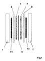
- the cell element of a cell of the invention comprises a pair of bipolar plates (1), a pair of collectors (14), a pair of gasket-frames (8), a pair of electrocatalytic electrodes (7) and an ion exchange membrane (6).
- the bipolar plate (1) is made of a metal plate which may have a flat surface in the area of contact with the collector (14).
- the peripheral frame area of the bipolar plate (1) is provided with holes (2) and optionally with distribution channels (3) for the inlet and outlet of the gases, holes (4) for the passage of the tie-rods (not shown in the figure) and optionally internal ducts (5) for the passage of a suitable cooling means.
- the dimensions of the bipolar plate are therefore dictated by the need to contain a certain active area of membrane (6) and electrodes (7) with the relevant collectors (14), as well as the holes (2, 4) and channels (3).
- the main characteristic of the bipolar plates of the present invention is the possibility of being produced in a great number of pieces with reasonable costs by cutting of commercial sheets or by casting in suitable molds, without any further mechanical flattening of the surface.
- the bipolar plates may be made of aluminum, titanium or alloys thereof, without the need for an electroconductive protective film. This last aspect will be illustrated in further details in the following description. Obviously other metals or alloys that may be used are niobium, tantalum, stainless steels, also high-alloys steels, nickel-chromium alloys, although less cost-effective and heavier due to the higher specific density of these materials.
- the construction material is aluminum or alloys thereof
- the high thermal conductivity permits to withdraw the heat produced during operation of the cell by cooling of the peripheral part of the bipolar plates only.
- the peripheral part is suitably enlarged and the heat removal may be carried out by forced circulation of air or other cooling means (not shown in the figures).
- the bipolar plates (1) made in aluminum or alloys thereof are not to be provided with internal ducts (5), with much simpler construction and a substantial reduction of the costs.
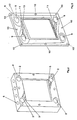
- the gasket-frames (8) comprise holes (9) for inlet and outlet of the reactants and products, fitting with the holes (2) of the bipolar plates (1), and optionally holes (10) for the passage of the tie-rods.
- the holes (10) are not necessary in a possible alternative embodiment where the corners are rounded off.
- the holes (9) are connected to suitable channels (11) cut out in the thickness of the gasket-frame and directed, coupled with channels (3), to uniformly distribute and collect the reactants and the products inside the cell.
- the products outlet should be localized in the lower part to permit an easier purging of the condensate water which may be formed in the cell during operation.
- the two faces of the gasket-frame may be non equivalent as, while the one in contact with the electrodes (7) and the membrane (6) may be flat, the one in contact with the bipolar plates is provided with channels (11) as aforementioned and with ribs (12), that is linear protrusions directed to ensure the necessary sealing to prevent gases from venting outside or mixing inside the cell.
- the sealing on the electrode side is ensured by the intrinsic resiliency of each gasket-frame/membrane pair.
- the gasket-frame is made of an elastomeric castable material. The required resiliency must be sufficient to permit a safe sealing under non-excessive mechanical load to avoid that deformation under compression may obstruct channels (3) and (11) and that the membrane be excessively stressed in the peripheral area.
- the thickness of the gasket-frame is dictated not only by mechanical considerations but also by the need to define an internal space available for the passage of gas.
- the gasket-frame of figs. 3 and 4 is further provided with a step (13) along the inside border to permit a ready housing of the electrode (7) and at the same time ensure a good protection of the membrane (6) from possible irregularities along the periphery of the collectors (14), such as residual peaks or burrs from the cutting of the pieces having the desired dimensions from commercial sheets.
- Fig. 4 shows in more detail the assembly made of gasket-frame (8)/collector (14)/electrode (7).
- the collectors (14) of the present invention are directed to provide at the same time for:
- the collector (14) is represented by a network with a surface provided with terminal sections (15), the efficiency of which has been demonstrated by electric resistance measurements carried out on assemblies simulating a cell element of the cell of the invention comprising two planar plates in aluminum alloy obtained by casting without any further mechanical finish, two collectors made in nickel, 2 mm thick, having a number of voids equal to 100/cm2 (average dimension of the voids : 1 mm), two electrodes commercialized under the trade name of ELAT by E-TEK, U.S.A., holding inbetween a Nafion(R) 117 membrane supplied by Du Pont, U.S.A.
- the measured electrical resistances were in the range of 100-5 milliohm/cm2, with pressures of 0.1-80 kg/cm2 respectively applied to the aluminum plates.
- the measured values are kept constant even maintaining the assembly in steam atmosphere at 100°C, as it may happen during real operation.
- the electrodes of the invention As the deformability of the collectors of the invention is relatively small at the pressure normally applied to the bipolar plates (in the order of some percent fractions of the thickness), it may be assumed that also the electrodes contribute to compensating the planarity deviations of the bipolar plates. In particular, to maintain the stresses on the membranes within acceptable values, the electrodes must exhibit a significant deformability. For this reason, it has been found that the best results in terms of absence of mechanical damages to the membranes are obtained when the electrodes comprise a deformable layer, such as carbon cloth.
- the bipolar plates may be of both the grooved and flat type, the last one being preferred in view of the substantially lower manufacturing cost. As regards the structure of the collector of fig.
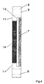
- this tridimensional network may be obtained starting from an expanded foam having open cells in plastic material, such as polyurethane, which is initially pre-treated to obtain a certain electrical conductivity (for example vacuum metallizing or metal deposition by means of electroless baths as known in the art or pyrolysis under inert atmosphere or vacuum to form carbonaceous material, optionally partially graphitized).
- the material, thus pretreated is then subjected to galvanic deposition of the desired metal or alloy, for example nickel, copper or alloys thereof with other metals, up to obtaining the desired thickness.
- the voids of the material have dimensions comprised between 0.1 and 3 mm and the diameter of the metal wires advantageously varies from 0.01 to 1 mm.
- the thickness of the collector indicates the terminal sections of the metal wires which, as above illustrated, ensure for a multiplicity of contact points with a high localized pressure in the small areas represented by the cross-sections of such terminal sections.
- the thickness of the collector is given by the thickness of the gasket-frame decreased by the thickness of the electrode.
- the thickness of the collector is generally comprised between 0.5 and 5 mm and more preferably between 1 and 2 mm.
- the network of fig. 5 is described in EP publication 0266312.A1 which claims its use as an expanded electrode for electrolysis of aqueous diluted solutions of metal ions and in U.S. Patent 4,657,650 which describes its application as the external electrical contact for the connection of elementary cells in an electrolyzer.
- the tridimensional network (reticulated material) according to the present invention may also be used in connection with a metal mesh or graphitized carbon mesh interposed between the reticulated material and the electrode/membrane structure.
- the mesh which may be particularly fine (for example meshes apertures smaller than 1 mm), ensures for the necessary multiplicity of contact points with the electrodes, while the reticulated material may be more freely selected, for example with particularly large voids in order to allow for the maximum percolation of the water which may have condensated inside.
- the use of the mesh permits further to ensure a higher protection of the membrane in the case the reticulated material presents a surface with particularly enhanced spikes.
- the collector of the present invention is simply made of one or more superimposed meshes, made of woven metal wire indicatively having mesh apertures smaller than 3 mm, preferably smaller than 1 mm, in order to ensure for a multiplicity of contact points between the electrodes and the bipolar plates.
- High contact pressures, particularly useful on the bipolar plate side are obtained when the wire used for fabricating the meshes has a quadrangular cross-section but also other polygonal cross-sections may be used.
- the longitudinal edges of the wire, in the superimposed points form a particularly useful array of asperities which imprint the metal surface of the bipolar plate.
- An alternative embodiment of the mesh which is as well advantageous is represented by an expanded metal obtained by pre-cutting of thin sheets and subsequent expansion.
- a mesh is obtained with apertures having various forms, for example rhomboidal, the portions of the metal which define the mesh apertures being rotated with respect to the plane of the sheet itself. Therefore when the expanded metal sheet is pressed against planar surfaces, the peaks of said rotated portions of metal become the areas of contact.
- At least one pair of the above described meshes is used in order to provide for higher resiliency and deformability, permeability to gaseous reactants and percolation of the water condensate.
- the meshes may be characterized by different apertures, in particular a fine mesh size for the one in contact with the electrodes and a coarser mesh in contact with the bipolar plate.
- a further embodiment of the present invention foresees the concurrent use of the above described collectors of the invention and in particular the reticulated material on one membrane side and one or more meshes, optionally having different mesh sizes, on the other side.
- the collector of the present invention made either of reticulated material or of superimposed meshes may be used on one side of the membrane only, while on the other side a rigid, conductive and porous material is used, such as a sinterized metal layer. This must be sufficiently thin in order to comply with the profile of the bipolar plate, which is not perfectly planar, under the applied pressure.
- the void ratio and the dimensions of the pores of the sinterized metal layer must be of the type already described for the collectors of the invention in order to permit the flow of reactants and products, percolation of the water condensate and multiplicity of contact points with the electrodes and bipolar plates.
- the metal forming the collector of the present invention must resist possible aggressive conditions which may be particularly severe when the cell is fed with air on the positive pole compartments and/or with a mixture of carbon dioxide and hydrogen on the negative pole compartments. Under these conditions possible water condensates are acidic.
- the metal is stainless steel of the 18 chromium-10 nickel type, preferably high-alloy steel, nickel-chromium alloys, titanium, niobium, or other valve metals.
- the collectors may be optionally coated with an electroconductive protective film, for example made of platinum group metals or oxides thereof.
- the protective film may be made of conductive polymers of the type comprising intrinsically conductive materials such as polyacethylenes, polypyrroles, polyanylines or the like or plastic materials containing conductive powders (for example graphite powder). Figs.
- each pair of bipolar plates (1) in aluminum or other passivatable material or alloys thereof maintains pressed inside a pair of collectors (14) of the invention, a pair of electrodes (7) and a membrane (6).
- Said electrodes as known in the art, before insertion between the bipolar plates and the collectors, are bonded to the membrane under pressure and heating, possibly after applying to the surface of the electrodes a suspension or solution containing the polymer forming the membrane, with the aim to facilitate both the adhesion of the electrode to the membrane as well as the formation of a large area of triple contact between gas, membrane and catalytic particles of the electrodes.
- the bipolar plates and the collector of the invention do not produce any appreciable improvement of the cell performance with respect to the teachings of the prior art. Therefore, the advantages of the present invention in this case are limited to higher simplicity and lower production costs, in particular for the bipolar plates made of aluminum or other passivatable metals without any protective coating. It has been surprisingly found that the bipolar plates and the collectors of the present invention permit to obtain optimum cell performances also when the electrodes, contrary to what taught in the art, are not previously bonded to the membrane, which obviously permits to reduce the production costs and to limit the risk of damaging the delicate membranes.
- the multiplicity of contact points and the high pressure obtained on said points are capable of maintaining a high percentage of the area of the electrodes in intimate mechanical contact with the membrane.
- the number of catalytic particles embedded in the membrane surface is analogous in the case of the present invention with the electrodes only laying onto the membrane and in the case described in the prior art with the electrodes bonded to the membrane.
- collectors consisting in undulated sheets or simply grooved bipolar plates, as known in the art, the performances are acceptable only when the electrodes are bonded to the membrane.
- the contact areas under sufficiently high pressure are limited only to the crossing points of the grooves or undulations and therefore involve a limited portion of the electrodes surface, which is the only one to be kept in contact with the membrane.
- the contact pressure with the membrane is nil and during operation the differential expansion of the membrane and the electrodes may bring to separation of the surfaces. This remaining portion, therefore, does not contribute in any way to the performance of the cell.
- the optimum results obtained according to the present invention with electrodes not bonded to the membrane are probably due also to a second characteristic of the collectors, that is deformability and residual resiliency under compression.
- This characteristic permits in fact to compensate for the small deviations from planarity of the planar bipolar plates not subjected to mechanical flattening of the surface.
- the compensation of planarity defects permits to maintain a uniformly distributed contact over all the surface of the bipolar plates, of the electrodes and membranes, ensuring thus optimum performances by a homogenous distribution of current.
- the electrodes (7) have a deformable structure.
- Suitable layers are made of carbon cloth or paper, optionally graphitized. The carbon cloth is preferred in view of the higher deformability and flexibility which facilitates handling and assembling into the cell.
- Products of this type containing platinum as the catalyst and polytetrafluoroethylene as the polymeric component are commercialized by various companies, for example E-TEK, U.S.A. under the trade name of ELAT. These products may be utilized as such or after painting with a suspension or paint containing a ionic polymer similar to that forming the membrane.
- Further types of porous layers are made of metal sinterized layers or fine screens or multilayer clothes, for example made of various types of stainless steels, high-alloyed steels, or alloys of nickel, chromium and titanium. Generally multilayer clothes are best preferred in view of their deformability.
- the above layers when made of a multi-layered cloth, may act at the same time as collectors and electrodes. In this case, the aforementioned suspension containing the electrocatalytic particles is applied only to the surface to be put in contact with the membrane.
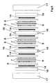
- Fig. 6 describes the assembly made of a multiplicity of cell elements of fig. 1 to form the cell of the invention, comprising the bipolar plates (1), collectors (14), electrodes (7), gasket-frames (8), ion exchange membranes (6), end-plates (18), pressure plates (17).
- the bipolar plates (1) are provided with external connections (16) which, once connected, permit to short-circuit two or more bipolar plates of the cell elements in the case of malfunctioning.
- bipolar plates provided with recesses of suitable form. This type of action permits the safe operation of the cell comprising a high number of cell elements connected in electrical series and it is therefore extremely helpful under a practical point of view.
- Example 1 The same test of Example 1, characterized by utilizing electrodes of the type G and collectors of the type R (sinterized material) was repeated after having made the bipolar plates, end plates and collectors hydrophobic by immersion in a suspension of polytetrafluoroethylene (commercialized by Du Pont under the trade name of Teflon 30N) followed by thermal treatment at 150°C.
- the voltages measured under the same testing conditions of Example 1 resulted comprised between 0,55 and 0,65 Volts. This improvement may be ascribed to the lower tendency of the sinterized material to retain water formed by condensation during operation.
- Example 2 The same cell of Example 1, characterized by the the presence of electrodes of the type G and collectors of the type L was subjected to repeated shortcircuiting of the second cell element by connecting by means of clamps the external connections indicated by reference numeral 16 in fig. 1
- the average voltages of the other cell elements did not change during the shortcircuiting periods and the shortcircuited cell element shortly reached the normal voltage once the clamps were disconnected.
- the maximum voltage between the bipolar plates of the shortcircuited cell element during shortcircuiting resulted in the range of 20-30 mV.
- Two fuel cells were made of three cell elements comprising bipolar plates and end plates provided with grooves directed to act as current distributors and consisting respectively of graphite and aluminum alloy of the type UNI 5076.
- the bipolar plates and terminal plates were further provided with internal ducts for cooling.
- the grooves were oriented in order to be crossed at 90° for each pair of facing sides of the bipolar and end plates.
- the electrodes were of the type G of Example 1 and the membranes were of the type Nafion(R) 117.
- the fuel cell equipped with bipolar plates and terminal plates in graphite and with the electrodes bonded to the membrane was operated under the same conditions as in Example 1 and resulted characterized by the best average voltages referred to the cell elements measured in the various conditions reported in Table 1 (0.7 Volts).
- the same fuel cell, provided with electrodes of the type G not bonded to the membrane showed quite unsatisfactory average voltages, comprised between 0.5 - 0.55 Volts, thus demonstrating that only the collectors of the invention, with their multiplicity of contact points, are capable of ensuring a satisfactory and extended continuity between the surfaces of the membranes and those of the electrodes, when these are not previously bonded.
- the fuel cell comprising grooved bipolar and end plates in aluminum alloy and electrodes of the type G bonded to the membrane, showed quite satisfactory performances at the beginning of the test.
- the voltages rapidly decreased to low values (0.4 Volts) in about a hundred hours, thus demonstrating that only the collectors of the invention are capable of maintaining the contact resistance within negligible values with time.
- a further test was carried out with a fuel cell comprising grooved bipolar and end plates in aluminum alloy, electrodes of the type G (Example 1) not bonded to the membranes and collectors of the invention of the type M (Example 1). The voltage resulted satisfactory (0,60 - 0,65 Volts) and stable with time.
Landscapes
- Chemical & Material Sciences (AREA)
- Engineering & Computer Science (AREA)
- Chemical Kinetics & Catalysis (AREA)
- Electrochemistry (AREA)
- Life Sciences & Earth Sciences (AREA)
- Manufacturing & Machinery (AREA)
- Sustainable Development (AREA)
- Sustainable Energy (AREA)
- General Chemical & Material Sciences (AREA)
- Composite Materials (AREA)
- Metallurgy (AREA)
- Organic Chemistry (AREA)
- Materials Engineering (AREA)
- Fuel Cell (AREA)
- Manufacture Of Macromolecular Shaped Articles (AREA)
- Electrolytic Production Of Non-Metals, Compounds, Apparatuses Therefor (AREA)
- Inert Electrodes (AREA)
- Electrodes For Compound Or Non-Metal Manufacture (AREA)
- Primary Cells (AREA)
- Secondary Cells (AREA)
- Separation Using Semi-Permeable Membranes (AREA)
Claims (23)
- Zellenelement für eine Brennstoffzelle oder zur Elektrolyse von reinem Wasser oder zum Aufkonzentrieren von Wasserstoff und Sauerstoff aus gasförmigen Reaktionsteilnehmern, umfassend:ein Paar Bipolar- oder Endplatten (1,18), die mit Löchern (2) zur Zufuhr von Reaktionsteilnehmern und zum Entfernen von Produkten und restlichen Reaktionsteilnehmern versehen sind, wobei die Bipolar- oder Endplatten (1,18) aus Metallen oder Metalllegierungen bestehen, die ein Schutzoxid ausbilden können, ausgewählt aus der Gruppe bestehend aus Aluminium, Titan, Zirkon, Niob, Tantal und Legierungen dieser Metalle, Edelstählen, hochlegierten Stählen, Chrom-Nickel-Legierungen,eine Ionenaustauschmembran (6),ein Paar elektrokatalytischer, poröser Elektroden (7), welche eine verformbare Schicht umfassen, die so ausgelegt ist, dass eine mechanische Beschädigung der Membran (6) verhindert wird,ein Paar Dichtungsrahmen (8)ein Paar poröser Stromkollektoren (14), die mit zahlreichen Kontaktpunkten für den elektrischen Kontakt zwischen den Bipolar- oder Endplatten (1,18) und den Elektroden (7) versehen sind, wobei wenigstens einer dieser porösen Stromkollektoren (14) aus einem nachgiebigen Material besteht, welches Hohlräume mit Abmessungen zwischen 0,1 und 3 mm aufweist und unter einem Druck zwischen 0,1 und 80 kg/cm2 eine Restverformbarkeit und -elastizität aufweist,wobei die zahlreichen Kontaktpunkte der Stromkollektoren (14) bei diesem Druck ein Aufbrechen des Schutzoxids der Bipolar- oder Endplatten (1,18) ermöglichen oder dessen Wachstum verhindern.
- Element gemäß Anspruch 1, wobei der Kollektor (14), welcher eine Restverformbarkeit und -elastizität aufweist, ein dreidimensionales Netzwerk aus Metalldrähten ist, wobei die Oberfläche des Netzwerkes die Endabschnitte (15) wenigstens eines Teils dieser Drähte umfasst.
- Element gemäß Anspruch 2, wobei das dreidimensionale Netzwerk eine Porösität von wenigstens 50% aufweist und wobei der Durchmesser der Metalldrähte zwischen 0,01 und 1 mm beträgt.
- Element gemäß einem der Ansprüche 1 bis 3, wobei der Kollektor (14), welcher eine Restverformbarkeit und -elastizität aufweist, aus wenigstens zwei übereinanderliegenden Gittern besteht.
- Element gemäß Anspruch 4, wobei die Gitter unterschiedliche Maschenweiten aufweisen, mit feineren Maschen für das mit den Elektroden (7) in Kontakt stehende Gitter und gröberen Maschen für das mit den Bipolar- oder Endplatten (1,18) in Kontakt stehende Gitter
- Element gemäß einem der Ansprüche 4 oder 5, wobei die Gitter ausgewählt sind aus der Gruppe bestehend aus Drahtgeweben und expandierten Metallblechen.
- Element gemäß Anspruch 6, wobei die Metalldrähte einen polygonalen Querschnitt aufweisen.
- Element gemäß einem der Ansprüche 1 bis 3, wobei der Kollektor (14), welcher eine Restverformbarkeit und -elastizität aufweist, aus einer Matte aus ineinander verschlungenen helixartigen Spiralen oder einem Mehrschichttuch besteht.
- Element gemäß einem der Ansprüche 1 bis 8, wobei beide Kollektoren (14) eine Restverformbarkeit und -elastizität aufweisen oder wobei ein Kollektor (14) eine Restverformbarkeit und -elastizität aufweist und der andere Kollektor (14) ein starres poröses Blech, vorzugsweise eine gesinterte Metallschicht ist.
- Element gemäß einem der Ansprüche 1 bis 9, wobei die Kollektoren (14) eine Dicke zwischen 0,5 und 5 mm aufweisen.
- Element gemäß einem der Ansprüche 1 bis 3 oder 8 bis 10, wobei die Kollektoren (14) außerdem ein feines Metallgitter umfassen, das zu den Elektroden (7) hin angeordnet ist.
- Element gemäß einem der Ansprüche 1 bis 11, wobei die Kollektoren (14) aus einem korrosionsbeständigen Material bestehen, das ausgewählt ist aus der Gruppe bestehend aus Edelstählen, hochlegierten Stählen, Chrom-Nickel-Legierungen.
- Element gemäß einem der Ansprüche 1 bis 12, wobei die Kollektoren (14) und die Bipolar- oder Endplatten (1,18) hydrophob sind.
- Element gemäß einem der Ansprüche 1 bis 13, wobei die Bipolar- oder Endplatten (1,18) eine ebene Oberfläche aufweisen,wobei die Bipolar- oder Endplatten (1,18) bevorzugt durch Formen oder Schneiden kommerzieller Bleche ohne weitere Oberflächenbehandlung oder mit Vertiefungen in der Oberfläche hergestellt werden,wobei die Bipolar- oder Endplatten (1,18) vorzugsweise außerdem mit Kanälen (3) zum Verteilen und Entfernen der Reaktionsteilnehmer und Produkte versehen sind,wobei die Bipolar- oder Endplatten (1,18) vorzugsweise außerdem mit internen Leitungen (5) zum Kühlen mit Gasen oder Flüssigkeiten versehen sind,und wobei die Außenabmessungen der Bipolar- oder Endplatten (1,18) vorzugsweise vergrößert sind, um ein Kühlen mit Gasen oder Flüssigkeiten zu ermöglichen.
- Element gemäß einem der Ansprüche 1 bis 14, wobei die Bipolar- oder Endplatten (1,18) aus einem Material hergestellt sind, das ausgewählt ist aus der Gruppe bestehend aus Aluminium, Titan, Zirkon, Niob, Tantal und Legierungen dieser Metalle, und wobei der Kontaktwiderstand zwischen den Bipolar- oder Endplatten (1,18) und den Kollektoren (14) bei dem genannten Druck zwischen 100 und 5 mΩ·cm2 liegt.
- Element gemäß einem der Ansprüche 1 bis 15, wobei die Dichtungsrahmen (8) aus einem gießfähigen elastomeren Material bestehen und Löcher (9) für die Verteilung und das Entfernen von Reaktionsteilnehmern und Produkten und eine Stufe (13) zur Aufnahme der Elektroden (7) und Rippen (12) zum Abdichten und zum Trennen der Reaktionsteilnehmer und der Produkte umfassen.
- Element gemäß einem der Ansprüche 1 bis 16, wobei die Elektroden (7) aus einer porösen, leitfähigen Schicht hergestellt sind, welche eine Oberfläche mit einem Katalysator und eine Oberfläche mit hydrophobem Material aufweist.
- Element gemäß einem der Ansprüche 1 bis 17, wobei die verformbare Schicht ein flexibles Kohlenstofftuch, Kohlenstoffpapier oder ein flexibles Tuch eines korrosionsbeständigen Metalls ist, welches ausgewählt ist aus der Gruppe bestehend aus Edelstählen, hochlegierten Stählen, Chrom-Nickel-Stählen.
- Element gemäß einem der Ansprüche 17 oder 18, wobei die Elektroden (7) außerdem mit einer Polymerbeschichtung versehen sind, die Ionenaustauscheigenschaften aufweist und die auf die katalysatorhaltige Oberfläche aufgetragen ist.
- Element gemäß einem der Ansprüche 1 bis 19, wobei die Elektroden (7) vor dem Zusammenbau der elektrochemischen Zelle nicht mit der Membran verbunden werden.
- Element gemäß einem der Ansprüche 1 bis 19, wobei die Elektroden (7) vor dem Zusammenbau der elektrochemischen Zelle mit der Membran verbunden werden und eine einheitliche Struktur bilden.
- Element gemäß einem der Ansprüche 1 bis 21, wobei die Bipolar- oder Endplatten (1,18) mit externen Anschlüssen oder Vorsprüngen (16) zum Kurzschließen versehen sind.
- Brennstoffzelle, welche das Zellenelement gemäß einem der Ansprüche 1 bis 22 umfasst.
Applications Claiming Priority (2)
| Application Number | Priority Date | Filing Date | Title |
|---|---|---|---|
| ITMI930857 | 1993-04-30 | ||
| ITMI930857A IT1270878B (it) | 1993-04-30 | 1993-04-30 | Migliorata cella elettrochimica utilizzante membrane a scambio ionico e piatti bipolari metallici |
Publications (2)
| Publication Number | Publication Date |
|---|---|
| EP0629015A1 EP0629015A1 (de) | 1994-12-14 |
| EP0629015B1 true EP0629015B1 (de) | 2001-12-05 |
Family
ID=11365953
Family Applications (1)
| Application Number | Title | Priority Date | Filing Date |
|---|---|---|---|
| EP94106748A Expired - Lifetime EP0629015B1 (de) | 1993-04-30 | 1994-04-29 | Elektrochemische Zelle mit Ionen-Austauschmembranen und metallischen bipolaren Platten |
Country Status (16)
| Country | Link |
|---|---|
| US (3) | US5482792A (de) |
| EP (1) | EP0629015B1 (de) |
| JP (1) | JP2953555B2 (de) |
| CN (1) | CN1076887C (de) |
| AT (1) | ATE210339T1 (de) |
| AU (1) | AU674931B2 (de) |
| BR (1) | BR9401641A (de) |
| CA (1) | CA2121455C (de) |
| CZ (1) | CZ98694A3 (de) |
| DE (1) | DE69429304T2 (de) |
| DK (1) | DK0629015T3 (de) |
| ES (1) | ES2169050T3 (de) |
| FI (1) | FI941932A (de) |
| IT (1) | IT1270878B (de) |
| RU (1) | RU2126569C1 (de) |
| SK (1) | SK50694A3 (de) |
Families Citing this family (249)
| Publication number | Priority date | Publication date | Assignee | Title |
|---|---|---|---|---|
| US5773162A (en) * | 1993-10-12 | 1998-06-30 | California Institute Of Technology | Direct methanol feed fuel cell and system |
| US6703150B2 (en) * | 1993-10-12 | 2004-03-09 | California Institute Of Technology | Direct methanol feed fuel cell and system |
| US5599638A (en) * | 1993-10-12 | 1997-02-04 | California Institute Of Technology | Aqueous liquid feed organic fuel cell using solid polymer electrolyte membrane |
| US6042702A (en) * | 1993-11-22 | 2000-03-28 | E.I. Du Pont De Nemours And Company | Electrochemical cell having a current distributor comprising a conductive polymer composite material |
| US5961795A (en) * | 1993-11-22 | 1999-10-05 | E. I. Du Pont De Nemours And Company | Electrochemical cell having a resilient flow field |
| JPH0817451A (ja) * | 1994-06-29 | 1996-01-19 | Aisin Seiki Co Ltd | 燃料電池 |
| JPH08130023A (ja) * | 1994-10-27 | 1996-05-21 | Aisin Seiki Co Ltd | 燃料電池 |
| WO1996019015A2 (en) * | 1994-12-17 | 1996-06-20 | Loughborough University Innovations Limited | Galvanic and fuel cell arrangements |
| WO1996035001A1 (en) * | 1995-05-01 | 1996-11-07 | E.I. Du Pont De Nemours And Company | Electrochemical cell having a resilient flow field |
| AU4421296A (en) * | 1995-05-01 | 1996-11-21 | E.I. Du Pont De Nemours And Company | Electrochemical cell having a current distributor comprising a conductive polymer composite material |
| DE19533773A1 (de) * | 1995-09-12 | 1997-03-13 | Basf Ag | Plattenstapelzelle |
| US6312845B1 (en) | 1995-10-06 | 2001-11-06 | The Dow Chemical Company | Macroporous flow field assembly |
| US5702755A (en) * | 1995-11-06 | 1997-12-30 | The Dow Chemical Company | Process for preparing a membrane/electrode assembly |
| DE69629201D1 (de) * | 1995-10-06 | 2003-08-28 | Dow Global Technologies Inc | Fluessigkeitsverteilungsstrukturen fuer membran-elektrode-anordnungen von brennstoffzellen |
| US5624769A (en) * | 1995-12-22 | 1997-04-29 | General Motors Corporation | Corrosion resistant PEM fuel cell |
| US5882810A (en) * | 1996-03-08 | 1999-03-16 | The Dow Chemicalcompany | Active layer for membrane electrode assembly |
| AUPN876896A0 (en) * | 1996-03-18 | 1996-04-18 | Ceramic Fuel Cells Limited | An electrical interconnect for a planar fuel cell |
| US6054228A (en) * | 1996-06-06 | 2000-04-25 | Lynntech, Inc. | Fuel cell system for low pressure operation |
| IT1284072B1 (it) * | 1996-06-26 | 1998-05-08 | De Nora Spa | Cella elettrochimica a membrana provvista di elettrodi a diffusione gassosa contattati da portacorrente metallici lisci e porosi a |
| US5868918A (en) * | 1996-09-26 | 1999-02-09 | Air Products And Chemicals, Inc. | Method for separating oxygen from an oxygen-containing gas |
| US5798187A (en) * | 1996-09-27 | 1998-08-25 | The Regents Of The University Of California | Fuel cell with metal screen flow-field |
| IT1284887B1 (it) * | 1996-10-03 | 1998-05-22 | De Nora Spa | Metodo di esclusione di una cella elementare malfunzionante di un elettrolizzatore o di un generatore elettrochimico a membrana |
| US6037075A (en) * | 1996-11-26 | 2000-03-14 | United Technologies Corporation | Electrically non-conductive plate structures and high pressure electrochemical cell devices employing same |
| DK0963615T3 (da) | 1997-01-22 | 2003-10-06 | Siemens Ag | Brændselscelle og anvendelse af jern-baserede legeringer til konstruktion af brændselsceller |
| US6146780A (en) * | 1997-01-24 | 2000-11-14 | Lynntech, Inc. | Bipolar separator plates for electrochemical cell stacks |
| US6287431B1 (en) | 1997-03-21 | 2001-09-11 | Lynntech International, Ltd. | Integrated ozone generator system |
| US5989407A (en) * | 1997-03-31 | 1999-11-23 | Lynntech, Inc. | Generation and delivery device for ozone gas and ozone dissolved in water |
| US6576096B1 (en) | 1998-01-05 | 2003-06-10 | Lynntech International, Ltd. | Generation and delivery device for ozone gas and ozone dissolved in water |
| KR20010006129A (ko) * | 1997-04-07 | 2001-01-26 | 그래햄 이. 테일러 | 산소 음극 시스템을 사용하는 알칼리 금속 할라이드 염수의 전기분해법 |
| US5976726A (en) | 1997-05-01 | 1999-11-02 | Ballard Power Systems Inc. | Electrochemical cell with fluid distribution layer having integral sealing capability |
| EP0996988A1 (de) * | 1997-05-13 | 2000-05-03 | Loughborough University Innovations Limited | Stromverteilern aus gesinterten metallen und diese benutzende brennstoffzellen |
| IT1293814B1 (it) * | 1997-08-04 | 1999-03-10 | De Nora Spa | Cella a combustibile a membrana a scambio ionico con raffreddamento periferico |
| AU2724899A (en) * | 1998-02-10 | 1999-08-30 | H2-Interpower Gmbh | Fuel cell with solid electrolyte and planar structure |
| US6232010B1 (en) | 1999-05-08 | 2001-05-15 | Lynn Tech Power Systems, Ltd. | Unitized barrier and flow control device for electrochemical reactors |
| US6071635A (en) * | 1998-04-03 | 2000-06-06 | Plug Power, L.L.C. | Easily-formable fuel cell assembly fluid flow plate having conductivity and increased non-conductive material |
| US6007933A (en) * | 1998-04-27 | 1999-12-28 | Plug Power, L.L.C. | Fuel cell assembly unit for promoting fluid service and electrical conductivity |
| WO2000001025A1 (fr) * | 1998-06-30 | 2000-01-06 | Matsushita Electric Industrial Co., Ltd. | Pile a combustible electrolytique en polymere solide |
| EP1026768A1 (de) | 1998-07-10 | 2000-08-09 | Kabushiki Kaisha Toyota Chuo Kenkyusho | Separator für brennstoffzelle und dessen herstellung |
| JP2000106197A (ja) * | 1998-09-30 | 2000-04-11 | Aisin Takaoka Ltd | 燃料電池及び燃料電池用セパレータ |
| US6261710B1 (en) | 1998-11-25 | 2001-07-17 | Institute Of Gas Technology | Sheet metal bipolar plate design for polymer electrolyte membrane fuel cells |
| JP2000164225A (ja) * | 1998-11-25 | 2000-06-16 | Toshiba Corp | 固体高分子電解質型燃料電池のセパレータおよびその製造方法 |
| US6602631B1 (en) | 1999-01-26 | 2003-08-05 | Lynntech Power Systems, Ltd. | Bonding electrochemical cell components |
| US6280866B1 (en) | 1999-02-23 | 2001-08-28 | Northern Research & Engineering Corporation | Fuel cell flow distributor design for improving durability and performance |
| US6284401B1 (en) * | 1999-04-19 | 2001-09-04 | George A. Marchetti | Thin graphite bipolar plate with associated gaskets and carbon cloth flow-field for use in an ionomer membrane fuel cell |
| ITMI991090A1 (it) * | 1999-05-18 | 2000-11-18 | De Nora Spa | Dispositivo di umidificazione per celle a combustibile a membrana polimerica |
| US6503654B2 (en) * | 1999-05-19 | 2003-01-07 | George A. Marchetti | Thin graphite bipolar plate with associated gaskets and carbon cloth flow-field for use in an ionomer membrane fuel cell |
| GB9915925D0 (en) * | 1999-07-08 | 1999-09-08 | Univ Loughborough | Flow field plates |
| FR2799308B1 (fr) * | 1999-09-30 | 2002-01-25 | Sorapec | Perfectionnements apportes aux collecteurs bipolaires pour pile a combustible de type pem |
| US6383677B1 (en) | 1999-10-07 | 2002-05-07 | Allen Engineering Company, Inc. | Fuel cell current collector |
| US6649031B1 (en) | 1999-10-08 | 2003-11-18 | Hybrid Power Generation Systems, Llc | Corrosion resistant coated fuel cell bipolar plate with filled-in fine scale porosities and method of making the same |
| US6864007B1 (en) | 1999-10-08 | 2005-03-08 | Hybrid Power Generation Systems, Llc | Corrosion resistant coated fuel cell plate with graphite protective barrier and method of making the same |
| US6315958B1 (en) * | 1999-11-10 | 2001-11-13 | Wisconsin Alumni Research Foundation | Flow cell for synthesis of arrays of DNA probes and the like |
| US6777126B1 (en) | 1999-11-16 | 2004-08-17 | Gencell Corporation | Fuel cell bipolar separator plate and current collector assembly and method of manufacture |
| IT1314256B1 (it) * | 1999-12-03 | 2002-12-06 | Nora Fuel Cells S P A De | Batteria di celle a combustibile a membrana polimerica. |
| US6372376B1 (en) * | 1999-12-07 | 2002-04-16 | General Motors Corporation | Corrosion resistant PEM fuel cell |
| WO2001045192A1 (en) * | 1999-12-16 | 2001-06-21 | Proton Energy Systems, Inc. | Low gravity electrochemical cell |
| US7153409B2 (en) * | 1999-12-16 | 2006-12-26 | Proton Energy Systems, Inc. | Electrochemical cell system and method of operation |
| DE19960815A1 (de) * | 1999-12-16 | 2001-07-19 | Siemens Ag | Brennstoffzellenblock |
| WO2001054218A2 (en) * | 2000-01-19 | 2001-07-26 | Manhattan Scientifics, Inc. | Fuel cell stack with cooling fins and use of expanded graphite in fuel cells |
| US6770394B2 (en) * | 2000-02-11 | 2004-08-03 | The Texas A&M University System | Fuel cell with monolithic flow field-bipolar plate assembly and method for making and cooling a fuel cell stack |
| US6828054B2 (en) | 2000-02-11 | 2004-12-07 | The Texas A&M University System | Electronically conducting fuel cell component with directly bonded layers and method for making the same |
| WO2001059862A2 (en) * | 2000-02-11 | 2001-08-16 | The Texas A & M University System | Electroconductive fuel cell component with directly bonded layers and method for making same |
| US6602626B1 (en) | 2000-02-16 | 2003-08-05 | Gencell Corporation | Fuel cell with internal thermally integrated autothermal reformer |
| WO2001071842A2 (en) | 2000-03-17 | 2001-09-27 | Allen Engineering Company, Inc. | Fuel cell stack assembly |
| DE10015360B4 (de) * | 2000-03-28 | 2006-11-23 | Ballard Power Systems Inc., Burnaby | Separatoreinheit für Elektrolysezellen und Brennstoffzellen |
| WO2001075997A1 (en) * | 2000-03-31 | 2001-10-11 | Ingersoll-Rand Energy Systems Corporation | Fuel cell flow distributor design for improving durability and performance |
| EP1160900A3 (de) * | 2000-05-26 | 2007-12-12 | Kabushiki Kaisha Riken | Geprägter Stromkollektor-Separator für elektrochemische Brennstoffzelle |
| US20020045081A1 (en) * | 2000-07-05 | 2002-04-18 | Masaaki Nanaumi | Electrolyte membrane/electrode assembly of solid polymer electrolyte fuel cell |
| SE522666C2 (sv) * | 2000-07-07 | 2004-02-24 | Volvo Ab | Gasfördelningselement för bränsleceller, bränslecell samt metod för att tillverka ett gasfördelningselement |
| WO2002015302A2 (en) | 2000-08-14 | 2002-02-21 | World Properties Inc. | Thermosetting composition for electrochemical cell components and methods of making thereof |
| US20020022382A1 (en) * | 2000-08-18 | 2002-02-21 | Franklin Jerrold E. | Compliant electrical contacts for fuel cell use |
| US6531238B1 (en) | 2000-09-26 | 2003-03-11 | Reliant Energy Power Systems, Inc. | Mass transport for ternary reaction optimization in a proton exchange membrane fuel cell assembly and stack assembly |
| WO2002043176A1 (en) * | 2000-11-22 | 2002-05-30 | Powercell Corporation | Bipolar plate and method of manufacturing same |
| DE60139575D1 (de) * | 2000-12-12 | 2009-09-24 | Tersano Inc | Vorrichtung zur erzeugung und applikation von ozonisiertem wasser |
| US20020155333A1 (en) * | 2001-01-19 | 2002-10-24 | Fitts Bruce B. | Apparatus and method for electrochemical cell components |
| US7138203B2 (en) * | 2001-01-19 | 2006-11-21 | World Properties, Inc. | Apparatus and method of manufacture of electrochemical cell components |
| US6824910B2 (en) * | 2001-01-24 | 2004-11-30 | The Regents Of The University Of California | Co-flow planar SOFC fuel cell stack |
| ITMI20010458A1 (it) * | 2001-03-06 | 2002-09-06 | Nuvera Fuel Cells Europ Srl | Metodo di cortocircuitazione di una cella elettrochimica elementare malfunzionante di una struttura filtro-pressa |
| RU2183370C1 (ru) | 2001-04-12 | 2002-06-10 | ЗАО Индепендент Пауэр Технолоджис "ИПТ" | Модуль топливных элементов и батарея на его основе |
| US6878477B2 (en) * | 2001-05-15 | 2005-04-12 | Hydrogenics Corporation | Fuel cell flow field plate |
| US6852439B2 (en) * | 2001-05-15 | 2005-02-08 | Hydrogenics Corporation | Apparatus for and method of forming seals in fuel cells and fuel cell stacks |
| US20050095492A1 (en) * | 2001-05-15 | 2005-05-05 | Hydrogenics Corporation | Fuel cell stack |
| FI20011044A (fi) * | 2001-05-17 | 2002-11-18 | Reijo Varila | Elektrolyyttinen kenno, kennorakenne sekä kennorakenteen käytöt |
| US6884531B2 (en) * | 2001-05-21 | 2005-04-26 | Saudi Arabian Oil Company | Liquid hydrocarbon based fuels for fuel cell on-board reformers |
| US6620542B2 (en) | 2001-05-30 | 2003-09-16 | Hewlett-Packard Development Company, L.P. | Flex based fuel cell |
| JPWO2003012903A1 (ja) * | 2001-07-31 | 2004-11-25 | 住友精密工業株式会社 | 燃料電池 |
| US6781249B2 (en) | 2001-08-29 | 2004-08-24 | Hewlett-Packard Development Company, L.P. | Retrofittable power supply |
| JP3860733B2 (ja) * | 2001-09-17 | 2006-12-20 | 新光電気工業株式会社 | 燃料電池 |
| ITMI20012342A1 (it) * | 2001-11-08 | 2003-05-08 | Nuvera Fuel Cells Europ Srl | Metodo per riutilizzare collettori/distributori di corrente di un generatore elettrochimico a membrana |
| US6811918B2 (en) * | 2001-11-20 | 2004-11-02 | General Motors Corporation | Low contact resistance PEM fuel cell |
| DE10158771C2 (de) * | 2001-11-23 | 2003-09-18 | Reinz Dichtungs Gmbh & Co Kg | Brennstoffzellensystem |
| KR100429685B1 (ko) * | 2001-12-17 | 2004-05-03 | 한국과학기술연구원 | 소형 고분자 전해질 연료전지용 다공성 가스분배판, 및 이를 포함하여 제조된 분리판 |
| DE10162871A1 (de) * | 2001-12-20 | 2003-07-10 | Forschungszentrum Juelich Gmbh | Bipolare Platte aus Graphit |
| KR100448168B1 (ko) * | 2001-12-27 | 2004-09-10 | 현대자동차주식회사 | 연료전지용 막-전극-가스켓 접합체의 제조방법 |
| EP1327492A1 (de) * | 2002-01-15 | 2003-07-16 | N.V. Bekaert S.A. | Poröser Metallstapel für Brennstoffzellen oder Elektrolyseure |
| EP1328030A1 (de) * | 2002-01-15 | 2003-07-16 | N.V. Bekaert S.A. | Metallstapel für Brennstoffzellen oder Elektrolyseure |
| WO2003075384A1 (fr) * | 2002-03-04 | 2003-09-12 | Mitsubishi Materials Corporation | Pile a combustible en oxyde solide et separateur |
| DE10216306B4 (de) * | 2002-04-14 | 2008-06-12 | Sgl Carbon Ag | Verfahren zur Herstellung einer Kontaktplatte für eine elektrochemische Zelle sowie deren Verwendungen |
| ITMI20020869A1 (it) | 2002-04-23 | 2003-10-23 | Nuvera Fuel Cells Europ Srl | Generatore elettrochimico e membrana a ingombro ridotto |
| US6926986B2 (en) * | 2002-04-29 | 2005-08-09 | Energy Conversion Devices | Fuel cell with encapsulated electrodes |
| US6828057B2 (en) * | 2002-04-29 | 2004-12-07 | Energy Conversion Devices, Inc. | Fuel cell with framed electrodes |
| US6989216B2 (en) * | 2002-04-29 | 2006-01-24 | Texaco Ovonic Fuel Cell Llc | Fuel cell with overmolded electrode assemblies |
| US7241334B2 (en) * | 2002-05-23 | 2007-07-10 | Columbian Chemicals Company | Sulfonated carbonaceous materials |
| EP1514322A2 (de) * | 2002-05-31 | 2005-03-16 | Lynntech, Inc. | Elektrochemische zelle und bipolar-satz für eine elektrochemische zelle |
| ITMI20021338A1 (it) * | 2002-06-17 | 2003-12-17 | Nuvera Fuel Cells Europ Srl | Generatore elettrochimico a membrana con iniezione diretta di acqua liquida nei agenti gassosi |
| US7270906B2 (en) * | 2002-06-24 | 2007-09-18 | Delphi Technologies, Inc. | Solid-oxide fuel cell module for a fuel cell stack |
| DE10233982B4 (de) * | 2002-07-25 | 2007-08-16 | Forschungszentrum Jülich GmbH | Bipolare Platte für eine Brennstoffzelle und Brennstoffzellenstapel |
| US6838202B2 (en) * | 2002-08-19 | 2005-01-04 | General Motors Corporation | Fuel cell bipolar plate having a conductive foam as a coolant layer |
| TWI241732B (en) * | 2002-09-25 | 2005-10-11 | E I Du Pont Canada Company | Mesh reinforced fuel cell separator plate |
| JP4396091B2 (ja) * | 2002-09-30 | 2010-01-13 | 三菱マテリアル株式会社 | 燃料電池用ガス拡散層 |
| US7001687B1 (en) | 2002-10-04 | 2006-02-21 | The Texas A&M University System | Unitized MEA assemblies and methods for making same |
| US7005209B1 (en) | 2002-10-04 | 2006-02-28 | The Texas A&M University System | Fuel cell stack assembly |
| US20040166397A1 (en) * | 2002-11-08 | 2004-08-26 | Valdez Thomas I. | Cathode structure for direct methanol fuel cell |
| JP3793141B2 (ja) * | 2002-11-14 | 2006-07-05 | 株式会社日立製作所 | 固体高分子形燃料電池及びセパレータ |
| GB0227180D0 (en) * | 2002-11-21 | 2002-12-24 | Omnagen Ltd | Improvements in or relating to a fuel cell |
| US7282291B2 (en) * | 2002-11-25 | 2007-10-16 | California Institute Of Technology | Water free proton conducting membranes based on poly-4-vinylpyridinebisulfate for fuel cells |
| US6887613B2 (en) * | 2002-12-04 | 2005-05-03 | General Motors Corporation | Corrosion resistant PEM fuel cell |
| US7736783B2 (en) * | 2002-12-04 | 2010-06-15 | Lynntech, Inc. | Very thin, light bipolar plates |
| AU2003294576A1 (en) * | 2002-12-04 | 2004-06-23 | Lynntech Power Systems, Ltd. | Self-aligning components for electrochemical cells |
| DE10260149A1 (de) | 2002-12-20 | 2004-07-01 | BSH Bosch und Siemens Hausgeräte GmbH | Vorrichtung zur Bestimmung des Leitwertes von Wäsche, Wäschetrockner und Verfahren zur Verhinderung von Schichtbildung auf Elektroden |
| US7294425B2 (en) * | 2002-12-23 | 2007-11-13 | Semgreen, L.P. | Channel-less proton exchange membrane fuel cell |
| US6772617B1 (en) | 2003-01-24 | 2004-08-10 | Gencell Corporation | Method and apparatus for in-situ leveling of progressively formed sheet metal |
| US6793544B2 (en) | 2003-02-05 | 2004-09-21 | General Motors Corporation | Corrosion resistant fuel cell terminal plates |
| US20040247990A1 (en) * | 2003-03-19 | 2004-12-09 | Campbell Stephen A. | Platinum alloy catalysts for electrochemical fuel cells |
| JP4441719B2 (ja) * | 2003-03-20 | 2010-03-31 | 大日本印刷株式会社 | 燃料電池用セパレータ |
| US20040191603A1 (en) * | 2003-03-25 | 2004-09-30 | Kaiser Joseph G. | Clad metallic bipolar plates and electricity-producing systems and fuel cells using the same |
| US7407721B2 (en) * | 2003-04-15 | 2008-08-05 | Mti Microfuel Cells, Inc. | Direct oxidation fuel cell operating with direct feed of concentrated fuel under passive water management |
| US7282293B2 (en) * | 2003-04-15 | 2007-10-16 | Mti Microfuel Cells Inc. | Passive water management techniques in direct methanol fuel cells |
| US20050019646A1 (en) * | 2003-05-16 | 2005-01-27 | Joos Nathaniel Ian | Complementary active-surface feed flow |
| DE10323881A1 (de) * | 2003-05-26 | 2004-12-23 | Siemens Ag | Kontaktvorrichtung sowie Brennstoffzellenstapel bzw. Brennstoffzellenblock mit einer derartigen Kontaktvorrichtung |
| US7655337B2 (en) * | 2003-06-27 | 2010-02-02 | Ultracell Corporation | Micro fuel cell thermal management |
| US6942941B2 (en) * | 2003-08-06 | 2005-09-13 | General Motors Corporation | Adhesive bonds for metalic bipolar plates |
| US20050037935A1 (en) * | 2003-08-11 | 2005-02-17 | Abd Elhamid Mahmoud H. | Composition and method for surface treatment of oxidized metal |
| US7396559B2 (en) * | 2003-08-11 | 2008-07-08 | General Motors Corporation | Method of making an electrically conductive element for use in a fuel cell |
| US20050069749A1 (en) * | 2003-08-15 | 2005-03-31 | David Frank | Flow field plate arrangement |
| US7358005B2 (en) * | 2003-09-18 | 2008-04-15 | General Electric Company | Methods and apparatus for isolating solid oxide fuel cells |
| JP2007505998A (ja) * | 2003-09-22 | 2007-03-15 | ハイドロジェニクス コーポレイション | 電解槽セルの配置 |
| WO2005028715A1 (en) * | 2003-09-22 | 2005-03-31 | Hydrogenics Corporation | System and method for alarm recovery for an electrolyzer cell module |
| US20050186458A1 (en) * | 2003-09-22 | 2005-08-25 | Ali Rusta-Sallehy | Electrolyzer cell stack system |
| US20050064270A1 (en) * | 2003-09-24 | 2005-03-24 | Marianowski Leonard G. | Fuel cell bipolar separator plate |
| ITMI20031881A1 (it) * | 2003-10-01 | 2005-04-02 | Nuvera Fuel Cells Europ Srl | Separatore bipolare per batteria di celle a combustibile. |
| ITMI20031972A1 (it) * | 2003-10-14 | 2005-04-15 | Nuvera Fuel Cells Europ Srl | Cella a combustibile a membrana con funzionamento stabile nel tempo |
| JP4154315B2 (ja) * | 2003-11-21 | 2008-09-24 | 本田技研工業株式会社 | 燃料電池 |
| ITMI20032531A1 (it) * | 2003-12-19 | 2005-06-20 | Nuvera Fuel Cells Europ Srl | Cella a combustione a membrana alimentata in |
| FR2866477B1 (fr) * | 2004-02-17 | 2006-06-30 | Air Liquide | Architecture de pile a combustible |
| US7150918B2 (en) * | 2004-02-27 | 2006-12-19 | General Motors Corporation | Bilayer coating system for an electrically conductive element in a fuel cell |
| JP4696456B2 (ja) * | 2004-03-15 | 2011-06-08 | 日立電線株式会社 | 燃料電池セパレータ用耐蝕導電性複合材料 |
| GB2413002B (en) * | 2004-04-08 | 2006-12-06 | Intelligent Energy Ltd | Fuel cell gas distribution |
| DE102004028141C5 (de) * | 2004-06-10 | 2015-11-19 | Elcomax Membranes Gmbh | Membran-Elektroden-Modul (MEA) für eine Brennstoffzelle und Brennstoffzellenstapel |
| JP4908778B2 (ja) * | 2004-06-30 | 2012-04-04 | キヤノン株式会社 | 固体高分子型燃料電池の触媒層の製造方法および固体高分子型燃料電池の製造方法 |
| US7569303B2 (en) | 2004-09-24 | 2009-08-04 | Hydrogenics Corporation | Membrane electrode assembly with modified catalyst layout |
| US7378177B2 (en) * | 2004-09-30 | 2008-05-27 | Proton Energy Systems, Inc. | Electrochemical cell bipolar plate |
| US7951510B2 (en) | 2004-11-11 | 2011-05-31 | GM Global Technology Operations LLC | Electroconductive polymer coating on electroconductive elements in a fuel cell |
| US7452623B2 (en) * | 2004-11-11 | 2008-11-18 | Proton Energy Systems, Inc. | Electrochemical cell bipolar plate with sealing feature |
| ITMI20042247A1 (it) * | 2004-11-19 | 2005-02-19 | Nuvera Fuel Cells Europ Srl | Sistema di generasione elettrica comprendente celle a combustibile a membrana alimentate con gas secchi |
| CA2589172C (en) * | 2004-11-25 | 2011-03-22 | Kabushiki Kaisha Toshiba | Fuel cell comprising one integrated insulating film folded in two over a membrane electrode assembly |
| US7687176B2 (en) * | 2004-12-10 | 2010-03-30 | 3M Innovative Properties Company | Fuel cell |
| DE102005005116A1 (de) * | 2005-02-04 | 2006-08-10 | Forschungszentrum Jülich GmbH | Interkonnektor für Hochtemperaturbrennstoffzellen |
| US7666386B2 (en) | 2005-02-08 | 2010-02-23 | Lynntech Power Systems, Ltd. | Solid chemical hydride dispenser for generating hydrogen gas |
| US20060257313A1 (en) * | 2005-02-17 | 2006-11-16 | Alan Cisar | Hydrolysis of chemical hydrides utilizing hydrated compounds |
| US20060210857A1 (en) * | 2005-03-15 | 2006-09-21 | David Frank | Electrochemical cell arrangement with improved mea-coolant manifold isolation |
| US20060210855A1 (en) * | 2005-03-15 | 2006-09-21 | David Frank | Flow field plate arrangement |
| US20060257555A1 (en) * | 2005-05-12 | 2006-11-16 | Brady Brian K | Sub-layer for adhesion promotion of fuel cell bipolar plate coatings |
| DE102005034616B4 (de) * | 2005-07-18 | 2008-07-03 | Elringklinger Ag | Brennstoffzelleneinheit und Brennstoffzellenstapel |
| US7919213B1 (en) * | 2005-08-09 | 2011-04-05 | Becker Rolf R | Fuel cell bipolar plate and composition therefore |
| KR100792138B1 (ko) | 2005-10-27 | 2008-01-04 | 주식회사 엘지화학 | 막-전극-어셈블리의 제조방법 |
| US20080032174A1 (en) * | 2005-11-21 | 2008-02-07 | Relion, Inc. | Proton exchange membrane fuel cells and electrodes |
| US7833645B2 (en) * | 2005-11-21 | 2010-11-16 | Relion, Inc. | Proton exchange membrane fuel cell and method of forming a fuel cell |
| US20090087711A1 (en) * | 2005-12-16 | 2009-04-02 | Kabushiki Kaisha Equos Research | Fuel cell electrode, fuel cell, and fuel cell stack |
| JP5114950B2 (ja) * | 2006-02-13 | 2013-01-09 | 日産自動車株式会社 | 電池モジュール、組電池及びそれらの電池を搭載した車両 |
| US8133591B2 (en) * | 2006-06-27 | 2012-03-13 | GM Global Technology Operations LLC | Adhesion of polymeric coatings to bipolar plate surfaces using silane coupling agents |
| JP4876766B2 (ja) | 2006-08-10 | 2012-02-15 | トヨタ自動車株式会社 | 燃料電池 |
| DE102006040030B4 (de) * | 2006-08-23 | 2009-09-03 | Fraunhofer-Gesellschaft zur Förderung der angewandten Forschung e.V. | Stapeleinheit für einen Stapel elektrochemischer Zellen, Stapelanordnung und Verfahren zum Herstellen einer Stapeleinheit |
| JP2008108456A (ja) * | 2006-10-23 | 2008-05-08 | Equos Research Co Ltd | 燃料電池用電極、燃料電池のセル及び燃料電池のスタック |
| US8048547B2 (en) * | 2006-11-01 | 2011-11-01 | The United States Of America, As Represented By The Secretary Of The Navy | Biological fuel cells with nanoporous membranes |
| US8455155B2 (en) * | 2006-11-22 | 2013-06-04 | GM Global Technology Operations LLC | Inexpensive approach for coating bipolar plates for PEM fuel cells |
| TW200832800A (en) * | 2007-01-19 | 2008-08-01 | Coretronic Corp | Fuel cell |
| JP5125275B2 (ja) * | 2007-02-05 | 2013-01-23 | トヨタ自動車株式会社 | 燃料電池および燃料電池搭載車両 |
| JP5275255B2 (ja) * | 2007-02-06 | 2013-08-28 | ヌベラ・フュエル・セルズ・ヨーロッパ・ソチエタ・ア・レスポンサビリタ・リミタータ | 多孔質集電体が設けられる燃料電池のための双極ユニット |
| US20080206615A1 (en) * | 2007-02-22 | 2008-08-28 | Paul Nicotera | Gas diffusion layer with controlled diffusivity over active area |
| JP2008243572A (ja) * | 2007-03-27 | 2008-10-09 | Equos Research Co Ltd | 集電体及び燃料電池 |
| JP4323535B2 (ja) * | 2007-04-26 | 2009-09-02 | クロリンエンジニアズ株式会社 | 水電解装置 |
| US20080311448A1 (en) * | 2007-04-27 | 2008-12-18 | Arizona Board Of Regents For And On Behalf Of Arizona State University | High Temperature Polymer Electrolyte Membrane Fuel Cells |
| US8026020B2 (en) * | 2007-05-08 | 2011-09-27 | Relion, Inc. | Proton exchange membrane fuel cell stack and fuel cell stack module |
| DE102007024225A1 (de) * | 2007-05-11 | 2008-11-13 | Deutsches Zentrum für Luft- und Raumfahrt e.V. | Trägervorrichtung für eine elektrochemische Funktionseinrichtung, Brennstoffzellenmodul und Verfahren zur Herstellung einer Trägervorrichtung |
| US7732081B2 (en) * | 2007-05-23 | 2010-06-08 | Gm Global Technology Operations, Inc. | Hydrophilic/hydrophobic patterned surfaces and methods of making and using the same |
| US9293778B2 (en) | 2007-06-11 | 2016-03-22 | Emergent Power Inc. | Proton exchange membrane fuel cell |
| JP5270885B2 (ja) * | 2007-09-05 | 2013-08-21 | 株式会社東芝 | 固体酸化物電気化学セルの燃料極、その製造方法、及び固体酸化物電気化学セル |
| FR2923086B1 (fr) | 2007-10-24 | 2010-12-10 | Commissariat Energie Atomique | Architecture de pile a combustible integre sans joint. |
| US8003274B2 (en) * | 2007-10-25 | 2011-08-23 | Relion, Inc. | Direct liquid fuel cell |
| TW200921975A (en) * | 2007-11-08 | 2009-05-16 | Univ Nat Central | Fuel cell with composite pole plate |
| US9614232B2 (en) * | 2007-12-28 | 2017-04-04 | Altergy Systems | Modular unit fuel cell assembly |
| JP5197022B2 (ja) * | 2008-01-07 | 2013-05-15 | セイコーインスツル株式会社 | 燃料電池 |
| JP2009187887A (ja) * | 2008-02-08 | 2009-08-20 | Ngk Spark Plug Co Ltd | 燃料極集電体及び固体電解質形燃料電池 |
| EP2768056B1 (de) * | 2008-04-11 | 2016-04-06 | Christopher M. Mcwhinney | Elektrochemischer prozess |
| JP5439740B2 (ja) * | 2008-05-14 | 2014-03-12 | トヨタ自動車株式会社 | 燃料電池および燃料電池スタック |
| KR101813919B1 (ko) * | 2008-06-23 | 2018-01-02 | 누베라 퓨엘 셀스, 엘엘씨 | 감소된 질량 전달 제한을 갖는 연료 전지 |
| ES2598167T3 (es) * | 2008-06-23 | 2017-01-25 | Nuvera Fuel Cells, LLC | Diseño de célula de combustible basado en una placa bipolar con bastidor |
| US8954862B1 (en) | 2008-10-01 | 2015-02-10 | Valador, Inc. | System and method for collaborative viewing of a four dimensional model requiring decision by the collaborators |
| TW201014930A (en) | 2008-10-09 | 2010-04-16 | Troika Internat Co Ltd | Hydrogen-oxygen electrolysis apparatus and dual-surface layer modified carbon fiber paper electrode thereof |
| US8889314B2 (en) * | 2009-01-13 | 2014-11-18 | GM Global Technology Operations LLC | Bipolar plate for a fuel cell stack |
| GB2471017B (en) * | 2009-06-10 | 2012-02-15 | Friedrich Wilhelm Wieland | Improved fuel cell cathode and fuel cell |
| CN102754261B (zh) * | 2009-12-22 | 2015-06-17 | 托普索燃料电池股份有限公司 | 用于燃料电池或燃料电池组的互连的制造和校准过程 |
| US10581089B2 (en) * | 2010-03-11 | 2020-03-03 | Nuvera Fuel Cells, LLC | Open flow field fuel cell |
| CA2790538C (en) * | 2010-03-11 | 2018-04-17 | Nuvera Fuel Cells, Inc. | Fuel cell with electrode geometric area variance |
| WO2011150458A1 (en) * | 2010-06-01 | 2011-12-08 | The University Of Queensland | A fuel cell stack |
| TWI404259B (zh) * | 2010-08-06 | 2013-08-01 | Univ Nat Chiao Tung | 燃料電池、具有面穿透導電性之板體及其製作方法 |
| CN102134726B (zh) * | 2011-01-10 | 2014-04-16 | 清华大学 | 一种新型密封结构的平板式固体氧化物电解池堆 |
| FR2975228B1 (fr) | 2011-05-09 | 2013-11-22 | Commissariat Energie Atomique | Pile a combustible avec collecteurs a joints injecteurs individuels |
| NO20111046A1 (no) * | 2011-07-20 | 2013-01-21 | Nel Hydrogen As | Trykkelement |
| US8671985B2 (en) | 2011-10-27 | 2014-03-18 | Pentair Residential Filtration, Llc | Control valve assembly |
| US8961770B2 (en) | 2011-10-27 | 2015-02-24 | Pentair Residential Filtration, Llc | Controller and method of operation of a capacitive deionization system |
| US9695070B2 (en) | 2011-10-27 | 2017-07-04 | Pentair Residential Filtration, Llc | Regeneration of a capacitive deionization system |
| US9637397B2 (en) | 2011-10-27 | 2017-05-02 | Pentair Residential Filtration, Llc | Ion removal using a capacitive deionization system |
| US9010361B2 (en) | 2011-10-27 | 2015-04-21 | Pentair Residential Filtration, Llc | Control valve assembly |
| JP5980524B2 (ja) * | 2012-02-27 | 2016-08-31 | 株式会社バンテック | 電解室、電解セルユニット、電解セルスタック及び水素発生装置 |
| RU2504868C2 (ru) * | 2012-04-28 | 2014-01-20 | Открытое акционерное общество "Объединенная авиастроительная корпорация" | Топливный элемент и батарея топливных элементов |
| WO2014007802A1 (en) * | 2012-07-02 | 2014-01-09 | Jeffs Arthur | Hydrogen fuel assist device for an internal combustion engine and related methods |
| JP6356127B2 (ja) * | 2012-08-17 | 2018-07-11 | ヌヴェラ・フュエル・セルズ,エルエルシー | 電気化学セルで使用するためのバイポーラプレートの設計 |
| US9873951B2 (en) | 2012-09-14 | 2018-01-23 | Avantium Knowledge Centre B.V. | High pressure electrochemical cell and process for the electrochemical reduction of carbon dioxide |
| EP2730680B1 (de) * | 2012-11-08 | 2016-04-13 | Siemens Aktiengesellschaft | Bipolarplatte für einen Elektrolyseur, Elektrolyseur und Verfahren zur Herstellung einer Bipolarplatte |
| FR3008428B1 (fr) * | 2013-07-11 | 2015-08-07 | Ceth² | Joint pour pile d'electrolyseur et pile d'electrolyseur equipee d'un tel joint |
| US9915004B2 (en) * | 2013-07-19 | 2018-03-13 | Nuvera Fuel Cells, LLC | System and method for tuning an electrochemical cell stack |
| AT513501B1 (de) * | 2013-09-02 | 2014-05-15 | Abatec Group Ag | IR-Strahler mit Doppelverglasung |
| EP3161886B1 (de) * | 2014-06-27 | 2019-01-09 | Nuvera Fuel Cells, LLC | Strömungsfelder zur verwendung mit einer elektrochemischen zelle |
| AT515926B1 (de) * | 2014-07-18 | 2016-01-15 | Cellstrom Gmbh | Endrahmen für Durchflussbatterie |
| CN105576265A (zh) * | 2014-10-28 | 2016-05-11 | 上海蓝蔚科技发展有限公司 | 燃料电池反应堆中双极板气体流道的加工方法 |
| KR101763382B1 (ko) * | 2015-08-27 | 2017-08-02 | 한국에너지기술연구원 | 펠트 전극 특성 분석용 셀의 작업 전극 및 이를 구비하는 펠트 전극 분석용 셀 |
| CN105586612A (zh) * | 2015-11-10 | 2016-05-18 | 海安南京大学高新技术研究院 | 一种导电聚合物-金属复合杂化防腐涂层的制备方法 |
| RU2647841C2 (ru) * | 2016-08-11 | 2018-03-21 | Публичное акционерное общество "Ракетно-космическая корпорация "Энергия" имени С.П. Королёва (ПАО "РКК "Энергия") | Электролизёр воды и способ его эксплуатации |
| CN106395997A (zh) * | 2016-09-21 | 2017-02-15 | 见嘉环境科技(苏州)有限公司 | 多功能流动式电化学反应器 |
| WO2018075870A1 (en) * | 2016-10-21 | 2018-04-26 | Fluidic Inc. | Corrugated fuel electrode |
| US10547061B2 (en) * | 2016-12-22 | 2020-01-28 | Plug Power Inc. | Fuel cell stack |
| JP6368389B1 (ja) | 2017-02-02 | 2018-08-01 | 日本特殊陶業株式会社 | 電気化学反応単位および電気化学反応セルスタック |
| FR3062856B1 (fr) * | 2017-02-14 | 2019-04-12 | AREVA H2Gen | Entretoise d'electrolyseur et electrolyseur equipe d'une telle entretoise |
| JP7053162B2 (ja) * | 2017-04-05 | 2022-04-12 | トヨタ自動車株式会社 | 積層電池モジュール |
| WO2018224448A1 (en) | 2017-06-07 | 2018-12-13 | Nv Bekaert Sa | Gas diffusion layer |
| DE102018211988A1 (de) * | 2018-07-18 | 2020-01-23 | Siemens Mobility GmbH | Brennstoffzelle mit Schutz vor Leerlaufspannung |
| US11118141B2 (en) | 2018-12-21 | 2021-09-14 | Henkel IP & Holding GmbH | Use of alkoxylated polyamines to control rheology of unit dose detergent compositions |
| CN109904481A (zh) * | 2019-01-18 | 2019-06-18 | 天津大学 | 固体氧化物燃料电池金属泡沫流道的阴极优化结构 |
| CN110112434A (zh) * | 2019-05-16 | 2019-08-09 | 张国胜 | 双极板及包含该双极板的燃料电池电堆和发电系统 |
| EP4072712A1 (de) | 2019-12-20 | 2022-10-19 | TotalEnergies OneTech | Rohrförmige elektrochemische trenneinheit und herstellungsverfahren dafür |
| GB202100555D0 (en) * | 2021-01-15 | 2021-03-03 | Afc Energy Plc | Bipolar plate and resilent conduction member |
| JPWO2022244805A1 (de) * | 2021-05-20 | 2022-11-24 | ||
| AT524548B1 (de) * | 2021-08-13 | 2022-07-15 | H2i GreenHydrogen GmbH | Zellrahmen für eine Elektrolysezelle |
| JP2022023996A (ja) * | 2021-11-05 | 2022-02-08 | 東京瓦斯株式会社 | 電気化学デバイス |
| WO2023193057A1 (en) * | 2022-04-07 | 2023-10-12 | Hysata Pty Ltd | Stackable electro-synthetic or electro-energy cells |
| EP4343898A1 (de) * | 2022-09-21 | 2024-03-27 | iGas energy GmbH | Kombination von poröser transportschicht und bipolarplatte für elektrochemische zellen |
| DE102023200699A1 (de) * | 2023-01-30 | 2024-08-01 | Robert Bosch Gesellschaft mit beschränkter Haftung | Bipolarplatte, Plattenanordnung, Zelle und Elektrolyseur |
Family Cites Families (23)
| Publication number | Priority date | Publication date | Assignee | Title |
|---|---|---|---|---|
| US3134697A (en) * | 1959-11-03 | 1964-05-26 | Gen Electric | Fuel cell |
| FR1433469A (fr) * | 1965-02-16 | 1966-04-01 | Thomson Houston Comp Francaise | Perfectionnements aux piles à combustibles |
| FR1593242A (de) * | 1968-03-19 | 1970-05-25 | ||
| SU394873A1 (ru) * | 1968-06-10 | 1973-08-22 | Низкотемпературный водородно-кислородный топливный элемент | |
| US3895960A (en) * | 1970-08-27 | 1975-07-22 | Westinghouse Electric Corp | Diffusion-bonded battery electrode plaques |
| DE2741956A1 (de) * | 1976-09-20 | 1978-03-23 | Gen Electric | Elektrolyse von natriumsulfat unter verwendung einer ionenaustauschermembranzelle mit festelektrolyt |
| US4175165A (en) * | 1977-07-20 | 1979-11-20 | Engelhard Minerals & Chemicals Corporation | Fuel cell system utilizing ion exchange membranes and bipolar plates |
| US4339314A (en) | 1979-02-23 | 1982-07-13 | Ppg Industries, Inc. | Solid polymer electrolyte and method of electrolyzing brine |
| GB2051870B (en) * | 1979-06-07 | 1983-04-20 | Asahi Chemical Ind | Method for electrolysis of aqueous alkali metal chloride solution |
| US4340452A (en) * | 1979-08-03 | 1982-07-20 | Oronzio deNora Elettrochimici S.p.A. | Novel electrolysis cell |
| IT1140510B (it) * | 1980-01-16 | 1986-10-01 | Oronzio De Nora Impianti | Elettrolizzatore bipolare e procedimento di elettrolisi di elettrolisi di alogenuri |
| DE3176766D1 (en) * | 1980-10-21 | 1988-07-07 | Oronzio De Nora Sa | Electrolysis cell and method of generating halogen |
| US4399009A (en) * | 1981-01-19 | 1983-08-16 | Oronzio Denora Impianti Elettrochimici S.P.A. | Electrolytic cell and method |
| US4657650A (en) * | 1982-12-27 | 1987-04-14 | Eltech Systems Corporation | Electrochemical cell having reticulated electrical connector |
| US4855193A (en) * | 1986-06-20 | 1989-08-08 | United Technologies Corporation | Bipolar fuel cell |
| IN170542B (de) * | 1986-12-19 | 1992-04-11 | Dow Chemical Co | |
| US4876115A (en) * | 1987-01-30 | 1989-10-24 | United States Department Of Energy | Electrode assembly for use in a solid polymer electrolyte fuel cell |
| JPS63226884A (ja) * | 1987-03-16 | 1988-09-21 | Ishikawajima Harima Heavy Ind Co Ltd | 燃料電池 |
| JPS63236268A (ja) * | 1987-03-25 | 1988-10-03 | Hitachi Ltd | 燃料電池 |
| US4826741A (en) * | 1987-06-02 | 1989-05-02 | Ergenics Power Systems, Inc. | Ion exchange fuel cell assembly with improved water and thermal management |
| IT1230984B (it) * | 1989-07-05 | 1991-11-08 | Giuseppe Bianchi | Accumulatore elettrico ad elevata densita' di potenza per carichi di punta. |
| DE4027655C1 (de) * | 1990-08-31 | 1991-10-31 | Fraunhofer-Gesellschaft Zur Foerderung Der Angewandten Forschung E.V., 8000 Muenchen, De | |
| JPH04329264A (ja) * | 1991-04-30 | 1992-11-18 | Sanyo Electric Co Ltd | イオン交換膜式燃料電池の製造方法 |
-
1993
- 1993-04-30 IT ITMI930857A patent/IT1270878B/it active IP Right Grant
-
1994
- 1994-04-13 US US08/227,006 patent/US5482792A/en not_active Expired - Lifetime
- 1994-04-15 CA CA002121455A patent/CA2121455C/en not_active Expired - Lifetime
- 1994-04-19 AU AU60541/94A patent/AU674931B2/en not_active Ceased
- 1994-04-25 CZ CZ94986A patent/CZ98694A3/cs unknown
- 1994-04-26 FI FI941932A patent/FI941932A/fi unknown
- 1994-04-28 JP JP6092637A patent/JP2953555B2/ja not_active Expired - Lifetime
- 1994-04-28 RU RU94015177A patent/RU2126569C1/ru active
- 1994-04-28 BR BR9401641A patent/BR9401641A/pt not_active IP Right Cessation
- 1994-04-29 ES ES94106748T patent/ES2169050T3/es not_active Expired - Lifetime
- 1994-04-29 AT AT94106748T patent/ATE210339T1/de not_active IP Right Cessation
- 1994-04-29 DK DK94106748T patent/DK0629015T3/da active
- 1994-04-29 EP EP94106748A patent/EP0629015B1/de not_active Expired - Lifetime
- 1994-04-29 SK SK506-94A patent/SK50694A3/sk unknown
- 1994-04-29 CN CN94105381A patent/CN1076887C/zh not_active Expired - Fee Related
- 1994-04-29 DE DE69429304T patent/DE69429304T2/de not_active Expired - Lifetime
-
1995
- 1995-06-01 US US08/457,987 patent/US5578388A/en not_active Expired - Lifetime
- 1995-06-01 US US08/457,988 patent/US5565072A/en not_active Expired - Lifetime
Also Published As
| Publication number | Publication date |
|---|---|
| AU674931B2 (en) | 1997-01-16 |
| ATE210339T1 (de) | 2001-12-15 |
| US5482792A (en) | 1996-01-09 |
| AU6054194A (en) | 1994-11-03 |
| RU2126569C1 (ru) | 1999-02-20 |
| IT1270878B (it) | 1997-05-13 |
| FI941932A0 (fi) | 1994-04-26 |
| SK50694A3 (en) | 1994-11-09 |
| JP2953555B2 (ja) | 1999-09-27 |
| CZ98694A3 (en) | 1994-10-19 |
| FI941932A (fi) | 1994-10-31 |
| DE69429304T2 (de) | 2002-10-24 |
| DE69429304D1 (de) | 2002-01-17 |
| ITMI930857A1 (it) | 1994-10-30 |
| ITMI930857A0 (it) | 1993-04-30 |
| CA2121455C (en) | 2008-07-22 |
| CN1108005A (zh) | 1995-09-06 |
| US5565072A (en) | 1996-10-15 |
| EP0629015A1 (de) | 1994-12-14 |
| CN1076887C (zh) | 2001-12-26 |
| DK0629015T3 (da) | 2002-04-02 |
| JPH06349508A (ja) | 1994-12-22 |
| ES2169050T3 (es) | 2002-07-01 |
| US5578388A (en) | 1996-11-26 |
| CA2121455A1 (en) | 1994-10-31 |
| BR9401641A (pt) | 1994-11-22 |
Similar Documents
| Publication | Publication Date | Title |
|---|---|---|
| EP0629015B1 (de) | Elektrochemische Zelle mit Ionen-Austauschmembranen und metallischen bipolaren Platten | |
| KR100468102B1 (ko) | 고분자 전해질형 연료전지 | |
| EP0817297B1 (de) | Elektrochemische Membranzelle mit Gasdiffusionselektroden, die mit porösen, flachen Metallstromkollektoren mit hochverteilten Kontaktflächen in Kontakt stehen | |
| US7521144B2 (en) | Membrane-electrode assembly for polymer electrolyte fuel cells, and polymer electrolyte fuel cell | |
| US6921598B2 (en) | Polymer electrolyte fuel cell and method of manufacturing the same | |
| US6368751B1 (en) | Electrochemical electrode for fuel cell | |
| US6720104B2 (en) | PEM fuel cell stack | |
| GB2339059A (en) | Electrochemical fuel cell having a membrane electrode assembly formed in situ and methods for forming same | |
| WO1999019929A1 (en) | Membrane electrode assemblies | |
| CA2625617C (en) | Electrically conductive porous body for a fuel cell, fuel cell having same, and method of manufacturing same | |
| US20220158199A1 (en) | Gas diffusion layer for a fuel cell, and fuel cell | |
| US6083641A (en) | Titanium carbide bipolar plate for electrochemical devices | |
| GB2487836A (en) | Fuel Cell Assembly | |
| EP1724861A1 (de) | Neue Materialien für alkalische Elektrolyseure und alkalische Brennstoffzellen | |
| KR100308605B1 (ko) | 이온교환막과2극금속판을구성한전기화학전지 | |
| CA2641032A1 (en) | Method of forming membrane electrode assemblies for electrochemical devices | |
| JP2004152744A (ja) | ガス拡散層およびそれを用いた高分子電解質型燃料電池 |
Legal Events
| Date | Code | Title | Description |
|---|---|---|---|
| PUAI | Public reference made under article 153(3) epc to a published international application that has entered the european phase |
Free format text: ORIGINAL CODE: 0009012 |
|
| AK | Designated contracting states |
Kind code of ref document: A1 Designated state(s): AT BE CH DE DK ES FR GB IT LI NL SE |
|
| RAX | Requested extension states of the european patent have changed |
Free format text: SI |
|
| 17P | Request for examination filed |
Effective date: 19950208 |
|
| 17Q | First examination report despatched |
Effective date: 19960506 |
|
| RAP1 | Party data changed (applicant data changed or rights of an application transferred) |
Owner name: DE NORA S.P.A. |
|
| RAP1 | Party data changed (applicant data changed or rights of an application transferred) |
Owner name: DE NORA FUEL CELLS S.P.A. |
|
| GRAG | Despatch of communication of intention to grant |
Free format text: ORIGINAL CODE: EPIDOS AGRA |
|
| GRAG | Despatch of communication of intention to grant |
Free format text: ORIGINAL CODE: EPIDOS AGRA |
|
| GRAG | Despatch of communication of intention to grant |
Free format text: ORIGINAL CODE: EPIDOS AGRA |
|
| GRAH | Despatch of communication of intention to grant a patent |
Free format text: ORIGINAL CODE: EPIDOS IGRA |
|
| RAP1 | Party data changed (applicant data changed or rights of an application transferred) |
Owner name: NUVERA FUEL CELLS EUROPE S.R.L. |
|
| GRAH | Despatch of communication of intention to grant a patent |
Free format text: ORIGINAL CODE: EPIDOS IGRA |
|
| GRAA | (expected) grant |
Free format text: ORIGINAL CODE: 0009210 |
|
| AK | Designated contracting states |
Kind code of ref document: B1 Designated state(s): AT BE CH DE DK ES FR GB IT LI NL SE |
|
| REF | Corresponds to: |
Ref document number: 210339 Country of ref document: AT Date of ref document: 20011215 Kind code of ref document: T |
|
| REG | Reference to a national code |
Ref country code: CH Ref legal event code: EP |
|
| REG | Reference to a national code |
Ref country code: GB Ref legal event code: IF02 |
|
| REF | Corresponds to: |
Ref document number: 69429304 Country of ref document: DE Date of ref document: 20020117 |
|
| PGFP | Annual fee paid to national office [announced via postgrant information from national office to epo] |
Ref country code: SE Payment date: 20020327 Year of fee payment: 9 |
|
| REG | Reference to a national code |
Ref country code: CH Ref legal event code: NV Representative=s name: FIAMMENGHI-FIAMMENGHI |
|
| REG | Reference to a national code |
Ref country code: DK Ref legal event code: T3 |
|
| ET | Fr: translation filed | ||
| REG | Reference to a national code |
Ref country code: ES Ref legal event code: FG2A Ref document number: 2169050 Country of ref document: ES Kind code of ref document: T3 |
|
| PLBE | No opposition filed within time limit |
Free format text: ORIGINAL CODE: 0009261 |
|
| STAA | Information on the status of an ep patent application or granted ep patent |
Free format text: STATUS: NO OPPOSITION FILED WITHIN TIME LIMIT |
|
| 26N | No opposition filed | ||
| REG | Reference to a national code |
Ref country code: FR Ref legal event code: CD |
|
| PG25 | Lapsed in a contracting state [announced via postgrant information from national office to epo] |
Ref country code: SE Free format text: LAPSE BECAUSE OF NON-PAYMENT OF DUE FEES Effective date: 20030430 |
|
| EUG | Se: european patent has lapsed | ||
| PGFP | Annual fee paid to national office [announced via postgrant information from national office to epo] |
Ref country code: DK Payment date: 20070412 Year of fee payment: 14 |
|
| PGFP | Annual fee paid to national office [announced via postgrant information from national office to epo] |
Ref country code: NL Payment date: 20070413 Year of fee payment: 14 Ref country code: CH Payment date: 20070413 Year of fee payment: 14 Ref country code: AT Payment date: 20070413 Year of fee payment: 14 |
|
| PGFP | Annual fee paid to national office [announced via postgrant information from national office to epo] |
Ref country code: BE Payment date: 20070502 Year of fee payment: 14 |
|
| BERE | Be: lapsed |
Owner name: *NUVERA FUEL CELLS EUROPE S.R.L. Effective date: 20080430 |
|
| REG | Reference to a national code |
Ref country code: CH Ref legal event code: PL |
|
| REG | Reference to a national code |
Ref country code: DK Ref legal event code: EBP |
|
| NLV4 | Nl: lapsed or anulled due to non-payment of the annual fee |
Effective date: 20081101 |
|
| PG25 | Lapsed in a contracting state [announced via postgrant information from national office to epo] |
Ref country code: NL Free format text: LAPSE BECAUSE OF NON-PAYMENT OF DUE FEES Effective date: 20081101 Ref country code: LI Free format text: LAPSE BECAUSE OF NON-PAYMENT OF DUE FEES Effective date: 20080430 Ref country code: CH Free format text: LAPSE BECAUSE OF NON-PAYMENT OF DUE FEES Effective date: 20080430 |
|
| PG25 | Lapsed in a contracting state [announced via postgrant information from national office to epo] |
Ref country code: AT Free format text: LAPSE BECAUSE OF NON-PAYMENT OF DUE FEES Effective date: 20080429 |
|
| PG25 | Lapsed in a contracting state [announced via postgrant information from national office to epo] |
Ref country code: BE Free format text: LAPSE BECAUSE OF NON-PAYMENT OF DUE FEES Effective date: 20080430 |
|
| PG25 | Lapsed in a contracting state [announced via postgrant information from national office to epo] |
Ref country code: DK Free format text: LAPSE BECAUSE OF NON-PAYMENT OF DUE FEES Effective date: 20080430 |
|
| PGFP | Annual fee paid to national office [announced via postgrant information from national office to epo] |
Ref country code: ES Payment date: 20120425 Year of fee payment: 19 |
|
| PGFP | Annual fee paid to national office [announced via postgrant information from national office to epo] |
Ref country code: DE Payment date: 20130419 Year of fee payment: 20 Ref country code: GB Payment date: 20130418 Year of fee payment: 20 |
|
| PGFP | Annual fee paid to national office [announced via postgrant information from national office to epo] |
Ref country code: FR Payment date: 20130515 Year of fee payment: 20 Ref country code: IT Payment date: 20130424 Year of fee payment: 20 |
|
| REG | Reference to a national code |
Ref country code: DE Ref legal event code: R071 Ref document number: 69429304 Country of ref document: DE |
|
| REG | Reference to a national code |
Ref country code: DE Ref legal event code: R071 Ref document number: 69429304 Country of ref document: DE |
|
| REG | Reference to a national code |
Ref country code: GB Ref legal event code: PE20 Expiry date: 20140428 |
|
| REG | Reference to a national code |
Ref country code: ES Ref legal event code: FD2A Effective date: 20140707 |
|
| PG25 | Lapsed in a contracting state [announced via postgrant information from national office to epo] |
Ref country code: GB Free format text: LAPSE BECAUSE OF EXPIRATION OF PROTECTION Effective date: 20140428 |
|
| PG25 | Lapsed in a contracting state [announced via postgrant information from national office to epo] |
Ref country code: DE Free format text: LAPSE BECAUSE OF EXPIRATION OF PROTECTION Effective date: 20140430 |
|
| PG25 | Lapsed in a contracting state [announced via postgrant information from national office to epo] |
Ref country code: ES Free format text: LAPSE BECAUSE OF EXPIRATION OF PROTECTION Effective date: 20140430 |