EP0628679A1 - Verlegevorrichtung für Dichtungsbänder - Google Patents
Verlegevorrichtung für Dichtungsbänder Download PDFInfo
- Publication number
- EP0628679A1 EP0628679A1 EP94810326A EP94810326A EP0628679A1 EP 0628679 A1 EP0628679 A1 EP 0628679A1 EP 94810326 A EP94810326 A EP 94810326A EP 94810326 A EP94810326 A EP 94810326A EP 0628679 A1 EP0628679 A1 EP 0628679A1
- Authority
- EP
- European Patent Office
- Prior art keywords
- joint
- pressing
- sealing tape
- stop
- sealing
- Prior art date
- Legal status (The legal status is an assumption and is not a legal conclusion. Google has not performed a legal analysis and makes no representation as to the accuracy of the status listed.)
- Granted
Links
Images


Classifications
-
- B—PERFORMING OPERATIONS; TRANSPORTING
- B25—HAND TOOLS; PORTABLE POWER-DRIVEN TOOLS; MANIPULATORS
- B25B—TOOLS OR BENCH DEVICES NOT OTHERWISE PROVIDED FOR, FOR FASTENING, CONNECTING, DISENGAGING OR HOLDING
- B25B27/00—Hand tools, specially adapted for fitting together or separating parts or objects whether or not involving some deformation, not otherwise provided for
- B25B27/0092—Tools moving along strips, e.g. decorating or sealing strips, to insert them in, or remove them from, grooves or profiles
-
- E—FIXED CONSTRUCTIONS
- E04—BUILDING
- E04F—FINISHING WORK ON BUILDINGS, e.g. STAIRS, FLOORS
- E04F21/00—Implements for finishing work on buildings
- E04F21/0038—Implements for finishing work on buildings for fitting sealing strips or like
-
- E—FIXED CONSTRUCTIONS
- E04—BUILDING
- E04F—FINISHING WORK ON BUILDINGS, e.g. STAIRS, FLOORS
- E04F21/00—Implements for finishing work on buildings
- E04F21/165—Implements for finishing work on buildings for finishing joints, e.g. implements for raking or filling joints, jointers
-
- Y—GENERAL TAGGING OF NEW TECHNOLOGICAL DEVELOPMENTS; GENERAL TAGGING OF CROSS-SECTIONAL TECHNOLOGIES SPANNING OVER SEVERAL SECTIONS OF THE IPC; TECHNICAL SUBJECTS COVERED BY FORMER USPC CROSS-REFERENCE ART COLLECTIONS [XRACs] AND DIGESTS
- Y10—TECHNICAL SUBJECTS COVERED BY FORMER USPC
- Y10T—TECHNICAL SUBJECTS COVERED BY FORMER US CLASSIFICATION
- Y10T29/00—Metal working
- Y10T29/53—Means to assemble or disassemble
- Y10T29/53657—Means to assemble or disassemble to apply or remove a resilient article [e.g., tube, sleeve, etc.]
Definitions
- the invention relates to a device for laying sealing tapes in joints of components with an insertion device that guides the sealing tape into the joint and an insertion device that aligns the sealing tape in the joint, as well as a stop with a stop surface for supporting the device on the component surface and at least one pressure device partially protruding into the joint to fix the sealing tape in the joint.
- Joint tapes are processed, which are wound into rolls in a compressed state and are laid in the joint in this state.
- the compression is released and the joint tape opens up in the joint, seals securely, permanently and compensates for unevenness in the joint. After the compression has released, the joint tape develops a force that presses firmly against the opposite side walls of the joint.
- Compressed sealing tapes commercially available have an adhesive layer which can be connected to one of the opposite side walls of the joint.
- the adhesive layer has the advantage that sealing tapes in vertical or overhead joints cannot fall out of them before the compression has dissolved.
- a device for laying sealing tapes in the form of foam profiles is known.
- the device has a frame, an insertion device, an insertion device and a pressing device.
- This known device is used for sealing tapes, which are used in particular in joints with larger dimensions and are intended to prevent water from penetrating.
- the sealing tape is compressed by approximately 25% of its relaxed width and inserted into the joint.
- the sealing tape relaxes and presses against the opposite side walls of the joint.
- the pressing device the sealing tape inserted into the joint is pressed to an appropriate, desired depth.
- the device known from DE-GM 87 07 753 is not suitable for laying pre-compressed sealing tapes, since the pressing device only exerts a contact pressure parallel to the side walls of the joint on the sealing tape. A contact pressure perpendicular to one of the two side walls of the joint is not possible with this known laying device.
- the invention has for its object to provide a device for laying sealing tapes with which the insertion and insertion and pressing of the sealing tapes perpendicular to one of the two side walls of the joint is possible.
- the pressing device has at least two pressing surfaces, the distance between the pressing surfaces being variable.
- the two contact surfaces run essentially parallel to one another and can be displaced relative to one another, so that their distance from one another can be changed.
- Such a pressing device is of such a shape that the two pressing surfaces can be inserted in their starting position between the sealing tape inserted in the joint and one of the two side walls of the joint.
- the two pressing surfaces are brought back into the starting position in order to be able to move the pressing device in the joint in the longitudinal direction, so that a further pressing process can take place at another point.
- At least one contact surface is connected to a drive which moves the contact surface relative to the other contact surface.
- a drive With the help of a drive, the uniform movement of the pressing surfaces relative to one another and a uniform pressing of the sealing tape can be achieved.
- the drive can be connected in an advantageous manner to a manually actuable actuating device, which is, for example, a feed device that can be actuated via a handle with an actuating lever.
- a manually actuable actuating device which is, for example, a feed device that can be actuated via a handle with an actuating lever.
- an actuating rod is moved axially forward via a feed mechanism and, after the actuating lever has been released, is moved back into its starting position.
- the actuating rod is in connection with the pressing device.
- the user-friendliness of such a device is increased in that the drive is expediently connected to a drive motor which is, for example, an electric motor.
- a torque limiting clutch the triggering torque of which can be set, can be arranged between the drive and the motor.
- the pressing device can be designed such that preferably at least one of the pressing surfaces is formed by the lateral surface of a part of an eccentric.
- the eccentric is rotatably arranged so that the eccentric part of the eccentric can be offset parallel to the further contact surface in such a way that the distance between the eccentric part and the contact surface can be changed.
- Such a pressing device can be used between the sealing tape and the side wall of the joint when the eccentric part of the eccentric lies closest to the further pressing surface.
- the distance between the sealing tape and the side wall of the joint is essentially larger than that smallest outer distance between the jacket of the eccentric part and the contact surface.
- the eccentric is rotated so that the eccentric part alternately moves away from the further contact surface and approaches it again. This movement of the eccentric, on the one hand, causes the sealing tape to be pressed against the side wall of the joint, and, on the other hand, to move the pressing device or the device in the joint of the component.
- the device can also move in the joint of the component by means of a transport device which is connected to the device.
- a transport device can be constructed, for example, in such a way that the transport device is supported on sliding or rolling elements on the surface of the component or in the joint and on driven elements, for example drive wheels, which act on the surface of the component or in the joint.
- driven elements for example drive wheels, which act on the surface of the component or in the joint.
- the sliding or rolling elements and the driven elements can together form the stop of the device.
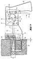
- the device for laying sealing tapes 11 shown in FIGS. 1 and 2 consists essentially of a housing 1, a handle 2, an actuation switch 3, an electrical connection 4, an electric drive motor 5, a reduction gear 6, a stop 9 with stop surface 9a , an insertion device 10, an insertion device 8 and a pressing device 7.
- the pressing device 7 protrudes into the joint 19 of a component 17, 18, is supported with a pressing surface 12 on a side wall 19a of the joint 19 and presses over the further pressing surface 13 the sealing tape 11 introduced in compressed form.
- the sealing tape 11 is adhesively connected to the side wall 19b of the joint 19 by means of an adhesive layer 16.
- the pressing surface 13 is formed by the jacket of an eccentric part of an eccentric 14 which is rotatably arranged relative to the pressing surface 12.
- the eccentric 14 is connected to a reduction gear 6, which is driven is by the motor 5. With the aid of the actuating switch 3, which regulates the current flow to the motor 5, the motor 5 can be set in motion.
- the eccentric 14 is rotated, the outer distance A of the two contact surfaces 12, 13 changes alternately.
- the device has a circular stop 9 with a stop surface 9a. On the stop surface 9a or in a recess of the stop 9, the contact surface 12 is axially displaceable. The contact surface 12 is fixed on the stop 9 by means of a screw 15.
- the insertion device 10 consists essentially of an inlet slope, with the aid of which the sealing tape 11 to be introduced into the joint 19 is deflected into the joint 19. With the aid of the insertion device 8, the sealing tape 11 is pressed into the joint 19 to a corresponding, predetermined depth T and then pressed onto the side wall 19b of the joint 19 with the pressing device 7.
- the eccentric 14 is rotated with the aid of the electric drive motor 5 and the reduction gear 6 in the circumferential direction U, the device moves within the joint 19. After the sealing tape 11 has been inserted or pressed into the joint 19, the device is pulled out of the joint 19, so that the compression of the sealing tape 11 can be released and, with support on both side walls 19a, 19b of the joint 19, closes it tightly.
- the device for laying sealing tapes 39 shown in Fig. 3 consists essentially of a housing 21, a handle 22, an actuating device 23 in the form of a transmission gear 24, a stop 26 with stop surface 26a, an insertion device, not shown, an insertion device 31 and one Pressing device 29.
- the pressing device 29 projects into the joint 41 of a component 27, 28, is supported with a contact surface 37 on a side wall 41a of the joint 41 and presses over the further contact surface 38 onto the sealing band 39 introduced in compressed form.
- the sealing band 39 is in adhesive connection with the side wall 41b of the joint 41 by means of an adhesive layer 40.
- the pressing surfaces 37, 38 cooperate with a pulling wedge 32 which has inclined outer surfaces.
- the inner contour 37b, 38b of the pressing surfaces 37, 38 is designed to be complementary to these inclined outer surfaces.
- the pull wedge 32 is connected to an actuating rod 33, which is guided axially displaceably in a bearing 25 of the housing 21.
- the transmission gear 24, which can be actuated by the actuating lever 23, essentially consists of a rotatable eccentric arranged in the housing 21 34, from which two eccentrically arranged bearing elements 35 protrude at right angles. These bearing elements 35 are encompassed by two transmission levers 23b, 33b, which are connected to the actuating rod 33 and to the actuating lever 23 via joints 23a, 33a.
- the actuating lever 23 is pivotable about a bearing pin 36 of the housing 21.
- the device has a circular stop 26 with a stop surface 26a, on which or in two recesses of the stop 26 the pressing surfaces 37, 38 are arranged so as to be axially displaceable.
- the pressing surfaces 37, 38 are fixed at the stop 26 by means of screws 30.
- the insertion device essentially consists of an inlet slope with which the sealing tape 39 to be introduced into the joint 41 is deflected into the joint 41.
- the insertion device 31 With the aid of the insertion device 31, the sealing tape 39 is pressed into the joint 41 to a corresponding, predetermined depth and then pressed against the side wall 41b of the joint 41 with the pressing device 29. After pressing the sealing tape 39 in the joint 41, the device is pulled out of the joint 41, so that the compression of the sealing tape 39 can be released and, with support on both side walls 41a, 41b, the joint 41 closes tightly.
Abstract
Description
- Die Erfindung betrifft eine Vorrichtung zum Verlegen von Dichtungsbändern in Fugen von Bauteilen mit einer das Dichtungsband in die Fuge lenkenden Einführeinrichtung und einer Einlegeeinrichtung, die das Dichtungsband in der Fuge ausrichtet, sowie einem Anschlag mit Anschlagfläche für die Abstützung der Vorrichtung an der Bauteiloberfläche und einer wenigstens teilweise in die Fuge ragenden Andrückeinrichtung zur Festlegung des Dichtungsbandes in der Fuge.
- Im Massivbau, der Beton, Fertigteile, Mauerwerk inklusive Leichtbeton sowie den Vollwärmeschutz umfasst, dem konstruktiven Holz- und Metallbau sowie im Bereich der Fensterabdichtung zwischen Fensterelement und Bauteil gibt es Fugen, die mit Hilfe von Fugenbändern abgedichtet werden.
- Zur Verarbeitung gelangen Fugenbänder, die in komprimiertem Zustand zu Rollen gewickelt sind und in diesem Zustand in die Fuge verlegt werden.
- Nach dem Einlegen löst sich die Komprimierung und das Fugenband geht in der Fuge auf, dichtet sicher, dauerhaft und gleicht Unebenheiten in der Fuge aus. Nachdem sich die Komprimierung gelöst hat, entwickelt das Fugenband eine Kraft, die fest gegen die sich gegenüberliegenden Seitenwandungen der Fuge drückt.
- Im Handel erhältliche, vorkomprimierte Dichtungsbänder besitzen eine Klebeschicht, die mit einer der sich gegenüberliegenden Seitenwandungen der Fuge in Verbindung bringbar sind. Die Klebeschicht hat den Vorteil, dass Dichtungsbänder in vertikal bzw. über Kopf angeordneten Fugen nicht aus diesen herausfallen können, bevor sich die Komprimierung aufgelöst hat.
- Um eine gute Adhäsion zwischen der Klebeschicht und der entsprechenden Seitenwandung der Fuge zu gewährleisten, werden zum Andrücken des Dichtungsbandes gegen die Seitenwandung der Fuge Hilfsmittel wie Schraubenzieher oder Spachtel verwendet.
- Aus dem DE-GM 87 07 753 ist eine Vorrichtung zum Verlegen von Dichtungsbändern in Form von Schaumstoffprofilen bekannt. Die Vorrichtung weist einen Rahmen, eine Einführeinrichtung, eine Einlegeeinrichtung und eine Andrückeinrichtung auf. Diese bekannte Vorrichtung wird für Dichtungsbänder verwendet, die insbesondere in Fugen mit grösseren Abmessungen eingesetzt werden und ein Eindringen von Wasser verhindern sollen. Beim Einlegen des Dichtungsbandes in die Fuge wird das Dichtungsband um etwa 25 % seiner entspannten Breite zusammengedrückt und in die Fuge eingelegt. Nach dem Abheben der Vorrichtung entspannt sich das Dichtungsband und drückt gegen die sich gegenüberliegenden Seitenwandungen der Fuge. Mit der Andrückvorrichtung wird das in die Fuge eingelegte Dichtungsband auf eine entsprechende, gewünschte Tiefe hineingedrückt.
- Die aus dem DE-GM 87 07 753 bekannte Vorrichtung eignet sich nicht zum Verlegen von vorkomprimierten Dichtungsbändern, da die Andrückvorrichtung lediglich einen Anpressdruck parallel zu den Seitenwandungen der Fuge auf das Dichtungsband ausübt. Eine Anpresskraft rechtwinklig zu einer der beiden Seitenwandungen der Fuge ist mit diesem bekannten Verlegegerät nicht möglich.
- Der Erfindung liegt die Aufgabe zugrunde, eine Vorrichtung zum Verlegen von Dichtungsbändern zu schaffen, mit der das Einführen und das Einlegen sowie das Andrücken der Dichtungsbänder rechtwinklig zu einer der beiden Seitenwandungen der Fuge möglich ist.
- Erfindungsgemäss wird dies dadurch erreicht, dass die Andrückvorrichtung wenigstens zwei Anpressflächen aufweist, wobei der Abstand zwischen den Anpressflächen veränderbar ist.
- Die beiden Anpressflächen verlaufen im wesentlichen parallel zueinander und sind relativ zueinander versetzbar, so dass sich ihr Abstand zueinander verändern lässt. Eine derartig ausgebildete Andrückvorrichtung ist von derartiger Gestalt, dass die beiden Anpressflächen in ihrer Ausgangsstellung zwischen dem in der Fuge eingelegten Dichtungsband und einer der beiden Seitenwandungen der Fuge hineingeführt werden kann.
- Durch ein anschliessendes Betätigen der Anpressflächen werden diese auseinanderbewegt, so dass sich die eine Anpressfläche an einer Seitenwandung der Fuge und die andere Anpressfläche an jener Seite des Dichtungsbandes abstützt, die der Klebeschicht gegenüberliegt.
- Nach dem Anpressen werden die beiden Anpressflächen wieder in die Ausgangsstellung gebracht, um die Andrückvorrichtung in der Fuge in Längsrichtung versetzen zu können, so dass an einer anderen Stelle ein weiterer Anpressvorgang stattfinden kann.
- Um die Vorrichtung zum Verlegen von Dichtungsbändern anwenderfreundlich zu gestalten, steht wenigstens eine Anpressfläche mit einem Antrieb in Verbindung, der die Anpressfläche relativ zur anderen Anpressfläche bewegt. Mit Hilfe eines Antriebes kann die gleichförmige Bewegung der Anpressflächen relativ zueinander und ein gleichmässiges Andrücken des Dichtungsbandes erreicht werden.
- Der Antrieb kann in vorteilhafter Weise mit einer manuell betätigbaren Betätigungseinrichtung in Verbindung stehen, die beispielsweise eine Vorschubeinrichtung ist, die über einen Handgriff mit einem Betätigungshebel betätigbar ist. Beim Ziehen des Betätigungshebels wird eine Betätigungsstange über einen Vorschubmechanismus axial nach vorne bewegt und nach dem Loslassen des Betätigungshebels wieder in ihre Ausgangsstellung zurückbewegt. Die Betätigungsstange steht dabei in Verbindung mit der Andrückvorrichtung.
- Die Bedienungsfreundlichkeit einer derartigen Vorrichtung wird dadurch gesteigert, indem der Antrieb zweckmässigerweise mit einem Antriebsmotor in Verbindung steht, der beispielsweise ein Elektromotor ist. Zwischen dem Antrieb und dem Motor kann eine Drehmomentbegrenzungskupplung angeordnet sein, deren Auslöse-Drehmoment einstellbar ist.
- Die Andrückvorrichtung kann derart ausgestaltet sein, dass vorzugsweise wenigstens eine der Anpressflächen von der Mantelfläche eines Teiles eines Exzenters gebildet ist. Der Exzenter ist dabei drehbar angeordnet, so dass der exzentrische Teil des Exzenters gegenüber der weiteren Anpressfläche parallel derart versetzbar ist, dass sich der Abstand zwischen dem exzentrischen Teil und der Anpressfläche verändern lässt. Eine derartige Andrückvorrichtung ist zwischen das Dichtungsband und der Seitenwandung der Fuge dann einsetzbar, wenn der exzentrische Teil des Exzenters gegenüber der weiteren Anpressfläche am nächsten liegt. Der Abstand zwischen dem Dichtungsband und der Seitenwandung der Fuge ist dabei im wesentlichen grösser ausgebildet als der kleinste äussere Abstand zwischen dem Mantel des exzentrischen Teiles und der Anpressfläche. Für den Andrückvorgang wird der Exzenter in Drehbewegung versetzt, so dass sich der exzentrische Teil abwechselnd von der weiteren Anpressfläche wegbewegt und sich dieser wieder nähert. Diese Bewegung des Exzenters bewirkt einerseits ein Andrücken des Dichtungsbandes gegen die Seitenwandung der Fuge, andererseits eine Fortbewegung der Andrückvorrichtung bzw. der Vorrichtung in der Fuge des Bauteiles.
- Die Fortbewegung der Vorrichtung in der Fuge des Bauteiles kann auch mittels einer Transporteinrichtung erfolgen, die in Verbindung mit der Vorrichtung steht. Eine derartige Transporteinrichtung kann beispielsweise derart aufgebaut sein, dass sich die Transportvorrichtung über gleitende oder abrollende Elemente an der Oberfläche des Bauteiles oder in der Fuge abstützt und über angetriebene Elemente, beispielsweise Antriebsräder, die an der Oberfläche des Bauteiles oder in der Fuge angreifen, fortbewegt. Die gleitenden bzw. rollenden Elemente und die angetriebenen Elemente können miteinander den Anschlag der Vorrichtung bilden.
- Die Erfindung wird anhand von Zeichnungen, die ein Ausführungsbeispiel wiedergeben, naher erläutert. Es zeigen:
- Fig. 1
- eine erfindungsgemässe Vorrichtung zum Verlegen von Dichtungsbändern während des Verlegevorganges in Andrückstellung, teilweise geschnitten;
- Fig. 2
- einen Schnitt durch die Vorrichtung gemäss Fig. 1 entlang der Linie II-II;
- Fig. 3
- eine weitere Vorrichtung, in Andrückstellung, teilweise geschnitten.
- Die in Fig. 1 und 2 dargestellte Vorrichtung zum Verlegen von Dichtungsbändern 11 besteht im wesentlichen aus einem Gehäuse 1, einem Handgriff 2, einem Betätigungsschalter 3, einem elektrischen Anschluss 4, einem elektrischen Antriebsmotor 5, einem Untersetzungsgetriebe 6, einem Anschlag 9 mit Anschlagfläche 9a, einer Einführeinrichtung 10, einer Einlegeeinrichtung 8 und einer Andrückvorrichtung 7. Die Andrückvorrichtung 7 ragt in die Fuge 19 eines Bauteiles 17, 18, stützt sich mit einer Anpressfläche 12 an einer Seitenwandung 1 9a der Fuge 19 ab und drückt über die weitere Anpressfläche 13 auf das in komprimierter Form eingebrachte Dichtungsband 11. Das Dichtungsband 11 steht in adhäsiver Verbindung mit der Seitenwandung 19b der Fuge 19 mittels einer Klebeschicht 16. Die Anpressfläche 13 ist gebildet vom Mantel eines exzentrischen Teiles eines Exzenters 14, der gegenüber der Anpressfläche 12 drehbar angeordnet ist. Der Exzenter 14 steht in Verbindung mit einem Untersetzungsgetriebe 6, welches angetrieben wird von dem Motor 5. Mit Hilfe des Betätigungsschalters 3, der den Stromzufluss zum Motor 5 regelt, ist der Motor 5 in Bewegung versetzbar. Beim Drehen des Exzenters 14 ändert sich abwechslungsweise der äussere Abstand A der beiden Anpressflächen 12, 13. Die Vorrichtung besitzt einen kreisrund ausgebildeten Anschlag 9 mit Anschlagfläche 9a. An der Anschlagfläche 9a bzw. in einer Ausnehmung des Anschlages 9 ist die Anpressfläche 12 axial begrenzt versetzbar angeordnet. Die Festlegung der Anpressfläche 12 am Anschlag 9 erfolgt mittels einer Schraube 15.
- Weiters angeordnet am Anschlag 9 ist die aus einem Teil bestehende Einführeinrichtung 10 und Einlegeeinrichtung 8. Diese beiden Einrichtungen sind mittels zweier Schrauben 20 am Anschlag 9 festgelegt. Die Einführeinrichtung 10 besteht im wesentlichen aus einer Einlaufschräge, mit Hilfe welcher das in die Fuge 19 einzubringende Dichtungsband 11 in die Fuge 19 eingelenkt wird. Mit Hilfe der Einlegeeinrichtung 8 wird das Dichtungsband 11 auf eine entsprechende, vorgegebene Tiefe T in die Fuge 19 hineingedrückt und anschliessend mit der Andrückvorrichtung 7 an die Seitenwandung 19b der Fuge 19 angedrückt. Beim Verdrehen des Exzenters 14 mit Hilfe des elektrischen Antriebsmotores 5 und des Untersetzungsgetriebes 6 in Umfangsrichtung U erfolgt eine Fortbewegung der Vorrichtung innerhalb der Fuge 19. Nach dem Einlegen bzw. Andrücken des Dichtungsbandes 11 in der Fuge 19 wird die Vorrichtung aus der Fuge 19 herausgezogen, so dass sich die Komprimierung des Dichtungsbandes 11 lösen kann und unter Abstützung an beiden Seitenwandungen 19a, 19b der Fuge 19, dieselbe dicht abschliesst.
- Die in Fig. 3 dargestellte Vorrichtung zum Verlegen von Dichtungsbändern 39 besteht im wesentlichen aus einem Gehäuse 21, einem Handgriff 22, einer Betätigungseinrichtung 23 in Form eines Uebersetzungsgetriebes 24, einem Anschlag 26 mit Anschlagfläche 26a, einer nicht dargestellten Einführeinrichtung, einer Einlegeeinrichtung 31 und einer Andrückvorrichtung 29. Die Andrückvorrichtung 29 ragt in die Fuge 41 eines Bauteiles 27, 28, stützt sich mit einer Anpressfläche 37 an einer Seitenwandung 41 a der Fuge 41 ab und drückt über die weitere Anpressfläche 38 auf das in komprimierter Form eingebrachte Dichtungsband 39. Das Dichtungsband 39 steht in adhäsiver Verbindung mit der Seitenwandung 41 b der Fuge 41 mittels einer Klebeschicht 40. Die Anpressflächen 37, 38 wirken mit einem Ziehkeil 32 zusammen, der geneigte Aussenflächen aufweist. Komplementär zu diesen geneigten Aussenflächen ist die Innenkontur 37b, 38b der Anpressflächen 37, 38 ausgebildet. Der Ziehkeil 32 steht in Verbindung mit einer Betätigungsstange 33, die axial versetzbar in einer Lagerstelle 25 des Gehäuses 21 geführt ist. Das Uebersetzungsgetriebe 24, welches vom Betätigungshebel 23 betätigbar ist, besteht im wesentlichen aus einem im Gehäuse 21 angeordneten, drehbaren Exzenter 34, von dem rechtwinklig zwei exzentrisch angeordnete Lagerelemente 35 abragen. Diese Lagerelemente 35 werden umgriffen von zwei Uebertragungshebeln 23b, 33b, die über Gelenke 23a, 33a mit der Betätigungsstange 33 bzw. mit dem Betätigungshebel 23 verbunden sind. Der Betätigungshebel 23 ist um einen Lagerbolzen 36 des Gehäuses 21 schwenkbar.
- Beim Durchziehen des Betätigungshebels 23 in Richtung Handgriff 22 erfolgt eine Kraftübertragung über den Uebertragungshebel 23b auf den Exzenter 34, der dadurch gegen den Uhrzeigersinn in Drehbewegung versetzt wird. Gleichzeitig wird dadurch eine axiale Versetzung der Betätigungsstange 33 und des Ziehkeiles 32 in Richtung Handgriff 22 bewirkt, so dass die beiden Anpressflächen 37, 38 axial auseinander in die Anpresstellung versetzt werden. Lässt der Druck auf den Betätigungshebel 23 nach, so bewegen sich die Uebertragungselemente 23b, 33b , die Scheibe 34, die Betätigungsstange 33 und der Ziehkeil 32 durch die Kraft von nicht dargestellten Federelementen wieder in die ursprüngliche Ausgangslage und der äussere Abstand der beiden Anpressflächen 37, 38 reduziert sich wieder entsprechend. Die Federelemente können mit den Anpressflächen 37, 38 und/oder auf den Betätigungshebel 23 sowie der Scheibe 34 zusammenwirken.
- Die Vorrichtung besitzt einen kreisrund ausgebildeten Anschlag 26 mit Anschlagfläche 26a, an der bzw. in zwei Ausnehmungen des Anschlages 26 die Anpressflächen 37, 38 axial begrenzt versetzbar angeordnet sind. Die Festlegung der Anpressflächen 37, 38 am Anschlag 26 erfolgt mittels Schrauben 30.
- Weiters angeordnet am Anschlag 26 ist eine aus einem Teil bestehende, nicht dargestellte Einführeinrichtung und eine zum Teil sichtbare Einlegeeinrichtung 31. Diese beiden Einrichtungen sind mittels ebenfalls nicht sichtbaren Schrauben am Anschlag 26 festgelegt. Die Einführeinrichtung besteht im wesentlichen aus einer Einlaufschräge, mit welcher das in die Fuge 41 einzubringende Dichtungsband 39 in die Fuge 41 eingelenkt wird. Mit Hilfe der Einlegeeinrichtung 31 wird das Dichtungsband 39 auf eine entsprechende, vorgegebene Tiefe in die Fuge 41 hineingedrückt und anschliessend mit der Andrückvorrichtung 29 an die Seitenwandung 41 b der Fuge 41 angedrückt. Nach dem Andrücken des Dichtungsbandes 39 in der Fuge 41 wird die Vorrichtung aus der Fuge 41 herausgezogen, so dass sich die Komprimierung des Dichtungsbandes 39 lösen kann und unter Abstützung an beiden Seitenwandungen 41a, 41b der Fuge 41 dieselbe dicht abschliesst.
Claims (5)
- Vorrichtung zum Verlegen von Dichtungsbändern (11, 39) in Fugen (19, 41) von Bauteilen (17, 18, 27, 28) mit einer das Dichtungsband (11, 39) in die Fuge (19, 41) lenkenden Einführeinrichtung (10) und einer Einlegeeinrichtung (8, 31), die das Dichtungsband (11, 39) in der Fuge (19, 41) ausrichtet, sowie einem Anschlag (9, 26) mit Anschlagfläche (9a, 26a) für die Abstützung der Vorrichtung an der Bauteiloberfläche und einer wenigstens teilweise in die Fuge (19, 41) ragenden Andrückvorrichtung (7, 29) zur Festlegung des Dichtungsbandes (11, 39) in der Fuge (19, 41), dadurch gekennzeichnet, dass die Andrückvorrichtung (7, 29) wenigstens zwei Anpressflächen (12, 13, 37, 38) aufweist, wobei der Abstand (A) zwischen den Anpressflächen (12, 13, 37, 38) veränderbar ist.
- Vorrichtung nach Anspruch 1, dadurch gekennzeichnet, dass wenigstens eine Anpressfläche (13, 37) mit einem Antrieb in Verbindung steht, der die eine Anpressfläche (13, 37) relativ zur anderen Anpressfläche (12, 38) bewegt.
- Vorrichtung nach Anspruch 1 oder 2, dadurch gekennzeichnet, dass der Antrieb eine manuell betätigbare Betätigungseinrichtung ist.
- Vorrichtung nach Anspruch 1 oder 2, dadurch gekennzeichnet, dass der Antrieb ein Antriebsmotor (5) ist.
- Vorrichtung nach einem der Ansprüche 1 bis 4, dadurch gekennzeichnet, dass wenigstens eine der Anpressflächen (13, ) von der Mantelfläche eines Teiles eines Exzenters (14) gebildet ist.
Applications Claiming Priority (2)
| Application Number | Priority Date | Filing Date | Title |
|---|---|---|---|
| DE4318964A DE4318964C2 (de) | 1993-06-08 | 1993-06-08 | Verlegevorrichtung für Dichtungsbänder |
| DE4318964 | 1993-06-08 |
Publications (2)
| Publication Number | Publication Date |
|---|---|
| EP0628679A1 true EP0628679A1 (de) | 1994-12-14 |
| EP0628679B1 EP0628679B1 (de) | 1996-11-20 |
Family
ID=6489862
Family Applications (1)
| Application Number | Title | Priority Date | Filing Date |
|---|---|---|---|
| EP94810326A Expired - Lifetime EP0628679B1 (de) | 1993-06-08 | 1994-06-02 | Verlegevorrichtung für Dichtungsbänder |
Country Status (4)
| Country | Link |
|---|---|
| US (1) | US5499435A (de) |
| EP (1) | EP0628679B1 (de) |
| AT (1) | ATE145442T1 (de) |
| DE (2) | DE4318964C2 (de) |
Families Citing this family (3)
| Publication number | Priority date | Publication date | Assignee | Title |
|---|---|---|---|---|
| DE19616674C2 (de) * | 1996-04-26 | 1998-09-03 | Audi Ag | Verfahren zur Montage eines biegeschlaffen, länglichen Konstruktionselementes und Werkzeug zur Durchführung des Verfahrens |
| DE10119440B4 (de) * | 2001-04-20 | 2005-12-08 | Rohde & Schwarz Gmbh & Co. Kg | Verlegevorrichtung für eine Dichtschnur |
| DE102014113509A1 (de) * | 2014-09-18 | 2016-03-24 | Aytec Automation Gmbh | Vorrichtung zum Applizieren eines Gummiprofils |
Citations (5)
| Publication number | Priority date | Publication date | Assignee | Title |
|---|---|---|---|---|
| US3246390A (en) * | 1963-04-10 | 1966-04-19 | Brown Co D S | Tool for compressing and inserting compressible strips in slots |
| US3363303A (en) * | 1965-08-26 | 1968-01-16 | P O Box 18992 | Weatherstrip mounting hand tool |
| DE8707753U1 (de) * | 1987-05-30 | 1987-07-16 | Possehl Spezialbau Gmbh, 6200 Wiesbaden, De | |
| DE8618558U1 (de) * | 1986-07-11 | 1987-10-08 | Phoenix Ag, 2100 Hamburg, De | |
| DE4104342C1 (en) * | 1991-02-13 | 1992-09-17 | Bruegmann Frisoplast Gmbh, 2990 Papenburg, De | Hand tool for sealing profile assembly - has sealing profile stamping cutter with V=shaped blade in guide duct |
Family Cites Families (8)
| Publication number | Priority date | Publication date | Assignee | Title |
|---|---|---|---|---|
| US3052973A (en) * | 1959-03-02 | 1962-09-11 | Samuel E Williams | Tool for removing bushings |
| US3021112A (en) * | 1959-11-09 | 1962-02-13 | Michael L Forman | Wedging tool |
| US3307249A (en) * | 1965-03-26 | 1967-03-07 | Teletype Corp | Gasket inserting tool |
| US3705581A (en) * | 1970-12-17 | 1972-12-12 | Leon A Drake | Cast spreading device |
| US4443001A (en) * | 1982-05-19 | 1984-04-17 | Haerer James P | Hydraulically operated hand tool for forcing open doors |
| US4433463A (en) * | 1982-09-13 | 1984-02-28 | William Diedrich | Multipurpose prying tool |
| DE8808530U1 (de) * | 1988-07-04 | 1988-09-15 | Possehl Spezialbau Gmbh, 6200 Wiesbaden, De | |
| US5127143A (en) * | 1990-04-02 | 1992-07-07 | North Country Thermal Line, Inc. | Apparatus for seating an elongated flexible spline in a window frame to secure a flexible screen thereto |
-
1993
- 1993-06-08 DE DE4318964A patent/DE4318964C2/de not_active Expired - Fee Related
-
1994
- 1994-06-02 AT AT94810326T patent/ATE145442T1/de not_active IP Right Cessation
- 1994-06-02 DE DE59401062T patent/DE59401062D1/de not_active Expired - Fee Related
- 1994-06-02 EP EP94810326A patent/EP0628679B1/de not_active Expired - Lifetime
- 1994-06-08 US US08/255,691 patent/US5499435A/en not_active Expired - Fee Related
Patent Citations (5)
| Publication number | Priority date | Publication date | Assignee | Title |
|---|---|---|---|---|
| US3246390A (en) * | 1963-04-10 | 1966-04-19 | Brown Co D S | Tool for compressing and inserting compressible strips in slots |
| US3363303A (en) * | 1965-08-26 | 1968-01-16 | P O Box 18992 | Weatherstrip mounting hand tool |
| DE8618558U1 (de) * | 1986-07-11 | 1987-10-08 | Phoenix Ag, 2100 Hamburg, De | |
| DE8707753U1 (de) * | 1987-05-30 | 1987-07-16 | Possehl Spezialbau Gmbh, 6200 Wiesbaden, De | |
| DE4104342C1 (en) * | 1991-02-13 | 1992-09-17 | Bruegmann Frisoplast Gmbh, 2990 Papenburg, De | Hand tool for sealing profile assembly - has sealing profile stamping cutter with V=shaped blade in guide duct |
Also Published As
| Publication number | Publication date |
|---|---|
| EP0628679B1 (de) | 1996-11-20 |
| DE4318964C2 (de) | 2002-08-29 |
| DE4318964A1 (de) | 1994-12-15 |
| US5499435A (en) | 1996-03-19 |
| ATE145442T1 (de) | 1996-12-15 |
| DE59401062D1 (de) | 1997-01-02 |
Similar Documents
| Publication | Publication Date | Title |
|---|---|---|
| DE2825023C2 (de) | ||
| AT504375B1 (de) | Möbel mit einer antriebsvorrichtung für bewegbare möbelteile | |
| EP0121165A1 (de) | Lenkradschloss | |
| EP0273907B1 (de) | Verfahren und vorrichtung zum setzen von blindnieten | |
| DE3003703A1 (de) | Schluessellose spannfutterkonstruktion | |
| EP0628679B1 (de) | Verlegevorrichtung für Dichtungsbänder | |
| EP1101990A1 (de) | Verfahren und Vorrichtung zur Spaltabdichtung | |
| DE2913281C2 (de) | Stoßverbindung eines Kämpferprofils mit einem Rahmen- oder Sprossenprofil für Fenster, Türen o.dgl. | |
| DE3320193C2 (de) | Türbeschlag | |
| DE2443376C2 (de) | Pneumatisch oder hydraulisch betätigbare Rahmenpresse | |
| DE3303631A1 (de) | Verfahren und vorrichtung zum biegen von hohlen metallprofilen, insbesondere rahmenprofilen fuer fenster und tueren | |
| EP1789639A2 (de) | Verspannbares bauelement für einen kühlraum | |
| DE3941935C2 (de) | Spannschloß | |
| DE2510884B2 (de) | Vorrichtung zum verbinden von zwei auf gehrung geschnittenen metallprofilstaeben | |
| EP0318720A2 (de) | Vorrichtung zur automatischen Längenverstellung eines Bowdenzuges | |
| EP1183702B1 (de) | Knebelverbindung | |
| DE2824301A1 (de) | Verbindungseinheit fuer rolladenaufbauelemente | |
| EP2679759B1 (de) | Eckverbinder für Hohlprofilrahmen | |
| DE19730123A1 (de) | Werkzeug zum Anbringen eines Dicht- und Abdeckstreifens auf einen Flansch | |
| DD226147A3 (de) | Einrichtung zur verriegelung des stoessels an pressen | |
| DE2809584A1 (de) | Vorrichtung zum verbinden von rahmenteilen | |
| EP0997211B1 (de) | Verfahren und Vorrichtung zur Herstellung der Eckverbindung von Verkleidungselementen | |
| EP2083491A2 (de) | Leitungskanal für elektrische Leitungen | |
| EP0102448B1 (de) | Vorrichtung zum Einbringen eines Dichtungsstranges aus elastischem Material in eine Bauwerksfuge | |
| EP2072198B1 (de) | Gehäuseeinheit mit einer Rasteinheit für Trennscheibengeräte und dergleichen |
Legal Events
| Date | Code | Title | Description |
|---|---|---|---|
| PUAI | Public reference made under article 153(3) epc to a published international application that has entered the european phase |
Free format text: ORIGINAL CODE: 0009012 |
|
| AK | Designated contracting states |
Kind code of ref document: A1 Designated state(s): AT CH DE FR GB LI |
|
| 17P | Request for examination filed |
Effective date: 19941228 |
|
| GRAG | Despatch of communication of intention to grant |
Free format text: ORIGINAL CODE: EPIDOS AGRA |
|
| GRAH | Despatch of communication of intention to grant a patent |
Free format text: ORIGINAL CODE: EPIDOS IGRA |
|
| 17Q | First examination report despatched |
Effective date: 19960403 |
|
| GRAH | Despatch of communication of intention to grant a patent |
Free format text: ORIGINAL CODE: EPIDOS IGRA |
|
| GRAA | (expected) grant |
Free format text: ORIGINAL CODE: 0009210 |
|
| AK | Designated contracting states |
Kind code of ref document: B1 Designated state(s): AT CH DE FR GB LI |
|
| REF | Corresponds to: |
Ref document number: 145442 Country of ref document: AT Date of ref document: 19961215 Kind code of ref document: T |
|
| REF | Corresponds to: |
Ref document number: 59401062 Country of ref document: DE Date of ref document: 19970102 |
|
| ET | Fr: translation filed | ||
| GBT | Gb: translation of ep patent filed (gb section 77(6)(a)/1977) |
Effective date: 19970128 |
|
| PLBE | No opposition filed within time limit |
Free format text: ORIGINAL CODE: 0009261 |
|
| STAA | Information on the status of an ep patent application or granted ep patent |
Free format text: STATUS: NO OPPOSITION FILED WITHIN TIME LIMIT |
|
| 26N | No opposition filed | ||
| PGFP | Annual fee paid to national office [announced via postgrant information from national office to epo] |
Ref country code: CH Payment date: 20010529 Year of fee payment: 8 |
|
| PGFP | Annual fee paid to national office [announced via postgrant information from national office to epo] |
Ref country code: FR Payment date: 20010611 Year of fee payment: 8 |
|
| PGFP | Annual fee paid to national office [announced via postgrant information from national office to epo] |
Ref country code: AT Payment date: 20010613 Year of fee payment: 8 |
|
| REG | Reference to a national code |
Ref country code: GB Ref legal event code: IF02 |
|
| PGFP | Annual fee paid to national office [announced via postgrant information from national office to epo] |
Ref country code: GB Payment date: 20020529 Year of fee payment: 9 |
|
| PG25 | Lapsed in a contracting state [announced via postgrant information from national office to epo] |
Ref country code: AT Free format text: LAPSE BECAUSE OF NON-PAYMENT OF DUE FEES Effective date: 20020602 |
|
| PGFP | Annual fee paid to national office [announced via postgrant information from national office to epo] |
Ref country code: DE Payment date: 20020610 Year of fee payment: 9 |
|
| PG25 | Lapsed in a contracting state [announced via postgrant information from national office to epo] |
Ref country code: LI Free format text: LAPSE BECAUSE OF NON-PAYMENT OF DUE FEES Effective date: 20020630 Ref country code: CH Free format text: LAPSE BECAUSE OF NON-PAYMENT OF DUE FEES Effective date: 20020630 |
|
| REG | Reference to a national code |
Ref country code: CH Ref legal event code: PL |
|
| PG25 | Lapsed in a contracting state [announced via postgrant information from national office to epo] |
Ref country code: FR Free format text: LAPSE BECAUSE OF NON-PAYMENT OF DUE FEES Effective date: 20030228 |
|
| REG | Reference to a national code |
Ref country code: FR Ref legal event code: ST |
|
| PG25 | Lapsed in a contracting state [announced via postgrant information from national office to epo] |
Ref country code: GB Free format text: LAPSE BECAUSE OF NON-PAYMENT OF DUE FEES Effective date: 20030602 |
|
| PG25 | Lapsed in a contracting state [announced via postgrant information from national office to epo] |
Ref country code: DE Free format text: LAPSE BECAUSE OF NON-PAYMENT OF DUE FEES Effective date: 20040101 |
|
| GBPC | Gb: european patent ceased through non-payment of renewal fee |
Effective date: 20030602 |